Advertisement
Quick Links
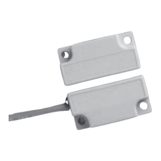
Description
The 341-BT Series 300 DPST safety interlock switch is designed for use with safety
monitored relays or monitored circuits. To achieve the optimum Series 300 defeat
resistant feature of the 341-BT, both the switch circuit (Circuit 1) and the tamper
circuit (Circuit 2) must be connected. An optional third circuit can be provided to
indicate at the panel which guard is open.
Notes:
1. Environmental: Pollution Degree II
2. Correct use of this control device is an essential part of proper machine cycle
control.
3. Failure to follow ALL instructions could lead to serious bodily injury or death.
4. Maintenance to be done by qualified personnel only
5. The connecting cables between the INT devices and the switches must be located in
an IP 23 type enclosure (minimum).
6. The mounting for the switch and the actuator magnet must be accomplished per
this specification.
7. Non-removable hardware must be used for installation.
8. The housing of the 300-BT Series GuardSwitches must be connected to the PE
(Primary Earth) ground circuit via a lock washer on the mounting screw. The PE
ground symbol must be placed adjacent to the screw.
To verify switch operation with an ohmmeter:
Set range at 20 mega ohms (switches with triac output, set ohm range at 20 kilo
ohms). For a normally open switch, the meter will read a high impedance with the
actuator away. It will read very high to infinity range (triac switches will read high kilo
ohm to infinity range) with the actuator within sense range. You will see the opposite
reading for a normally closed switch.
Dimensions
2.13"
5.41cm
0.19''
1.75"
0.48cm
4.45cm
0.57"
1.45cm
0.86"
2.18cm
1.08"
2.74cm
0.22"
0.11"
0.56cm dia.
0.28cm
GuardSwitch
Safety Interlock Switch
341-BT
341-BT-06(J)(K)
341-BT-12(J)(K)
341-BT-20K
343-BT
341-BT-25J
341-B3T-06J
341-B3T-12J
341-B3T-20J
341-B3T-25J
Installation
Use non-removable screws, bolts, or nuts to mount the switch and actuator. Do not
over-torque mounting hardware.
1. Position the switch and actuator so the labels are reading in the same direction
(See Figure 1.)
2. Mount the switch on the stationary frame of the machine and mount the actuator
on the moveable guard, door or gate. Keep the switch and actuator within the
listed sense range. (See Ordering Information.)
See Figure 2 for recommended mounting configurations.
3. Mounting on a ferrous material will effect the sense range a minimum of 50%.
However, a 1/4" non-ferrous spacer positioned under the actuator and/or switch
should restore most of the lost sense range.
4. For best protection against operator defeat, mount with non-removable screws,
bolts or nuts (see Accessories).
5. Caution! When not used with a GE INT safety relay, particular care must be taken to
determine the actual load of the switch circuit. High voltage transients from coils,
motors, contactors, and solenoids must be considered. Transient protection, such
as back-to-back zener diodes (TransZorb
such loads to ensure that maximum ratings of the switch are not exceeded. Not
recommended to be used with tungsten filament loads because of high current
inrush surges. Line capacitance and load capacitance must be considered.
Excessive line capacitance can be caused by cable lengths over 50' when using a
maximum 48 VAC.
™
Series 300
341-B3T-30J
341-BLT-06(J)(K)
341-BLT-12(J)(K)
341-B3LT-06J
341-B3LT-12J
341-B________
343-B________
®
) or an RC network, is recommended for
continued
Advertisement

Related Manuals for GE GuardSwitch 341-BT Series


Summary of Contents for GE GuardSwitch 341-BT Series
- Page 1 4. For best protection against operator defeat, mount with non-removable screws, bolts or nuts (see Accessories). 0.86" 2.18cm 5. Caution! When not used with a GE INT safety relay, particular care must be taken to 1.08" determine the actual load of the switch circuit. High voltage transients from coils, 2.74cm motors, contactors, and solenoids must be considered.
-
Page 2: Mounting Configurations
30 VDC be used is 50, although troubleshooting and line resistance must be considered. (Do not exceed 30 Ohms of combined contact and line resistance. Each GuardSwitch will have less than 0.5 Ohms of resistance.) GE Security Industrial GuardSwitch Series 300... -
Page 3: General Specifications
Note – The LED on the BLT model Fuses: 4A (250V, will be ON when the guard is open 5x20 mm F Fuses: 1A (250V) 230 VAC 120 VAC LOADS 60 VDC 30 VDC GE Security Industrial GuardSwitch Series 300... -
Page 4: Electrical Specifications
Proximity of ferrous materials usually reduces sense range — typically by 50%. The shape and type of material cause a wide diversity of effects. Testing is required to determine actual sense range for specific applications. GE Security Industrial ©2004 GE Security Industrial. GE Security Industrial reserves the right to change specifications without notice. SI-3901-0204 14107 Rev C...
Need help?
Do you have a question about the GuardSwitch 341-BT Series and is the answer not in the manual?
Questions and answers