Table of Contents
Advertisement
Quick Links
Advertisement
Table of Contents

Subscribe to Our Youtube Channel
Related Manuals for TransTel Communications Lynx DK Series


Summary of Contents for TransTel Communications Lynx DK Series
- Page 1 Telephone System Master Programming Manual Rev 2.1c...
- Page 3 Notification Notification is hereby given that TransTel Communications, Inc. reserves the right to modify, change, update or revise this document from time to time as required without the prior obligation to notify any person, company or organization. Further, TransTel Communications, Inc. makes no warranty or representation, either express or implied, with respect to merchantability, or fitness of its products for a particular purpose.
-
Page 4: Table Of Contents
Table of Contents General Description - Introduction..........................15 FCC Rules and Regulation ............................15 FCC Registration Number ............................15 Ringer Equivalence Number 0.3B..........................15 Notification of the Telephone Company........................15 Direct Connection to a Party-Line or Coin Operated Telephone Line is Prohibited...........15 Incidence of Harm to the Telephone Lines........................15 Compatibility of the Telephone Network and Terminal Equipment................16 Radio Frequency Interference ...........................16 CTR 21 (98/482/EC) Declaration Network Compatibility..................16... - Page 5 G1K-NFC 128 ................................29 Install G1K-TLU 2 CO line 4 port SLT........................30 Installing the Equipment ............................31 Backboard ................................. 31 Key Service Unit................................ 31 Power Supply ................................31 Check Your power adapter............................ 31 Mount Power adapter ..............................31 Preparing The External Battery Backup........................31 Charging the Battery ..............................
- Page 6 01. Hold Recall Time ..............................48 02. Exclusive Hold Recall Time ..........................48 03. Hold Recall Timeout ............................48 04. DISA & ECF Access Delay Time - Day .......................49 05. Busy Remind Cycle Time (Off-Hook Ringing) .....................49 06. Pause Time................................49 07. DTMF Generation Time............................49 08.
- Page 7 07. Hold Feature for SLT............................61 08. Station Hunting Group - Ring Method: ........................ 62 Program 05-07-IP : System Timing Parameters – 07....................63 01. Intercom Searching ............................. 63 02. Toll Override Prevention from Quick Dial......................63 03. Paging Alert Tone..............................63 04.
- Page 8 01. Intercom Hot Key Dialling ............................79 02. Immediate SMDR Output ............................79 03 Caller ID Buffer Block Size ...........................80 04. Reserved ................................80 05. CLI Record Storing Method for LCD Phones.......................80 06. CTI-Trunk Status Report .............................80 07. Least Cost Routing – Weekly Holiday 1 ......................80 08.
- Page 9 05. Reserved ................................90 06. Reserved ................................90 07. Reserved ................................90 08. Reserved ................................90 Program 05-20-IP : System Timing Parameters – 20....................91 01. VMU Mailbox Delete All Messages ........................91 02. DISA No Digits Dialed (End of Message) Destination..................91 03.
- Page 10 07. Reserved ................................107 08. Polarity Reversal..............................107 Program 17-nn : Forced Account Code .........................110 Program 18-nn-TK : Assign Toll Plan To Trunk Lines..................111 Program 20-nn- : Set Day – Time / Lunch Time Schedule..................112 Program 25 : Reset Data to System Default ......................113 Program 29-tk-IP : Trunk Specifications –...
- Page 11 05. Toll plan - Day ..............................128 06. Toll plan - Night ..............................128 07. Port Number..............................128 Program 42-stn-IP : Register Memory Blocks for Individual Speed Dial ............129 Program 43-cn-IP : Port Specifications ......................... 130 01. Station Number ..............................130 02.
- Page 12 08. Reserved ................................141 Program 50-stn-IP : Station Class of Service – 6 ....................142 01. ACP Warning Signals ............................142 02. Call Forward Indication: .............................142 03. Reserved: ................................142 04. CTI-Extension Status Report ..........................142 05. VMS Leading Digits For Intercom Calls......................143 06. ACP Door Unlock Relay ............................143 07.
- Page 13 Program 92-CN : ACP TIME LOCK – Assign Card ....................166 Program 93 : MINI CALL ACCOUNTING AOC ADDITIONAL NUMBER CHARGING........... 167 Program 94-tk-IP : Lunchtime Ringing And Ringing Line Preference Assignment .......... 169 Program 95-tk-IP : Trunk Specifications – 3 ......................170 01.
- Page 14 Intercom Dialling restrictions ..........................176 System Clock................................176 Date and Time Setup ............................176 System Alarm...............................176 Wake Up calls ..............................176 Station Numbering ..............................176 Single Line Telephone .............................177 Miscellaneous ................................177 Monitor .................................177 Paging ..................................177 Call Forward No Answer Transfer Time.......................177 Hot Line................................177 Optional Services..............................177 Door phone &...
-
Page 15: General Description - Introduction
General Description - Introduction ® The General Description section contains an easy to understand overview of the TransTel Lynx Hybrid Telephone System. It is the intent of this document to provide both technical and non-technical readers with information pertaining to the system building blocks, capabilities, key highlights, electrical, physical and environmental characteristics of the TransTel Lynx Hybrid Telephone System. -
Page 16: Compatibility Of The Telephone Network And Terminal Equipment
Compatibility of the Telephone Network and Terminal Equipment. Availability of telephone interface information. Technical information concerning interface parameters and specifications not specified in FCC Rules, including the number of Ringers which may be connected to a particular line, which is needed to permit Terminal Equipment to operate in a manner compatible with Telephone Company communications facilities, shall be provided by the Telephone Company upon customer's request. -
Page 17: Economy And Efficiency
Productive TransTel Digital Key Telephones offer thoughtfully designed productive feature access to keep you connected with one another and customers. TransTel Communications, Inc. technology leads the industry in providing for compatibility with devices such as fax machines, answering machines, cordless phones, computer modems and other office/home equipment. -
Page 18: Varied Extension Alternatives
Varied Extension Alternatives You can connect proprietary TransTel DK series Keyphone, Door Phones and conventional industry standard single line sets – Modem, Answering Machine, Cordless phone, etc. directly to the KSU. This feature provides you with the choice to select different extension equipment to suit individual applications. Page 18... -
Page 19: Liquid Crystal Display
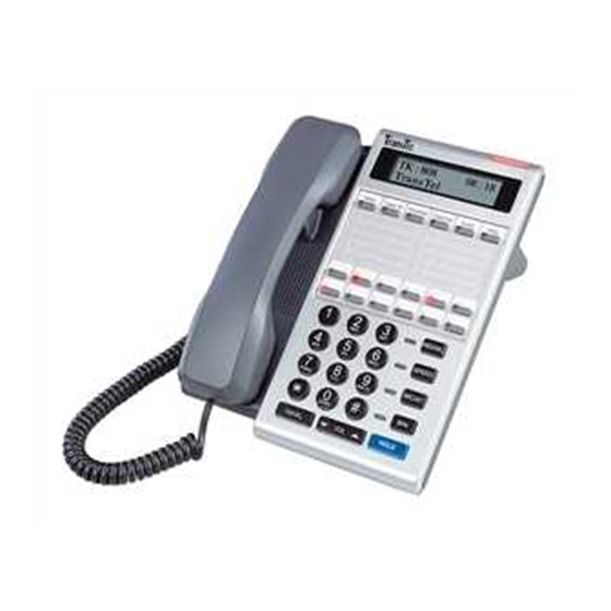
Liquid Crystal Display The DK Series Telephone Model DK6 and DK7 phones are equipped with a large, easy to read LCD display. The LCD is 32 characters total, comprised of 2 rows by 16 characters each. This LCD provides an invaluable tool for simplifying the use of the telephone by identifying the calling extension by name, outside lines by name and self prompting displays for feature access. -
Page 20: Mechanical Specifications (Key Service Unit)
Specifications MAXIMUM LOOP RESISTANCE/IMPEDANCE Key Telephone Less than 40 ohms 26 AWG / 200 m Single Line telephone Less than 800 ohms 26 AWG / 800 m DoorPhone Less than 40 ohms INTERNAL RELAY CONTACTS Type SPST Rating 1 AMP, 24VDC Function Door Switch, Music on Hold, etc CABLE REQUIREMENTS... -
Page 21: Features
Features System Features Account Code Capability Host PABX Access Attendant Console Assignment Hot line Attendant Overflow Line Group Assignment Automatic Line Access Loud Bell Assignment Automatic Line Search Multiple Attendant Consoles Automatic Ringdown Multiple Trunk Groups Automatic Wake-up Night Transfer Battery Charger On Call Programming Behind PABX Operation... -
Page 22: Station Features
Chain Dialling Conference Station Features Dial By Name (LCD Phones) Dial Access to Attendant Advisory Messages Direct Station Selection Access to System Programming DoorPhone Access Account Code Capability Do Not Disturb (DND) Auto Hold Dual Color LED Auto Hold Recall Duration Time Display (LCD Phones) Automatic Call Back Executive Override (Barge-In) -
Page 23: Parts & Peripherals
Parts & Peripherals System Modules Model Description G1-KT-308P KSU with 3 CO lines, 4 Digital ports and 4 Slt ports with CLIP (Caller ID) function RS232/Relay/Sensor G1K-TLU Trunk/Single Line Card : 2 CO lines and 4 SLT ports / with CLIP (Caller ID) function Type of Phones Model Description... - Page 24 Page 24...
-
Page 25: System Installation - Introduction
System Installation - Introduction This section provides directions for installing the system and optional equipment. The installation must be performed by qualified service personnel. Main components of the system are: Key Service Unit, which includes: Optional Expansion Cards: Power Supply Unit (G1K-PWU) TLU Card (2 CO + 4 single line port circuits) •... -
Page 26: Site Requirements
TransTel Communications, Inc. or Authorized Dealers. Damaged Boxes - If you notice any damage to the packages, please notify both the shipper and • TransTel communications, Inc. or Authorized Dealers at once. List of parts included in basic KSU box: •... -
Page 27: Installing Expansion And Optional Cards
3. STATIC SENSITIVE DEVICES! Please handle with care. Installing expansion and optional cards In this step you will be installing printed circuit cards on to header pins of the main board in the basic cabinet. Take your time and extra care to assure the printed circuit cards are properly aligned. After installing each option and expansion card, perform a visual inspection to assure the printed circuit card is installed properly. -
Page 28: G1K-Mbu2 Main Board Unit
G1K-MBU2 Main Board Unit 1. CN1: Power connection to G1K-PWU CN3 2. LED2: DSP operation indication when slow flashing is normal 3. CN11: To G1K-NFC 128 CN1 4. EC1: Gold capacitor which provided for Real Time Clock 5. CN2: To G1K-TLU CN1 6. -
Page 29: G1K-Tlu 2 Port Co Line And 4 Port Slt
G1K-TLU 2 Port CO Line and 4 Port SLT CN1: To G1K MBU CN2 CN3: CO 4 and CO 5 input from Central Office CN5: Connections for SLT port 19, 20 (ST9~ST10) CN4: Connections for SLT port 21, 22 (ST11~ST12) G1K-NFC 128 CF Card G1K-NFC (32kbps) -
Page 30: Install G1K-Tlu 2 Co Line 4 Port Slt
Install G1K-TLU 2 CO line 4 port SLT Power off the system before installing card Install 2 spacers to the MBU by removing screws from the MBU and replacing with spacers Align CN1 of the G1K-TLU card with CN2 of the G1K-MBU. Align the hole on right side of G1K-SLU with the standoff. -
Page 31: Installing The Equipment
Installing the Equipment Backboard Be sure to plan and allow enough space to Mounting Tabs mount and connect the key service unit, power supply and system battery back up if applicable. Key Service Unit Key Service Unit Use the enclosed paper template to locate the mounting position for the Key Service Unit. -
Page 32: Charging The Battery
Charging the Battery The rechargeable batteries are automatically charged when the KSU is plugged in. When System is in a full-load condition (seven CO Trunks and 16 Extensions all in use), the batteries provide a minimum of 1 hour's consecutive use. Change the batteries every two years. Installing or Replacing Batteries Caution To Reduce the Risk of Fire or Injury to persons, Read and Follow these Instructions. -
Page 33: Digital Key Telephone -Dk6 - Dk7
connector. Attention to proper cabling will go a long way towards a successful installation and minimizing service calls after installation. Some guidelines for running station cable are as follows: Avoid running cable parallel to fluorescent light fixtures or electrical lines not in conduit. If these obstacles are unavoidable, run the cable at right angles across them. - Page 34 Page...
-
Page 35: Access Control Telephone/Door Phone - Acp/Dpu
Access Control Telephone/Door Phone – ACP/DPU A cable cover is provided with the KSU. Station cables enter from bottom of the KSU. Remove the cover as required and route the station cable through the hole. Terminate the station wires with the connectors that are provided. -
Page 36: Single Line Telephone (Connected To G1K-Mbu)
Single Line Telephone (connected to G1K-MBU) Station cables can enter from the bottom of the KSU. Remove the cover and route the station cable through the hole. Terminate the station wires with the connectors that are provided. The stations will connect to the KSU as shown on the main panel (above) on connector locations ST5~ST8 (port15~port18) or ST9~ST12 (port19~port22) (Needs G1K-TLU installed). -
Page 37: Optional Cabling
Optional Cabling Connect a 6 conductor mounting cord from the KSU to a RJ-25 modular block. Door Switch (Relay) Connection One Door Switch (24+-12VDC) may be used on the G1K-MBU. 2-conductor wiring is required. Connect the door switch to pins 1 and 6 of the RJ-11 connector. Sensor Connection The Sensor connector on G1K-MBU may be used for the External Sensor input. -
Page 38: Rs232 Port Connection
RS232 Port Connection Use the RJ-11 connector to terminate the RS232 cable. Then connect the RJ-11 to the KSU with a 6 conductor line cord. Insert the line cord into the connector labeled RS-232. Notice: Do not exceed the cable length limitation (15M / 50 feet.) for the RS232 connection VMU Setup The G1K-MBU contains a G1K-NFC card 2 Channel Auto Attendant with voice messaging. -
Page 39: Power On And Operational Test
Power On and Operational Test Before connecting the G1K Power Adapter to AC power: Verify that input voltage and Adapter input voltage are correct before you power up the system. Recheck the cabling for incorrect connections, loose wires and wiring fragments that may cause short-circuits. - Page 40 Page...
-
Page 41: Introduction
Introduction The manual contains all the parameters that could be flexible programmed inside the LYNX+ Hybrid IP Telephone System. New Systems We recommend that all new systems have the system memory reset before system programming takes place. This ensures that any extraneous information that may be present in system memory is erased and that the system database will not be corrupt for unpredicted data. -
Page 42: Basic Programming Commands
Basic Programming Commands Enter Programming: To begin database programming in LYNX+ from a LCD display phone, press [PRG], [2], Enter Password if programmed. (New systems will not have a system password). Press [SAVE] key then you will see the LCD display as follow: PROGRAM MODE: __ (01 –... -
Page 43: Alphanumeric Entry
[REDIAL] {CLEAR ALL}: Clears all digits on an entry such as speed dial or account codes. Alphanumeric Entry: The following table indicates the capabilities of the name programming functions if they are selected on the system. System Speed Dial, Personal Speed Dial, Stations, CO Lines and Sensors may be programmed with names. -
Page 44: Dk6 Key Telephone - Key Layout (18 Button)
DK6 Key Telephone – Key Layout (18 Button) DK7 Key Telephone – Key Layout Page... -
Page 45: Lynx System Setup
LYNX System Setup The LYNX system has been setup to enable it to be plugged in and turned on to enable a customer to use the system with little or no Programming changes. The following details some of the points you should be aware of, please refer to your Manual for more detailed information. -
Page 46: Program 01-Tk-Ip : Day Ringing And Ringing Line Preference Assignment
Program 01-tk-IP : Day Ringing And Ringing Line Preference Assignment tk=Trunk No. (01-12), IP=Item Pointer (01-26) 01-tk-IP FLX DAY Assigned station number 11 12 13 14 General: This program assigns each incoming line to ring the programmed stations. The ringing methods can be LINEAR (ring the first available station), CIRCULAR (Ring the next station following the last station who just answered an incoming call), HUNT (Ring the first assigned station for a set period of time (program mode 05-08-01) then if no answer ring the next ring assigned station then the next etc.) or COMMON... -
Page 47: Program 03-01-Ip : Door Phone Ringing Assignment
Program 03-01-IP : Door Phone Ringing Assignment IP = 01-26 03-01-IP Door Assigned station number. 11 12 13 14 15 General: This program assigns the Door Phone/s to ring the programmed stations. Description: 1. To assign an ACP or digital door phone to follow Mode 03 it must be set to “d” in mode 46-st-07. Otherwise it will ring the stations assigned in the Hunt Group allocated in mode 46-st-07 2. -
Page 48: Program 05-01-Ip : System Timing Parameters - 01
Program 05-01-IP : System Timing Parameters – 01 05-01-IP SYS PAR IP=Item Pointer (01-08) Value for each Item 1 1 1 1 4 2 2 1 Value Default Item Description 1= 60 sec. Hold Recall Time 1= 60 sec. Exclusive Hold Recall Time 1= 60 sec. -
Page 49: Disa & Ecf Access Delay Time - Day
04. DISA & ECF Access Delay Time - Day This parameter sets the timer that a DISA/ECF (External Call Forwarding) trunk will ring assigned stations (set by Program 01-tk-IP, 02-tk-IP) prior to be connected to Auto Attendant (DISA) or another Trunk (ECF) in Day mode. -
Page 50: Call Forward No Answer Transfer Time
08. Call Forward No Answer Transfer Time This parameter sets the timer between a call is ringing a station (set Call Forward No Answer) and then be transferred to the station been forwarded. IP \ Value Unit 05-01-08 Page... -
Page 51: Program 05-02-Ip : System Timing Parameters - 02
Program 05-02-IP : System Timing Parameters – 02 IP=Item Pointer (01-08) 05-02-IP SYS PAR Value for each item 5 5 1 2 1 0 2 4 Value Default Item Description 5= 15 Sec. SLT Dial Tone Timeout 5= 15 Sec. SLT Inter-Digit Timeout 1= 10 Sec. -
Page 52: Slt Release Signal Time
04. SLT Release Signal Time The time duration of depressing the hook switch of an SLT longer than this timer and then system will recognize it as a Release Signal. Please note that the system will take it as a Hold signal if less than this timer but longer than the SLT Hold Signal Timer (Program 05-02-06). -
Page 53: Program 05-03-Ip : System Timing Parameters - 03
Program 05-03-IP : System Timing Parameters – 03 IP=Item Pointer (01-08) 05-03-IP SYS PAR Value for each Item 0 0 1 9 0 3 0 6 Value Default Item Description 0= 33/66 Make / Break Ratio 0= Yes Automatic Trunk Search 1= Ringing Intercom Call Signalling Method 1= 1... -
Page 54: Toll Access Code
05. Toll Access Code It is the first dialling digit that will be checked as an effective Toll Call or not. This has no effect on toll control within the system. It is only used to notify SMDR that a call is Toll Call or not. Refer to Program 14-01-03. -
Page 55: Program 05-04-Ip : System Timing Parameters - 04
Program 05-04-IP : System Timing Parameters – 04 IP=Item Pointer (01-08) 05-04-IP SYS PAR Value for each Item 8 1 0 0 0 0 0 0 Value Default Item Description 8 = 115200 System Baud Rate Setting 1= Enable Dial 9 Flag 0= Warning Action for Call Duration Limiting 0= 12 Hours... -
Page 56: 24 Hours Clock
04. 12/24 Hours Clock This parameter to let the time displayed on LCD display of key phone to be formatted as 12 Hours or 24 Hours Clock. IP \ Value 05-04-04 12 Hours Clock 24 Hours Clock 05. SLT Hook Flash Answer Delay This timer provides a guard time to prevent an SLT user from making an un-intended Hook Flash, such as lifting the handset but dropping on hook again, when it tries to answer a call. -
Page 57: Slt Message Waiting Method
08. SLT Message Waiting Method IP \ Value 05-04-08 90V DC Ring Two 250 ms. Ring Burst Description: 0=90V Message light 90Volts DC will operate industry standard neon light message waiting phones. 1=Auto Ring If the setting is Ring, the single line phone will receive 30 seconds intercom ringing every 5 minutes until the station answers. -
Page 58: Program 05-05-Ip : System Timing Parameters - 05
Program 05-05-IP : System Timing Parameters – 05 05-05-IP SYS PAR IP = Item Pointer (01-08) Value for each Item 0 0 0 0 3 1 1 0 Value Default Item Description Morning Call Type Reserved Speed Dial Unrestricted-1 Speed dial Unrestricted-2 3=enable Name Feature For Extensions, Trunks, Speed dials Reserved... -
Page 59: Name Function
05. Name Function This parameter enables the naming feature for trunks, extensions and speed dials. Features \ Values Display Name instead of number for Extension Directory Dial for Speed Dial Directory Dial for Extension V: The feature is enabled. Note 1: When any of the above features are enabled the total number of speed dial sets will be reduced. -
Page 60: Program 05-06-Ip : System Timing Parameters - 06
Program 05-06-IP : System Timing Parameters – 06 IP =Item Pointer (01-08) 05-06-IP SYS PAR Value for each Item 7 4 0 0 0 3 0 0 Value Default Item Description 7=60 Sec. Transfer Busy Recall Time 4=30 Sec Transfer Idle Recall Time ISDN Audio Coding (a-law or law) μ... -
Page 61: Polarity Reversal
04. Polarity Reversal This parameter is to enable the Polarity Reversal detection feature for incoming caller hang up detection in Australia and some European countries. See Mode 14-01-08 for SMDR setting. Telecom provider need to enable its polarity reversal feature at the exchange. When this reversal is enabled the system will hang up the exchange line when the incoming caller hangs up and the exchange sends a Polarity Reversal signal to the system. -
Page 62: Station Hunting Group - Ring Method
08. Station Hunting Group - Ring Method: This parameter sets the ring method used in the station hunting groups. Pilot numbers for hunt groups are set in Program 67, Day/Night ring stations are set in Program 68 & 69, Individual Hunt Group Ring type are set in Program 67-gp-02 and will over ride the system wide setting made here. -
Page 63: Program 05-07-Ip : System Timing Parameters - 07
Program 05-07-IP : System Timing Parameters – 07 05-07-IP SYS PAR IP = Item Pointer (01-08) Value for each Item 0 0 0 0 0 0 0 0 Value Default Item Description 0=Disable Intercom Searching 0=Disable Toll Override Prevention from Quick Dial 0=Enable Paging Alert Tone 0=Enable... -
Page 64: Disa Recall To Console - No Dialling
04. DISA Recall To Console - No Dialling If this function is activated, when a DISA call is answered but the caller does not dial any digits or station number, the system will recall the Operator after the assigned DISA Transfer Time No Dialing (Program 05-08-07). -
Page 65: Program 05-08-Ip : System Timing Parameters - 08
Program 05-08-IP : System Timing Parameters – 08 IP = Item Pointer (01-08) 05-08-IP SYS PAR Value for each Item 3 0 3 0 7 2 4 0 Value Default Item Description 3= 6 seconds Ring Hunt Time 0=Enable DSS Access To Other Trunk Group 3= T=3 SLT Camp On Tone 0=Station Group... -
Page 66: Console Of Disa Transfer Group For No Answer
04. Console of DISA Transfer Group for No Answer This parameter defines which console will be rung if an unsuccessful DISA call needs to be transferred. The called station must be set in Program 46-st-04 to decide what transfer action will be taken. IP \ Value Console of the Called Station's group Console of the Incoming Trunk's group... -
Page 67: Music Source Selection
08. Music Source Selection This parameter sets the Music Source for the Internal Background Music, Music on Hold for CO line and Door phone music-type ringing signal. (Program 05-03-09=9) Value Door 05-08-08 Internal Music Internal Music Internal Music 05-08-08 Internal Music Internal Music External Source 05-08-08... -
Page 68: Program 05-09-Ip : System Timing Parameters - 09
Program 05-09-IP : System Timing Parameters – 09 05-09-IP SYS PAR IP = Item Pointer (01-08) Value for each Item 0 1 0 0 0 1 5 2 Value Default Item Description Reserved 1= Enable Busy Console Queuing (Intercom Calls) 4= Break Time over 320 ms will Clear Forward Signal (Loop Disconnect) recognize a formal CFS. -
Page 69: Disa Busy Tone Detection
04. DISA Busy Tone Detection This setting allows system to recognize busy tone from the exchange line during DISA call to release the call. Value Value description 05-09-04 Disable 05-09-04 Australia: (420 Hz, 375ms on/off) (400 Hz, 375ms on/off) 05-09-04 Italian: (420 Hz, 500ms on/off) 05-09-04 Mexico: (420 Hz, 250ms on/off) -
Page 70: Release Time
08. ACD-1 Release Time This parameter sets the time at which the system will release the incoming caller during ACD-1 operation when it has not been answered by an operator. The system will play a warning message to the caller before releasing the call. -
Page 71: Program 05-10-Ip : System Timing Parameters - 10
Program 05-10-IP : System Timing Parameters – 10 05-10-IP SYS PAR IP =Item Pointer (01-08) Value for each Item d d d d d d d d Value Default Item Description 0-9,*,#,p,d d= No Digit Leading Digit 1 For Voice Mail Forwarding 0-9,*,#,p,d d= No Digit Leading Digit 2 For Voice Mail Forwarding... - Page 72 Enhanced Protocol Voice Mail System Leading Digit Format 1+ extension number = CFWD All Calls 2+ extension number = CFWD Busy 3+ extension number = CFWD No Answer 4+ extension number = Direct Call to Voice Mail (Station) 5+ extension number = Call Record 6+ extension number = Recall to Voice Mail...
-
Page 73: Program 05-11-Ip : System Timing Parameters - 11
Program 05-11-IP : System Timing Parameters – 11 IP =Item Pointer (01-08) 05-11-IP SYS PAR Value for each Item 0 0 1 2 0 2 5 0 Value Default Item Description 0=None DTMF Caller ID Leading Digit DISA Password – 1 / 50 Sets 1=MOH Select Music on Hold or Ring Back Tone 2=4 seconds... -
Page 74: Disa & Ecf Access Delay Time - Night
04. DISA & ECF Access Delay Time – Night This parameter sets the timer that a DISA/ECF (External Call Forwarding) trunk will ring assigned stations (set by Program 01-tk-IP, 02-tk-IP) prior to being connected to Auto Attendant (DISA) or another Trunk (ECF) in Night mode. -
Page 75: Disa Single Digit Dialling
08. DISA Single Digit Dialling This feature allows a DISA caller to dial stations by 1 digit (1-8) using the Hunt Groups (01-08) settings in Program 67(Pilot No. Ring), 68 (Day), and 69 (Night / Lunch). Program 05-16-03 to set second level menu for DISA Single Digit Dialing. -
Page 76: Program 05-12-Ip : System Timing Parameters - 12
Program 05-12-IP : System Timing Parameters – 12 IP = Item Pointer ( 01-08 ) 05-12-IP SYS PAR Value for each Item 0 0 0 2 7 0 0 0 Value Default Item Description 0=Key Phone Call Transfer Method – Key Telephone Reserved 0=Yes Exclusive hold capability... -
Page 77: Door Relay Activation Time
04. Door Relay Activation Time The parameter sets the time that the door relay will remain activated after the Door Unlock function is activated by the user. The Door unlock relay is set in Program 06. IP \ Value unit 05-12-04 sec. -
Page 78: Linear / Circular Trunk Group Access
06. Linear / Circular Trunk Group Access If this parameter is set to 0 then line selection will be the first available trunk in the users dial (9-0) group. If the parameter is set to 1 then the lines will be selected in a Circular fashion till all lines have been used and then the selection will start again. -
Page 79: Program 05-13-Ip : System Timing Parameters - 13
Program 05-13-IP : System Timing Parameters – 13 05-13-IP SYS PAR IP = Item Pointer (01-08) Value for each Item 0 0 0 0 0 0 0 0 Value Default Item Description 1= Enable Intercom Hot Key Dialling 0=Disable Immediate SMDR output 0=52 Sets Caller ID Buffer Block Size Reserved... -
Page 80: Caller Id Buffer Block Size
03 Caller ID Buffer Block Size This parameter sets the memory block size of Caller ID buffer: Value Memory Block Size Total Memory blocks 05-13-03 10 sets 05-13-03 20 sets 05-13-03 30 sets 05-13-03 40 sets Refer to Program 83 to allocate the blocks for each DK phone. 04. -
Page 81: Program 05-14-Ip : System Timing Parameters - 14
Program 05-14-IP : System Timing Parameters – 14 IP = Item Pointer (01-08) 05-14-IP SYS PAR Value for each Item 0 0 0 0 0 Value Default Item Description 0=Disable SLT LCR Switch on Delay for PSTN Reserved Reserved Reserved 0=Disable DISA DTMF Detect Delay Time 1= 1... -
Page 82: Program 05-15-Ip : System Timing Parameters - 15
Program 05-15-IP : System Timing Parameters – 15 IP = Item Pointer ( 01-08) 05-15-IP SYS PAR Value for each Item 0 0 0 0 0 0 0 0 Value Default Item Description Company Greeting Time Reserved Reserved Reserved Reserved Reserved Reserved Reserved... -
Page 83: Program 05-16-Ip : System Timing Parameters - 16
Program 05-16-IP : System Timing Parameters – 16 05-16-IP SYS PAR IP = Item Pointer (01-08) Value for each Item 0 0 0 0 0 0 0 0 Value Default Item Description 0=Disable Midnight Reset Reserved 0=One Level DISA Single Digit Dialling Level 0=Disable VMU language Service Reserved... -
Page 84: Vmu Language Service
04. VMU Language Service This parameter enables two language services for VMU. Value alue Description 05-16-04 Feature is disabled 05-16-04 Press 1 to select second language service. 05-16-04 Press 2 to select second language service. 05-16-04 …. ……………. 05-16-04 Press 8 to select second language service. 05-16-04 Play 1 Language then play 2... -
Page 85: Program 05-17-Ip : System Timing Parameters - 17
Program 05-17-IP : System Timing Parameters – 17 IP = Item Pointer (01-08) 05-17-IP SYS PAR Value for each Item 0 1 0 0 0 0 0 0 Value Default Item Description Reserved 1=32K bps Voice Compression 0=No Extension Number Announcement for DISA 2=2 seconds DISA &... -
Page 86: Disa & Ecf Access Delay Time - Lunch
04. DISA & ECF Access Delay Time – Lunch This parameter sets the timer that a DISA/ECF (External Call Forwarding) trunk will ring assigned stations (set by Program 01-tk-IP, 02-tk-IP) prior to being connected to Auto Attendant (DISA) or another Trunk (ECF) in Lunch mode. -
Page 87: Call Block Or Transfer To Voice Mail According To Cli Message
07. Call Block or Transfer to Voice Mail according to CLI Message This parameter allows the system to reject or send the call to a virtual Voicemail based on the CLI received. When a call is rejected the DSS LED for the line is flashing but there will be no audible ring. CLI numbers to be screened must be specified in Mode 09 system speed dial. -
Page 88: Program 05-18-Ip : System Timing Parameters - 18
Program 05-18-IP : System Timing Parameters – 18 05-18-IP SYS PAR IP = Item Pointer (01-08) Value for each Item 0 0 0 0 0 0 8 5 Value Default Item Description Reserved Hotel Alarm 1=Enable Dial out History Feature Reserved Reserved Play Transfer message for ECF... -
Page 89: Caller Id Compatibility (Canada)
04. Caller ID Compatibility (Canada) Most telco central offices have adopted the Bellcore/ETSI standard for MDMF (Name and Number) Caller ID. However, there are some central offices in Canada which still utilize an obsolete Canadian only standard called Stentor. This parameter alters the Caller ID reception to support Stentor. 10f IP \ Value 05-18-04 Bellcore/ETSI... -
Page 90: Program 05-19-Ip : System Timing Parameters - 19
Program 05-19-IP : System Timing Parameters – 19 05-19-IP SYS PAR IP = Item Pointer (01-08) Value for each Item 0 0 0 0 0 0 0 0 Value Default Item Description Reserved Reserved Reserved 1=10 secs Silence Detection for VMU 1=NZ Distinctive Ring Selection Australia or New Zealand Reserved... -
Page 91: Program 05-20-Ip : System Timing Parameters - 20
Program 05-20-IP : System Timing Parameters – 20 05-20-IP SYS PAR IP = Item Pointer (01-08) Value for each Item 0 0 0 0 0 0 0 0 Value Default Item Description 0= Disable VMU Mailbox Delete All Messages DISA No Digits Dialed Destination 1=20 Boxes Number of Available Voice Mail Boxes Reserved... -
Page 92: Reserved
4 SLT stations on main board (extension 19~22) receive mailboxes 05, 06, 07,08. 8 ports on expansion card (extension 15~18 and extensions 23~26)) receive mailboxes 09, 10, 11, 12, 13, 14, 15, 16 4 Virtual stations (extensions 41~42) receive mailboxes 17, 18, 19, 20. 04. -
Page 93: Program 05-23-Ip : System Timing Parameters - 23
Program 05-23-IP : System Timing Parameters – 23 05-23-IP SYS PAR IP = 01-08 System Default. 0 0 0 0 0 0 0 1 Item Display Programming Data Timing Pointer Data Description Table Default ---------- ---------- ----------------------------------------------------------- ---------- ------------ Reserved Reserved Reserved Reserved... -
Page 94: Program 05-24-Ip : System Timing Parameters - 24
Program 05-24-IP : System Timing Parameters – 24 IP = 01-08 05-24-IP SYS PAR System Default. 0 0 0 0 0 0 0 0 Item Display Programming Data Timing Pointer Data Description Table Default ---------- ---------- ----------------------------------------------------------- ---------- ------------ LYNX Monitor System Tracking 0=Disable LYNX Monitor RS232 Output 0= Disable... -
Page 95: Lynx Monitor Dsp Trace
07. LYNX Monitor DSP trace: This parameter enables/disables the LYNX monitor DSP (Digital Signal Processor) Trace 0 = Disable 1 = enable monitor DSP trace 2 = monitor DSP Write Codec & download External program 3 = enable monitor DSP trace, monitor DSP Write Codec & download External program 08. -
Page 96: Program 06-Ip : Relay Assignment
Program 06-IP : Relay Assignment 06-St-01 Relay St= Station Number Value for each Item Item Value Relay Description 00-06, 10, 11-18 Relay of Motherboard (Optional) 00-06, 10, 11-18 Relay of ACP (extension: xxx) Description: Relays on the Motherboard and ACP are Dry-contact type relays. The relay provides no power only a switching function. -
Page 97: Program 07-Gp-Ip : Flexible Key Group Assignment
Program 07-Gp-IP : Flexible Key Group Assignment 07-Gp-IP KEY GRP Gp (Group)= 01-08, IP= (Item Pointer) 01-39 (DSS key number) TK= Trunk number (nn) TK: nn Gp (Group)= 01-08, IP= (Item Pointer) 01-39 (DSS key number) 07-Gp-IP KEY GRP xxx= Station number Gp (Group)= 01-08, IP = (Item Pointer) 01-39 (DSS key number) 07-Gp-IP KEY GRP FN: Function Number (ff) - Page 98 The Function for each ff Code Function Function Code Code One Touch DSS Speed Dial Program Do Not Disturb/Conference Message Waiting/Pulse-Tone/Call VMU Microphone/AUTO answer Speed Dial SAVE Redial Volume Up Forced Account Code Voice Set up Personal Speed Console Speed Setup (Reserved) Security Code Set up (Reserved)
- Page 99 2. [FN:25] key: Voice Mail Transfer. It is assigned at Program mode 7, ff code is 25 During the conversation with an outside caller transfer this call to another extension’s voice mail box a. Conversation with an outside line b. Press [FN:25] key c.
-
Page 100: Program 09-Nnn-Dp : System Speed Dial
Program 09-nnn-DP : System Speed Dial nnn = 100-199 DP = 01-30 tt = 01-12 nn = 40-43 09-nnn-DP TK:tt nn Telephone number nnnnnnnnnnnnnnnn General: This program permits the assignment of up to 900 sets of system speed dialling codes. If Names are enabled (default) then only 500 Speed dials are available. - Page 101 For example, Store 29611356ppp506 in speed dial and use this speed dial on ISDN line to dial out. The system will dial 506 in DTMF after the called party answers the call (it could be the Auto Attendant or Voice Mail) ii) Flash : This will make a loop disconnection of a pre-assigned duration.
-
Page 102: Program 10-Gp-Ip : Intercom Single Digit Assignment
Program 10-GP-IP : Intercom Single Digit Assignment Gp = 01-08, IP = Item Pointer (01-05) 10-Gp-IP S.D.I. Station number for single digit dialling (1 to 5) 00 00 00 00 00 General: This program permits calling party to call one or more stations by dialling one digit only. The settings in this Program shall be enabled by Single Digit Intercom (Refer to Program 05-04-07). -
Page 103: Program 11-Ip : Date And Time Setting
Program 11-IP : Date and Time Setting 11-IP Date/Time IP =Item pointer (01-06) Value for each Item 08 27 06 18 16 4 Value Item Description 11-01 01-12 Month...... 11-02 01-31 Day......11-03 00-99 Year....... 11-04 00-23 Hour....... 11-05 00-59 Minute..... -
Page 104: Program 12-Nn : System Alarm Clock
Program 12-nn : System Alarm Clock nn = Alarm schedule (01-10) 12-nn Alarm Setting Time hh mm dd Location Program Program Data Pointer Data Description ----------- ---------- --------------------------- 00-23 Hour. 00-59 Minute. 00-99 Duration. General: This program permits the assignment of 10 time schedules for alarm clock purposes. Description: When the assigned time is reached, Background music will be broadcast over all idle Key telephones. -
Page 105: Program 13-Nn : Password
Program 13-nn : Password 13-nn Password nn = Assigned Password Number (01-08) Setting password dddddddd General: This program permits the assignment of 9 different passwords in the system. Description: The password length is from 1 to 8 digits. All unused digit positions must be padded with ’d’. Password Description Programming Password. -
Page 106: Program 14-01-Ip : Smdr Specifications
Program 14-01-IP : SMDR Specifications 14-01-IP S.M.D.R. IP = Item Pointer (01-08) Value for each Item 0 0 0 0 0 21 0 0 Value Default Item Description 0=00 Sec. Call Duration Start Time 0=Record Record Incoming Call 0=Record Record Local Call 0=Record Record Incoming Call No Answer 0=Yes... -
Page 107: Print Out The Title
05. Print out the Title This parameter decides whether SMDR report contain the title at the head of each page or not. IP \ Value 14-01-05 Print out the Title. Do not print out the Title. 06. Number of Records between the Title This parameter defines the number of records between each Title. - Page 108 TITLE DESCRIPTION: ST = Station No. 11 to 6999, D = DISA TK = Trunk No. 01 to 12, S = Status # = Hold, * = Answered the hold, X = Cut off by toll restrictions. Telephone Number First 24 digits Account 8 digits in total of Forced Account Code MM/DD...
- Page 109 SMDR OUTPUT DATA FORMAT - With CLI Output TK S TELEPHONE NUMBER Account MM/DD START DURATION RING UNIT 112 01 001188629645752 12345678 10/02 08:35 00:02'35" 00012 112 02 DDI Num:94150112 10/02 08:45 00:10'20" 00'10" CLI NoAns:294176288 10/02 12:00 00:00'00" 00'35" 111 05 CLI Num: 294150100...
-
Page 110: Program 17-Nn : Forced Account Code
Program 17-nn : Forced Account Code nn = Forced Account Code (01-99) 17-nn FAC CODE FAC code (8 digits max.) Toll class: d(Day) d(Night) __________ dd General: This program creates 99 Forced Account codes. Description: The use of forced account codes allows a station user to temporarily bypass the toll restrictions. If a Forced Account Code is assigned to a station during system programming, it becomes the only code capable of bypassing that station’s default toll restriction. -
Page 111: Program 18-Nn-Tk : Assign Toll Plan To Trunk Lines
Program 18-nn-TK : Assign Toll Plan To Trunk Lines nn = Toll Plan number (00-09), tk = Trunk No. (01-12) 18-nn-tk Toll Toll class for each trunk (class 0-9) 0000000000 General: Toll Plan allows the assignment of dialling capabilities dependent upon specific CO lines as well as individual stations. -
Page 112: Program 20-Nn- : Set Day - Time / Lunch Time Schedule
Program 20-nn- : Set Day – Time / Lunch Time Schedule nn = Day schedule pointer (00-06) 20-nn Day Time Setting data 00 00 00 00 00 General: This program assigns day, night and lunch time from Sunday to Saturday for automatic night switching. Description: The system is capable of switching automatically between Day / Lunch break / Night settings using the time parameters set in this program. -
Page 113: Program 25 : Reset Data To System Default
Program 25 : Reset Data to System Default 25 - Reset Data 0 - 9 Default General: This program resets all data to System Default. All new systems must be reset to default before any programming in case corruption has been caused during handling or shipping. It will also be necessary to reset to default after a software upgrade is installed. -
Page 114: Program 29-Tk-Ip : Trunk Specifications - 2
Program 29-tk-IP : Trunk Specifications – 2 Tk=Trunk No. (01-12), IP = Item Pointer (01-08) 29-tk-IP TK SPEC Value for each Item 0 0 0 2 0 0 0 0 Value Default Item Description 0= 0 db Trunk Receive Gain 0=Disable ACD-1 Function Enable 0= 0db... -
Page 115: Trunk Transmit Gain
03. Trunk Transmit Gain This parameter adjusts the TKU interface’s transmit gain to adapt to different CO loop resistance. For long loop situation where the transmit audio may be low. This parameter will allow send loudness to be boosted. IP \ Value unit 29-01-03 04. -
Page 116: Co Delayed Ring Timer To Hunting Group
07. CO Delayed Ring Timer to Hunting Group This parameter sets the delayed ring time for an incoming call to the hunting group. If the stations in the Ring Assignment (Mode 01/02) do not answer the incoming call within below timing, the call will overflow to the pre-assigned hunting group (Mode 29-TK-08). -
Page 117: Program 35-Tk-Ip : Trunk Specifications - 1
Program 35-tk-IP : Trunk Specifications – 1 35-tk-IP TK SPEC tk =Trunk No. (01-12), IP = Item Pointer (01-08) 0 1 0 0 3 0 0 0 Value for each Item Value Default Item Description 0=CO Trunk Type 1=DTMF Dialling Signal 0=No External Call Forward 0=No... -
Page 118: External Call Forward - Ecf
03. External Call Forward – ECF External Call Forwarding allows an incoming CO line to be re-directed to another location through the use of another CO line. When a CO line senses incoming ringing, it answers the call and accesses another CO line. -
Page 119: Loud Bell
06. Loud Bell Refer to Program 06 to assign Relay to operate for a Loud Bell. Value Value Description 35-tk-06 No Operation. 35-tk-06 Relay on Motherboard / ACP will be activated when the trunk is ringing. Note: The system does not provide any voltage from the assigned relay. A separate ring voltage and ring device will need to be provided by the installer 07. -
Page 120: Inward Line Ringing Method Assignment (Night)
08. Inward Line Ringing Method Assignment (Night) As described in Program 02-tk-IP, there are four ringing methods plus a Private line setting: All settings in item 08 are the same as item 07. Value Value Description 35-tk-08 Night - COMMON AUDIBLE 35-tk-08 Night - LINEAR 35-tk-08... -
Page 121: Program 36-Gp-Tk : Trunk Group Assignments
Program 36-gp-tk : Trunk Group Assignments gp = Group (01-08), IP = Item Pointer (01-12) 36-gp-IP TK GRP trunks to be included 03 02 01 00 00 General: This program permits each trunk line to be assigned to different Trunk groups. There are eight groups in total. -
Page 122: Program 37-Tk : Busy Out Trunks
Program 37-tk : Busy Out Trunks tk = Trunk No. (01-12) 37-tk Busy Out Busy out Type 0000000000 General: This program permits the trunk line to be locked by a Technician. Description: This feature is used when the user does not want to use the trunk or to remove a problem line. When the trunk is set to BUSY OUT, the LCD display on the phone will display "Access denied "... -
Page 123: Program 38-Gp-Tk : Dial 87 Trunk Group Assignments
Program 38-gp-tk : Dial 87 Trunk Group Assignments gp = Group (01-08), IP = Item Pointer (01-12) 38-gp-IP TK GRP Trunks to be included 01 02 03 04 05 General: This program permits each trunk line to be assigned to different Trunk groups which can be accessed by dialling [87]. -
Page 124: Program 39-Ip : Sensor Assignments
Program 39-IP : Sensor Assignments 39-STN-IP Sensor STN = Station No. ( 00 / 000 / 0000) 2/3/4 digits sensor on the motherboard FN S STN = ACP station number 39-STN-IP Sensor Sensor on the ACP FN S Value Item Description 39-STN-01 00-18 Function No. -
Page 125: Program 40-Stn-Ip : Station Class Of Service - 1
Program 40-stn-IP : Station Class of Service – 1 stn = Station No.(2-4 digits), IP = Item Pointer (01-08) 40-stn-IP STCOS Value for each Item 0 0 0 0 0 0 0 00 Value Default Item Description 0= Not allowed Override Level 0= Not allowed Monitor Level... -
Page 126: Station Loud Bell
04. Station Loud Bell Refer to Program 06 to assign Relay to operate for a Loud Bell. Value Default 40-stn-04 No operation 40-stn-04 Operate relay on the motherboard when calls are received on this station. The system does not provide any voltage from the assigned relay. A separate ring voltage and ring device will need to be provided by the installer. -
Page 127: Program 41-Stn-Ip : Station Specifications
Program 41-stn-IP : Station Specifications stn = Station No.(2-4 digits), IP = Item Pointer (01-07) 41-stn-IP STSPE Value for each Item 1 1 0 1 0 0 SN Value Default Item Description Station Group Key Group For Key phone 0=None Shift Key Group For Key phone Dial 9 trunk group Toll plan - Day... -
Page 128: Dial 9 Trunk Group/ Slt Port As Moh Source
04. Dial 9 trunk group/ SLT Port as MOH Source When a station selects a trunk line by dialling 9, the system finds an available trunk according to the dial 9 group assignment. If a trunk is not in a stations assigned dial 9 group then the station will not be able to make outgoing calls on that trunk. -
Page 129: Program 42-Stn-Ip : Register Memory Blocks For Individual Speed Dial
Program 42-stn-IP : Register Memory Blocks for Individual Speed Dial st = Station No. (2-4 digits) IP = Item Pointer (01-02) 42-stn-IP SPD-T blocks (2 max.) for a Station b1 b2 Block 1 of Individual Speed Dial Codes (00-09 or DSS11~DSS20) Block 2 of Individual Speed Dial Codes (DSS1-10) (Digital phone only) General: This program divides sets of Individual Speed Dial into blocks for use by Stations. -
Page 130: Program 43-Cn-Ip : Port Specifications
Program 43-cn-IP : Port Specifications 43-pn-IP Port pn = Port No. (2 digits) IP = Item Pointer (01-06) Value for each Item nnnn 0 1 0 00 02 pn = Port Number (11-56) 11~14: station port on LYNX-MBU 21~24: station port on the 1 LYNX-STU card. -
Page 131: Flexible Dss Key Group Assignments For Dss Console
2) Type 6 allows an SLT port to be paired to a Digital Extension providing a pseudo Hybrid port. Once set the SLT phone can be given the same extension number as a Digital Extension and when the number is called both Phones will ring. -
Page 132: Reserved
Note: Since all mailboxes are assigned in the default database, in order to re-assign a mailbox, you must remove it from its existing assignment and save the entry before you can re-assign it to another station. 06. Reserved: Name Entry for Extensions To assign station names to individual telephone sets, you must access Mode 43-port and then press the [MIC] key to change from the numeric data entry mode to the alpha entry mode. -
Page 133: Program 44-Stn-Ip : Station Class Of Service - 2
Program 44-stn-IP : Station Class of Service – 2 stn = Station No. (2-4 digits), IP = Item Pointer (01-08) 44-stn-IP STCOS Value for each Item 0 0 0 0 1 0 0 0 Value Default Item Description 0=Enable System Alarm 0=Enable Hold feature 0=Enable... -
Page 134: Manual Line
04. Manual Line If the setting is enable, lifting the handset of the station will call the operator directly without dialling any digits. IP \ Value 44-stn-04 Disable Enable 05. Headset Feature When headset feature is enabled by the user (code is [SPK] [775]) they can then use the [SPK] key to go on or off hook. -
Page 135: Program 45-Stn-Ip : Station Class Of Service - 3
Program 45-stn-IP : Station Class of Service – 3 Stn=Station No. (2-4 digits), IP = Item Pointer (01-08) 45-stn-IP STCOS Value for each Item 0 0 0 0 0 0 0 0 Value Default Item Description 0=Disable Intercom Call Limitation 0=No LMS hear BGM at idle state 0=No... -
Page 136: Allow Trunk Access
04. Allow Trunk Access If this function is disabled then the station can not access any trunks for incoming or outgoing calls. IP \ Value 45-stn-04 Enable Disable 05. Intercom Calls to Different Station Groups If this function is disabled then stations will not be able to make intercom calls outside their own station group (Mode 41-st-01). -
Page 137: Program 46-Stn-Ip : Station Class Of Service - 4
Program 46-stn-IP : Station Class of Service – 4 stn= Station No. (2-4 digits), IP = Item Pointer (01-08) 46-stn-IP STCOS Value for each Item 1 1 0 3 0 7 d 0 Value Default Item Description 0= None Dial [87] Trunk Group 0= 0 Send Message Wait Signal Level 2= MIC will switch on... -
Page 138: Automatic Answer Capability (Keyphone) / Internal Clip (Caller Id) Function
03. Automatic Answer Capability (Keyphone) / Internal CLIP (Caller ID) Function For Digital Key Telephone This parameter if enabled will automatically switch on the microphone of the station if it receives an intercom call. This setting is independent of whether the system is set to voice or ring signalling for intercom calls. -
Page 139: Door Unlock / Dnd / Cfwd Access
06. Door Unlock / DND / CFWD Access This parameter allows or disallows the station from accessing the Door Unlock, Do Not Disturb (DND) and Call Forward (CFWD) features as per the table. IP \ Value Door Unlock Disallow Allow Disallow Allow Disallow... -
Page 140: Program 47-Stn-Ip : Hot Line Assignment
Program 47-stn-IP : Hot Line Assignment St = Station No. (2-4 digits) 47-stn HOT LINE Data. ( Extension Mode ) St= Station No. (2-4 digits) 47-stn HOT LINE Data. ( Speed Dial Mode ) SPD:000 General: This feature allows a user to lift the handset and directly call a specific outside party through System Speed Dial or an Intercom Extension without dialling any digits. -
Page 141: Program 48-Stn-Ip : Station Class Of Service - 5
Program 48-stn-IP : Station Class of Service – 5 stn=Station No. (2-4 digits), IP= Item Pointer (01-08) 48-stn-IP STCOS Value for each Item 0 0 0 0 0 0 0 0 Value Default Item Description 0= 0 Reserved 0= 0 Reserved 0= Enable Group Listen Feature... -
Page 142: Program 50-Stn-Ip : Station Class Of Service - 6
Program 50-stn-IP : Station Class of Service – 6 50-stn-IP STCOS Stn=Station No. (2-4 digits), IP = Item Pointer (01-08) Value for each Item 0 0 0 0 0 0 0 0 Value Default Item Description 0=Disable ACP Warning Signals 0=Enabled Call Forward Indication Reserved... -
Page 143: Vms Leading Digits For Intercom Calls
05. VMS Leading Digits For Intercom Calls Enabling (disabling) this parameter allows the system to send (not send) the leading digit information of the extension when making an intercom call to the voice mail. This allows the operator to transfer someone’s call directly to the selected Voice mail box. -
Page 144: Acp Phone Operation / Hotel Alarm Type
08. ACP Phone Operation / Hotel Alarm Type This parameter offers two features: When the extension is an ACP phone, the Phone Operation Type is as follow: Value Value Description 50-stn-08 Door Phone 50-stn-08 Wall Mounted Phone Description: 1. Door Phone: Pressing [Bell] button on the ACP will call assigned extension according to Program 3. -
Page 145: Program (51 To 59)-Code-Ip : Toll Plans - Allowed Digits - Class 1 To 9
Program (51 to 59)-code-IP : Toll Plans – Allowed Digits – Class 1 to 9 Code=Code No. (01-16), IP = Item Pointer (01-12) 51-code-01 Allow Value for the Item - - - - - - - - - - - - - General: This program sets allowed exception numbers for Toll Class 1. -
Page 146: Program (61 To 66)-Code-Ip : Toll Plans - Restricted Digits - Class 1 To 6
Program (61 to 66)-code-IP : Toll Plans – Restricted Digits – Class 1 to 6 code= Code No. (01-16), IP =Item Pointer (01-12) 61-code-01 Restrict Value for the Item dddddddddddd General: This program sets Restricted numbers for Toll Class 1. These Modes should be read in conjunction with Modes 51 to 56. - Page 147 This example is based on the Australian network for the city of Sydney (area code 02, local calls start with the digits 8 and 9) where an 8 digit local numbering scheme is in place and allows local calls plus mobiles (04x) Set Mode 41-11-05/06 = 7 When this mode is set and Mode 57 is still at default then station 11 will be totally restricted.
-
Page 148: Program 67-Gp-Ip : Hunt Group Pilot Number
Program 67-gp-IP : Hunt Group Pilot Number Gp = Group No. (01-10) 67-Gp HUNT NO Value for each Item - - - 0 Value Default Item Description 00-10 _ _ _ Hunting Group Pilot Number 0 = Common Hunting Group Ring Method This program sets Pilot Numbers for Hunting Groups 1 to 10 and their ringing method. - Page 149 If a station in a Hunt Group has set call forward to a station or another Hunt Group (for instance Voice Mail Group) then only direct calls to the station will be forwarded. If Hunt calls come to the station and it is call forwarded it will still ring for the call for settings 0,1,2 but will follow CFW setting of first station if set to 4,5,6 Related System Programming Modes:...
-
Page 150: Program 68-Gp-Ip : Hunt Group Assignment - Day
Program 68-gp-IP : Hunt Group Assignment – Day 68-Gp-IP HUNT DA Gp = Group No. (01-10), IP = Item Pointer (01-16) Value for each Item 00 00 00 00 General: This program sets Stations into Hunting Groups 1 to 10 for the LYNX and assigns the order in which they will be accessed during Daytime. -
Page 151: Program 69-Gp-Ip : Station Hunt Group Assignment - Night
Program 69-gp-IP : Station Hunt Group Assignment – Night Gp = Group No. (01-10), IP= Item Pointer (01-16) 69-Gp-IP HUNT NI Value for each Item 00 00 00 00 General: This program sets Stations into Hunting Groups 1 to 10 for the LYNX assigns the order in which they will be accessed during Night time. -
Page 152: Program 75-Num-Ip : Lcr - Analysis Table
Program 75-Num-IP : LCR - Analysis Table 75-Num-IP Dg Tab Num = Number (001-500) Value for each Item ---------- 00 Value Default Item Description 01-10 0~9, *,#,_,d _,_,..,_ Number of routing analysis 11-12 01~20 Routing Table General: This program assigns the routing table for the specific dialled number. Description: 500 specified dialled numbers can be assigned. -
Page 153: Program 76-Num-Tm : Lcr - Routing Table
Program 76-Num-Tm : LCR – Routing Table 76-Num-Tm Rou Ta Num = 01~60 Tm = Time Schedule (A, B, C) Setting Value 00 00 0 00 0 00 Value Default Item Description 01,02 00~23 Start Hour of this Route Table 03,04 00~23 End Hour of this Route Table... -
Page 154: Program 77-Num : Lcr - Modifying Table
Program 77-Num : LCR – Modifying Table Num = Number (01~99) 77-Num-IP Mo Tab Value for each item 00 dddddddddd Value Default Item Description 01-02 00~10 Deleted Digit Length 03-12 0~9, *,#, -, d, T, p dddddddddd Added Digits General: This program designs the rules for changing the dialled number to the routed number. -
Page 155: Program 78-Stn-Ip : Station Class Of Service - 6
Program 78-stn-IP : Station Class of Service – 6 78-stn-IP STCOS stn= Station No. (2-4 digits), IP=Item Pointer (01-08) Value for each item 0 0 0 0 0 0 0 0 Value Default Item Description 0= Disable LCR LCR - Routing Level 0= Not Allowed LCR –... -
Page 156: A2 Emulation (Station Programming)
03. 1A2 Emulation (Station Programming) When extension talks with a trunk, the other extension can make a conference by pressing this Trunk's button if the 1A2 Emulation is allowed. Form 78-ext-03 - 1A2 Emulation (Station Programming): 0=No Access 1 = Access with intrusion tone. 04. -
Page 157: Ring Line Preference
07. Ring Line Preference This parameter sets whether an extension will answer a trunk ringing at that extension by lifting the handset or will need to press the DSS key of the ringing trunk or use pickup if the trunk is not displayed. IP \ Value 78-stn-04 Auto Answer Manual Answer... -
Page 158: Program 83-St-Ip : Register Memory Block For Cli History Buffer
Program 83-st-IP : Register Memory Block for CLI history buffer 83-stn-IP CLI-T Stn=Station No. (2-4 digits), IP =Item Pointer (01-02) blocks (2 max.) for a Station b1 b2 b1/b2 : Block 1/2 of CLI buffer for each extension General: This program divides sets of CLI history buffer into blocks for use by extensions. Description: Program 05-13-03, the Individual CLI history buffers are assigned: 05-13-03... -
Page 159: Program 84-Ip : Home Area Code
Program 84-IP : Home Area Code 84-01-01 NNN = Assigned home area code (3 digits maximum) General: This program assigns the home area code for the CLI redial feature. Description: 3-digit input maximum for this entry. The home area code can include the toll access code prefix. Example: For example, LYNX is located in Taipei. -
Page 160: Program 85-Nn-Ip : Overlay Area Code
Program 85-nn-IP : Overlay Area Code nn = 01~05 85-nn-01 NNN = Assigned overlay area code (3 digits) General: Some larger cities in the United States have exhausted an entire area code. Instead of separating portions and assigning unique area codes to different geographic regions, the Telco has instead introduced an overlay area code. -
Page 161: Program 86-Nnn-Ip : Office Code Redial Pattern
Program 86-nnn-IP : Office Code Redial Pattern 86-nnn nnn = office code N = Redial Pattern General: This program assigns the redial pattern for different office codes. Description: Item Description Redial pattern is NXX-XXXX (Local call: 7 Digit) Redial pattern is 1-NXX-XXXX (Local Toll: 1 + 7 Digit) Redial pattern is 1-NXX-NXX-XXXX (Local Toll: 1 + 10 Digit) CID Redial Feature for USA Market Retrieve the... -
Page 162: Program 87-Cn-Ip : Assign Door Phone For Key Card
Program 87-CN-IP : ASSIGN DOOR PHONE FOR KEY CARD 87-nn-01 Card In nn=Key card Number (01~99), IP=Item Pointer (01-24) Setting for each ACP 000000000000000 General: This program assigns which Key cards (RFID) can be used on which ACP port to unlock a door. Description: Before a key card can be used to operate a door relay it must be set to be allowed in this program mode. -
Page 163: Program 88-Dp : Register Key Card
Program 88-DP : REGISTER KEY CARD Station number of ACP Register Card ST:___ This program registers key cards for use. Description: Before a key card can be used with an ACP it must first be registered to it. Once the key card is registered then it will be necessary to proceed to mode 87 to allow the key card to open the door relay associated with the ACP. -
Page 164: Program 89-Cn-Ip : Delete Key Card
Program 89-CN-IP : DELETE KEY CARD 89-nn-01 Serial nn = card number FFFFFFFF General: This program assigns allows the De-registration of the key cards from a system. Description: Enter the number (01-99) of the key card to de-register De-Register Card Card:01 Press SAVE 89-01-01 Serial... -
Page 165: Program 91-Tm : Acp Time Lock - Assign Time
Program 91-TM : ACP TIME LOCK – Assign Time 91-TM Table TM = Time Schedule (00~15) 00 00 00 00 General: This program assigns different time schedules for the ACP time lock. Cards assigned in such programmed period can be used to open the ACP door. Description: The first 4 digits are starting time and the last 4 digits are stopping time. -
Page 166: Program 92-Cn : Acp Time Lock - Assign Card
Program 92-CN : ACP TIME LOCK – Assign Card 92-CN-01 Card In CN = Card Number (01~99) General: This program assigns different ACP time lock schedule for ACP. Cards assigned in such programmed period can be used to open the ACP door. TM= 00~15 (Mode 91) Description: 92-06-01 Card In... -
Page 167: Program 93 : Mini Call Accounting Aoc Additional Number Charging
Program 93 : MINI CALL ACCOUNTING AOC ADDITIONAL NUMBER CHARGING 01 = Table (01~20) 93-01 Table 01 ------ 00 00 General: This program assigns additional charging for numbers dialled under Mini Call Accounting that is not provided by the Central Office. Description: Telstra’s ISDN service has a feature known as Advice of Charge which provides charging information to ISDN lines as data which can be displayed and used by the Telephone system for Mini Call Accounting or... - Page 168 The Call Charge will be: Call Charge = Round (TT/BB) x AA x CC x DD = Round(230/60) x 25 x 4 x 0.01 = 4.00 Example E: (Australia Mobile Call) - The setting for Hotel 4 and Mode 93 are as follows: Mode 93 = 412ddd 01 06 (AA = 01, BB = 06) [HOTEL][4] = 04 00 (CC = 04, DD = 00) - One call is 3’50”...
-
Page 169: Program 94-Tk-Ip : Lunchtime Ringing And Ringing Line Preference Assignment
Program 94-tk-IP : Lunchtime Ringing And Ringing Line Preference Assignment Tk =Trunk No. (01-12), IP=Item Pointer (01-26 ) 95-tk-IP FLX DAY Assigned station number 11 12 13 14 15 General: This program assigns each incoming line to ring the programmed stations during Lunch Time. The ringing methods can be LINEAR (ring the first available station), CIRCULAR (Ring the next station following the last station who just answered an incoming call), HUNT (Ring the first assigned station for a set period of time (program mode 05-08-01) then if no answer ring the next ring assigned station then the next etc.) or... -
Page 170: Program 95-Tk-Ip : Trunk Specifications - 3
Program 95-tk-IP : Trunk Specifications – 3 95-tk-IP TK SPEC Tk=Trunk No. (01-12), IP=Item Pointer 01-08) 0 0 0 0 0 0 0 0 Value for each Item Value Default Item Description 0=Disable Detect Fax Signal Reserved Reserved 0=No DISA & ECF Lunch Time Enable Reserved Duet (Faxibility) Setting Reserved... -
Page 171: Reserved
02. Reserved 03. Reserved 04. DISA & ECF Lunch Time Enable This parameter will enable the DISA or ECF during the lunch time or not. As to the setting for Day will be assigned at Program 35-tk-03. Night is Program 35-tk-04 respectively. IP \ Value 95-tk-04 Disable... -
Page 172: Programming Cross Reference
Programming Cross Reference Incoming Calls Ringing Assignment Item Description 01-tk-stn Day Ringing And Ringing Line Preference Assignment 02-tk-stn Night Ringing And Ringing Line Preference Assignment 05-01-05 Busy Reminder Tone Interval (Off-Hook Ringing / Busy - Camp-On) 05-02-07 Ring On Timer (Minimum ring to be detected) 05-02-08 Ring Off Timer (Time to hold signal during silent period) 05-08-01... -
Page 173: Speed Dial
Speed Dial Item Description 05-01-06 Pause Duration for Speed Dial pauses 05-03-02 Automatic Trunk Search During Speed Dial, Auto Redial, Saved Redial, etc. 05-04-06 Speed Dial Distribution 05-05-03/04 Speed Dial Unrestricted / system 09-spd-xx System Speed Dial Locations 42-stn-01/02 Register Memory Block for Personal Speed Dial 45-st-07 Speed Dial Unrestricted / Station Auto-Redial... -
Page 174: Busy/During Conversation
Busy/During Conversation Hold and Hold Recall Item Description 05-01-01 Hold Recall Timer (Time until station is warned of hold call) 05-01-02 Exclusive Hold Recall Timer (Same operation as hold recall) 05-01-03 Hold Recall Time out (Time before call is rerouted to Operator - After Hold Recall Timer has expired.) 05-07-04 DISA Recall Capability... -
Page 175: Night Service
DISA S INGLE IGIT IALLING Item Description 05-11-08 DISA Single Digit Dialling 20-nn Day/Night Service Schedule Night Service Item Description Night Ringing And Ringing Line Preference Assignment 09-spd-nn System Speed Dial 101~109 for ECF 20-nn Day/Night Service Schedule 35-tk-03 External Call Forward Location (Speed Dial Assignment) 35-tk-04 DISA/ECF, Day/Night Status Group Assignments... -
Page 176: Forced Account Codes
Common Permitted Code 61~66 Restrict (Deny) Tables for Toll classes 1~6 Forced Account Codes 17-nn Creating Account Codes 40-stn-08 Assigning Account Codes to Stations Call Limit 05-04-03 Call Limit Type 40-stn-03 Call Limit Duration (Class of Service - per station) Passwords Value Item Description... -
Page 177: Single Line Telephone
Single Line Telephone Item Description 05-02-01 Dial Tone Timeout 05-02-02 Interdigit Timeout 05-02-04 Hook switch Disconnect Timer Minimum Flash Timer (used to recognize a hook 05-02-06 switch flash for hold) 05-04-08 Message Waiting Status Setup 05-06-07 Single Line Telephone Hold Procedure 05-07-02 Toll fraud Protection (Calling Proof) 05-08-03... -
Page 178: Operation
ACD-1 operation ACD-1 operation is best described as Operator Overflow handling for incoming calls. It operates on any inwards ringing trunk except for Direct In dial calls ringing their assigned station. It does not allow the caller to dial a destination it is purely a Call Queuing system. If the customer requires callers to be able to dial a destination then the system should be set for Auto Attendant (DISA) operation rather than ACD-1. -
Page 179: Auto Attendant And Disa Operation
Auto Attendant and DISA operation DISA operation includes the Auto Attendant for handling Caller selected routing for incoming calls and the option to dial through the system utilizing system trunks to dial to another destination. It operates on any inwards ringing trunk except for Direct In dial calls ringing their assigned station. If the customer requires callers to be able to dial a destination then the system should be set for Auto Attendant (DISA) operation. -
Page 180: Clear Down Of Unanswered Calls
humans. When the delay is enabled, the Auto Attendant/DISA becomes the backup answering position. When 05-01-04 is programmed at a value other than “0,” incoming calls will ring according to the assignments present in Form 01 (Day Service Ringing) for each CO trunk, and by 35-tk-07, which controls the type of ringing in the system. - Page 181 All prompts except the initial greeting message are already recorded on the MBU. The user should only need to program Day, Night, Lunch Time, Holiday and extended greetings as required. Programming Standard DISA This assumes that you have followed the previous instructions to record DISA messages. Set the timers in Mode 05-01-04 and 05-11-04, 05-17-04 to select answer time for Day, Night and Lunch Set in mode 05-07-04 whether unsuccessful or no dial calls will revert to the operator or be disconnected.
-
Page 182: Programming Single Digit Disa
Programming Single Digit DISA Set mode 05-11-08 to enable single digit DISA and select which time periods single Digit DISA will be activated (Day/Night etc) In DISA Single Digit Dialing the digit "1" points to Hunt Group 1. Digit "2" points to Hunt Group 2 and so on. -
Page 183: Acp Applications
ACP Applications Simple door phone with door unlock from internal extensions only A door phone with door unlocking by code from the door phone. A door phone with unlocking by proximity card from the door phone. A door phone with unlocking by proximity card AND/OR code from the door phone. A wall mounted Handsfree phone with access to external lines if required and all of the unlocking and access features. -
Page 184: How To Set Up As A Door Phone
How to set up as a door phone. The door phone can be connected to any Digital port on the system. There is an A/B jumper on the PCB to select Port 1 or Port 2. When the phone is installed if the Call button is pushed without any programming then the user will hear an error tone. - Page 185 1562 Park Lane South, Suite 400 Jupiter, FL 33458 http://www.transtelcommunications.com All data and specifications are subject to change without notice.
Need help?
Do you have a question about the Lynx DK Series and is the answer not in the manual?
Questions and answers