Table of Contents
Advertisement
Quick Links
Advertisement
Table of Contents

Related Manuals for ATLAS PLATINUM PVL140F-EXT


Summary of Contents for ATLAS PLATINUM PVL140F-EXT
- Page 1 Replace This With Cover PDF...
- Page 2 Revised 05/10/2019 Read this entire manual before operation begins. Record below the following information which is located on the serial number data plate. Serial No. Model No. Date of Installation...
-
Page 3: Table Of Contents
Contents General Information..5 Product Identifi cation ..8 Packing / Transport / Storage ..9 Product Description ..11 Technical Specifi... - Page 4 PRINTING CHARACTERS AND SYMBOLS Throughout this manual, the following symbols and printing characters are used to facilitate reading: Indicates the operations which need proper care Indicates prohibition Indicates a possibility of danger for the operators BOLD Important information TYPE WARNING: before operating the lift and carrying out any adjustment, read carefully chapter 7 “installation”...
-
Page 5: General Information
General Information This chapter contains warning instructions to operate the lift properly and prevent injury to operators or objects. This manual has been written to be used by shop technicians in charge of the lift (operator) and routine maintenance technician (maintenance operator). The operating instructions are considered to be an integral part of the machine and must remain with it for its whole useful life. - Page 6 This manual is an integral part of the lift: it shall be given to the new owner if and when the lift is resold. Obligation In Case Of Malfunction In case of machine malfunction, follow the instructions contained in the following chapters. Cautions For The Safety Of The Operator Operators must not be under the infl...
- Page 7 Scrapping When your machine’s working life is over and it can no longer be used, it must be made inoperative by removing any connection to power sources. These units are considered as special waste material, and should be broken down into uniform parts and disposed of in compliance with current laws and regulations.
-
Page 8: Product Identifi Cation
Product Identifi cation The identifi cation data of the machine are shown in the serial plate placed on the power side column. The removal of the serial plate is strictly forbidden. Machines may be updated or slightly modifi ed from an aesthetic point of view and, as a consequence, they may present different features from these shown, this without prejudicing what has been described herein. -
Page 9: Packing / Transport / Storage
Packing / Transport / Storage Packing The packing of the lift is shown in the fi gure 1: N. 1 base unit packed in a steel frame, wrapped up in non-scratch material, including all accessories and the package of power unit. The package weight is about 4100 lbs. - Page 10 Lifting And Handling When loading/unloading or transporting the equipment to the site, be sure to use suitable loading (e.g. cranes, trucks) and hoisting means. Be sure also to hoist and transport the components securely so that they cannot drop, taking into consideration the package’s size, weight and centre of gravity and it’s fragile parts.
-
Page 11: Product Description
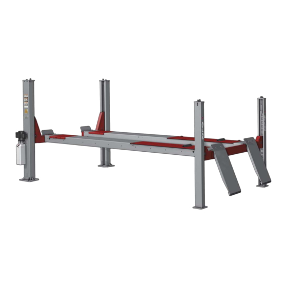
Product Description The lift is suitable for lifting motor vehicles having maximum weight as described in the nameplate on the power side column of the lift. All mechanical parts have been built in steel plate to make the frame stiff and strong while keeping a low weight. -
Page 12: Technical Specifi Cation
Technical Specifi cation Size And Main Features LIFT CAPACITY 14,000lbs (6400kg) Maximum raised height 76 3/4” (1950mm) Min. lowered height 7 7/8” (200mm) Runway length 223 1/2” (5679mm) Runway width 20” (510mm) Free width between runways 42 3/4” (1086mm) Width between two columns 116 3/8”... - Page 13 Pump Type Gear Flow rate 2.5 cm Continuous working pressure 160 bar Figure 3 – Lift Layout Technical Specification PVL14OF-EXT...
- Page 14 Hydraulic Power Unit Figure 4 – Hydraulic Power Unit Use wear proof oil for hydraulic drive, in conformity with ISO 6743/4 rules (HM class). The oil with features similar to those shown in the table is recommended. Test standards Features Value ASTM D 1298 Density 20°C...
- Page 15 Figure 5 -Hydraulic Plan Oil fi lter Manual lowering valve Gear pump Startup valve Motor Flow restrictor Non return valve Hydraulic cylinder Pressure overload valve Technical Specification PVL14OF-EXT...
- Page 16 WIRING INSTRUCTIONS To install power unit without relay: Connect L1 incoming power line to black pushbutton switch wire #9. Connect L2 incoming power line to white motor wire #5. Connect incoming green ground wire to green ground motor wire. If using overhead switch: Connect one overhead switch wire to black switch wire #3.
- Page 17 Figure 7 – Pneumatic Plan Filter/regulator must be equipped on the air circuit and the air pressure is to be set at 6-8bar. Filter/regulator is not supplied by the manufacturer if no special order. Technical Specification PVL14OF-EXT...
-
Page 18: Safety
Safety Read this chapter carefully and completely because it contains important information for the safety of the operator and the person in charge of maintenance. The lift has been designed and built for lifting vehicles and making them stand above level in a closed area. any other use is forbidden. - Page 19 Any use of the lift other than that herein specifi ed can cause serious accidents to people in close proximity of the machine. Risks For People All risks the personnel could run, due to an improper use of the lift, are described in this section.
- Page 20 Slipping Risks The risk of slipping can be caused by oil or dirt on the fl oor near the lift. Keep the area under and around the lift clean. Remove all oil spills. Electrocution Risks Avoid use of water, steam, and solvent, varnish jets in the lift area where electric cables are placed and, in particular, next to the electric panel.
- Page 21 6.10 Risks During Vehicle Lifting And Working To avoid overloading and possible breaking during lifting and working, the following safety devices have been used: • A pressure valve placed inside the hydraulic unit to prevent excessive weight. The maximum pressure valve has been preset by the manufacturer to a proper pressure.
-
Page 22: Installation
Installation Only skilled technicians, appointed by the manufacturer, or by authorized dealers, must be allowed to carry out installation. Serious damage to people and to the lift can be caused if installations are made by unskilled personnel. Always refer to the exploded views attached during installation. - Page 23 Installation Surface The lift MUST be installed on 3000 PSI concrete with the minimum thickness 6” and an extension of at least 1.5m from anchoring points. New concrete must be adequately cured by at least 21 days minimum. A level fl oor is suggested for proper installation. Small differences in fl...
- Page 24 Figure 14 – Cable Routing Diagram • With the openings in the rear beam side lined up with the runway ends, align the bolt holes in top of the beam with the slots in the runway ends. Bolt the runway to the rear beam using screws and washers as shown in fi...
- Page 25 Attaching Rear Columns To Rear Beam • Position a rear columns to the rear corner of the lift. • Place the latch rack into the back of the column as shown in fi g.17. Pay attention that the latch rack is offset from the center line of the thread stud.
- Page 26 Make sure each cable is routed in the pulley groove following the roping diagram fi g. 14. Failure to install the nylon bearings and bearings in the runways and beams will result in premature failure and void the warranty. Attaching Front Columns To Front Beams •...
- Page 27 • Slide the beam through the top opening of the column to the bottom of the column. Make sure that all sliders shown in the fi g.22 are in position. • Raise the beam and column assembly to the upright position and slide the beam under the runway end.
- Page 28 Installation Of Front Pulleys And Cables • Assemble the pulleys, bearings, pulley cover and other accessories into the front beams as shown in fi g.23. • Install each cable to the column top plate using the nuts and washers as shown in fi...
- Page 29 Figure 26 – Square And Diagonal Measurement Installation PVL14OF-EXT...
- Page 30 7.10.1 Anchoring Rear Columns • Move a rear column towards the rear beam until the sliders contact the back of column. Center the beam in the column. • Using the base plate as guide, drill each hole in the concrete approximately 120mm deep with the rotary hammer drill D.16.
- Page 31 7.12 Connection Of Hydraulic Hoses When routing the hydraulic hose, make sure that the hose is clear of any moving part, make sure to keep the hose and fi ttings clean from dust. • Clean the hoses and fi ttings. •...
- Page 32 7.13 Pneumatic System Connection The air hose must be cut square with no burrs. When routing the air tubes, make sure that the tubes are clear of any moving part. It may necessary to tie the hoses clear by using nylon tie straps or wire.
- Page 33 Figure 30 – Pneumatic Connection Diagram 7.14 Make The Electrical Hookup To The Power Unit The hookup work must be carried out by a qualifi ed electrician. Make sure that the power supply is right. Make sure the connection of the phases is right. The power unit must be kept dry. It is strictly forbidden to use 60Hz motor on 50Hz power supply.
- Page 34 7.15 Oil Filling And Bleeding DO NOT run power unit with no oil. Damage to pump can occur. If motor gets hot or sounds peculiar, stop immediately and recheck the electric connection. • Use the hydraulic fl uid recommended in the chapter 5.5. •...
- Page 35 7.16.3 Accessories Installation • Install the ramps on the rear runways using the ramp pin and two split pins 5X45 as shown in fi g.31. • Check and install all pulley covers on the corners of the beams. • Remove the space bar from the runways. 7.17 Check Before Start-Up During START UP procedure, observe all operating components and check for proper installation and adjustment.
- Page 36 7.17.2 Cable For Proper Installation There will be some initial stretching of the cables in the beginning. It will be necessary to re-adjust the cables a week after the fi rst week, then three months thereafter. Failure to do this will cause uneven lifting. •...
- Page 37 7.18 Check With Load WARNING: please follow carefully the instructions in the coming paragraph for avoiding damages on the lift. Carried out two or three complete cycles of lowering with the vehicle loaded and lifting and: • Repeat the checks provided for by 7.15. •...
- Page 38 To install the jacking beam on a 4 post lift, do as followings. • Lower the lift fully. • Lower the jacking beam all the way down. • Use a proper hoist equipment to place the jacking beam on rails inside runways of the lift.
- Page 39 • Without a vehicle loaded, depress the pedal of the pump to raise the jack at full stroke to check for the proper operation. • Check for the fi rst lock operation by lowering the jack to the fi rst lock position (about 444mm high) and then raising the jack to clear off the lock and in the meantime...
-
Page 40: Operation And Use
Operation And Use Never operate the lift with any person or equipment below. Never exceed the rated lifting capacity. Always ensure that all latches are engaged well before any attempt is made to work on or near the vehicle. Never leave the lift in an elevated position unless the safeties are engaged. - Page 41 Controls for operating the lift are: LIFTING BUTTON (1) • When pressed, the power unit is running and the lift can be raised to a desired height until the button is released. AIR CONTROL VALVE (2) • When pressed, the lock latches will be released so that the lift can be lowered.
- Page 42 8.1.2 Standing • Press the lowering handle to engage the nearest latch position; • Always ensure that the latch in each column is engaged before any attempt is made to work on or near the vehicle. 8.1.3 Lowering • Be sure the safety area is free of people and objects; •...
-
Page 43: Maintenance
Maintenance Only trained personnel who knows how the lift works, must be allowed to service the lift. To service properly the lift, the following has to be carried out: • use only genuine spare parts as well as equipment suitable for the work required;... - Page 44 Periodic Maintenance • Check hydraulic connections and hoses for leaks • Check air connections and hoses for leaks Daily pre- operation • Check safety lock audibly and visually while in operation • Check bolts, nuts and screws are tight • Check all cable connections, pins and bolts to insure proper mounting •...
-
Page 45: Troubleshooting
Troubleshooting A list of possible troubles and solutions is given below Trouble: Possible Cause: Solution: Check Power on to restore There is no power if necessary The electrical wires are Reconnect The lift does not work disconnected Check for correct voltage The circuit breaker are blown Replace... -
Page 46: Part List
Part List Figure 37 – General Part List General Part List Item Part Number Description Z72D110200A Power-side column Z72D110200B Front column Z72B110100 Rear column Z72D220000 Front beam A Z72D230000 Front beam B Part List PVL14OF-EXT... - Page 47 General Part List Item Part Number Description Z72D210000 Rear beam Z72D310000L Power-side runway Z72D320000L Off-side runway Z72D110300 Front top plate Z72D111200 Front latch rack Z72B111100 Rear latch rack Z72D821000 Wheel stop Z72D811000 Drive-on ramp Z72B810001 Z72D810003 Ramp roller pin Z72D810002 Ramp roller Z72A300101 Angle plate...
- Page 48 Figure 38 – Power-Side Runway Assembly Power-Side Runway Assembly Item Part Number Description Z72D311000L Runway weldment Z72B220005 Fastening plate B Z72B210002 Cable pulley Z72B310001 Pulley shaft Z72B310002 Cylinder pin Z72B310003 Nylon washer Z72D310004 Nylon spacer Z72D310007 Spring holder Z72D310009 Spring Z72D310010 Nylon washer Z72B310100...
- Page 49 Power-Side Runway Assembly Item Part Number Description Z72B310200 Cable retainer Z72D310300 Recess spacer Z72D310400 Rear slipping plate Z72D841000 Plate stop pin Z72B310012 Hose relief Z72B310014 Anti-derailment pin J63A332000 Nylon bearing unit Z72D310200 Recess cover 0213113 Split pin 5X50 0210052 Bush 4020/SF-1 0206031 Screw M6X10 0201062...
- Page 50 Figure 39 – Off-Side Runway Assembly Part List PVL14OF-EXT...
- Page 51 Off-Side Runway Assembly Item Part Number Description Z72D321000L Runway weldment Z72D310004 Nylon spacer Z72D310007 Spring holder Z72D310009 Spring Z72D310010 Nylon washer Z72D310200 Recess cover Z72D310300 Recess spacer Z72D310400 Rear slipping plate Z72D841000 Plate stop pin Z72B210002 Cable pulley Z72B220005 Fastening plate B Z72B310001 Pulley shaft J63A332000...
- Page 52 Figure 40 – Front Beam A Assembly Front Beam A Assembly Item Part Number Description Z72B210001 Pulley shaft Z72B210002 Cable pulley Z72B210003 Nylon spacer Z72B210004 Safety latch Z72B210005 Nylon roller Z72B210006 Latch shaft Z72B210007 Z72B210008 Fastening plate A Z72B210009 Cylinder joint Z71P211811 Spring Z72D222000...
- Page 53 Front Beam A Assembly Item Part Number Description Z72D220013 Pulley cover 0208007 Locking washer D.10 0210052 Bush 4020/SF-1 0205006 Washer D.6 0205022 Washer D.20 0212013 Seeger D. 10 0213035 Split pin 4X30 0201026 Screw M8X16 0205008 Washer D.8 0201059 Screw M10X16 0210058 Bush 2012/SF-1 0306333...
- Page 54 Figure 41 – Front Beam B Assembly Front Beam B Assembly Item Part Number Description Z72D231000 Beam B weldment Z72D220013 Pulley cover Z72D222000 Cable slack lever Z72B210001 Pulley shaft Z72B210002 Cable pulley Z72B210003 Nylon spacer Z72B210004 Safety latch Z72B210005 Nylon roller Z72B210006 Latch shaft Z72B210007...
- Page 55 Front Beam B Assembly Item Part Number Description Z72B210009 Cylinder joint Z71P211811 Spring 0201059 Screw M10X16 0210058 Bush 2012/SF-1 0201026 Screw M8X16 0205022 Washer D.20 0205008 Washer D.8 0212013 Seeger D. 10 0213035 Split pin 4X30 0205006 Washer D.6 0210052 Bush 4020/SF-1 0306333 Latch release cylinder...
- Page 56 Figure 42 – Rear Beam Assembly Rear Beam Assembly Item Part Number Description Z72D211000 Rear beam weldment Z72B212000 Cable slack lever Z72B210001 Pulley shaft Z72B210002 Cable pulley Z72B210003 Nylon spacer Z72B210004 Safety latch Z72B210005 Nylon roller Z72B210006 Latch shaft Z72B210007 Z72B210008 Fastening plate A Z72B210009...
- Page 57 Rear Beam Assembly Item Part Number Description 0212013 Seeger D. 10 0210052 Bush 4020/SF-1 0201059 Screw M10X16 0208007 Locking washer D.10 0205006 Washer D.6 0213044 Split pin 2X20 0205022 Washer D.20 0213035 Split pin 4X30 0201022 Screw M8X12 0205008 Washer D.8 0207041 Screw M8X12 0210058...
- Page 58 Figure 43 – Steel Cable Assembly Part List PVL14OF-EXT...
- Page 59 Steel Cable Assembly Item Part Number Description Z72D850100L Steel cable A L=10075 Z72D850200L Steel cable B L=5535 Z72D850300L Steel cable C L=11855 Z72D850400L Steel cable D L=4085 0205022 Washer D.20 0203012 Nut M20 Part List PVL14OF-EXT...
- Page 60 Figure 44 – Hydraulic Line Hydraulic Line Item Part Number Description 0306065 Rotation union 8-1/4 0306096 Rilsan hose 8X5.5 L=2600 0303002 90° fi tting 1/4 ZW4500 Hydraulic hose 5/16 L=4500 Part List PVL14OF-EXT...
- Page 61 Figure 45 – Latch Release Valve Assembly Latch Release Valve Assembly Item Part Number Description Z72B110207 Motor bracket 0306258 Air control valve 0305014 Plug 1/8 0206018 Screw M4X30 0306045 Quick union 8-1/8 0306087 Silencer 1/8 PVL14OF-EXT Part List...
- Page 62 Figure 46 – Rolling Jack Assembly - Optional Rolling Jack Assembly - Optional Item Part Number Description 0301030 Air pedal pump J07B110000 Jack base 0211015 Seeger D.8 J07B100100 Wheel 0511172 Nylon bush 1010 J07B100001 Wheel shaft 0511173 Nylon pin J07B120000 Base extension 0213109 Elastic pin 6X25...
- Page 63 Rolling Jack Assembly - Optional Item Part Number Description J07B000005 Shaft 0209010 Screw M6X10 J07B000100 Safety lock 1 J07B200000 Outer scissor arm J07B000001 Nylon upper slider 1 J07B300000 Inner scissor arm 0204004 Self-locking nut M8 0205008 Washer D.8 0201043 Screw M8X20 J07B000002 Nylon upper slider 2 0209030...
- Page 64 Figure 47 – Jack Hydraulic Cylinder Unit And Line Jack Hydraulic Cylinder Unit And Line Item Part Number Description ZY1090 Hose 1/4 L=1090 0306112 Quick union 8-1/4 0303020 45° union 0307022 Parachute valve 1/4 J07BY63100 Cylinder liner 8240TX-63-2 Piston J07BY63200 Cylinder shaft Part List PVL14OF-EXT...
- Page 65 Jack Hydraulic Cylinder Unit And Line Item Part Number Description 8240TX-63-3 Cylinder guiding cover 0306087 Silencer 1/8 0311005 Scraper 30X38X5/6.5 0305007 Guiding ring 30X10X2.5 0309022 O-ring 24X2.4 0312012 Gasket 63X47X18.4 0212005 Seeger D.20 Part List PVL14OF-EXT...
-
Page 66: Warranty
Warranty This item is warranted for fi ve (5) years on structural components, two (2) years on hydraulic cylinders, and one (1) year on electric or air / hydraulic power units from invoice date. Wear items are covered by a 90 day warranty. Our LIMITED warranty policy does not include a labor warranty.
Need help?
Do you have a question about the PVL140F-EXT and is the answer not in the manual?
Questions and answers