
Related Manuals for SCS PTC-IIex


Summary of Contents for SCS PTC-IIex
- Page 1 PTC-IIex The New Dimension in Data Transmission Technology Manual for Version 4.0 © Copyright 2003-2009 SCS GmbH & Co. KG...
- Page 2 AF and the PTT cables, and use the same power supply. The case of the PTC-IIex is at earth potential, and, in event of a short circuit, very serious internal damage to the PTC-IIex can occur if this advice is not followed.
- Page 3 Special Communications Systems Model PTC-IIex Federal Communications Commission (FCC) Statement This equipment has been tested by a FCC accredited testing facility and found to comply with the limits for Class B Digital Device, persuant to Part 15 of the FCC rules. These rules are designed to provide reasonable protection against harmful interference in a residential installation.
-
Page 4: Table Of Contents
Command structure ............. 20 Menus ................. 20 Simultaneous STBY mode .......... 21 Specialities of the PTC-IIex ......... 21 Remote commands ............. 22 PTC-Mailbox ............... 23 5.7.1 Multiple file operations ..........24 ... - Page 5 5.8.2 The NAVTEX System in Detail ........28 5.8.3 Operating the NAVTEX Processor ......29 5.8.4 Notes about NAVTEX practice ........30 5.8.5 AMTEX ............... 30 GPS ................30 5.9.1 Connecting the GPS receiver ........
- Page 6 Table of Contents 6.32 CYcle................51 6.33 DAte ..............52 Remote 6.34 DD ................52 6.35 DELete ............52 Remote 6.36 ..............52 Remote 6.37 Disconnect ..............53 6.38 EQualize ..............
- Page 7 6.75 PT ................70 6.76 PTChn ................. 70 6.77 ..............70 Remote 6.78 QRTChr ..............70 6.79 Read ............... 70 Remote 6.80 RELOad ..............71 6.81 REMote ............... 71 ...
- Page 8 LED functions .............. 99 Fax:-menu commands..........100 The PTC-IIex as COMPARATOR-MODEM ....101 PTC-IIex with 300 baud HF Packet ......101 Modem commands in detail ........101 8.7.1 Amfax ................ 101 ...
- Page 9 9.6.36 TXLevel ..............129 9.6.37 Unproto ..............129 9.6.38 USers ................ 129 Hostmode ..............131 10.1 The PTC-IIex Hostmode ........... 131 10.2 Modern Times ............132 ...
- Page 10 Table of Contents 10.3 DAMA ................ 133 10.4 Commands ..............133 10.4.1 C ................133 10.4.2 D ................134 10.4.3 F ................134 10.4.4 G ................134 10.4.5 I .................
- Page 11 10.8.6 Start of the CRC-Hostmode ........148 10.8.7 Recommended baudrate .......... 149 10.8.8 Example source code for CCITT CRC16 (HDLC) ..150 PSK31 ..............152 11.1 General ..............152 11.2 Activation and use of the PSK31 terminal ....
- Page 12 Table of Contents 13.4.6 Led ................165 13.4.7 Quit ................165 13.4.8 RUN ................165 Circuit Description ..........166 14.1 The Processor section ..........166 14.2 The shortwave modem with signal processor ... 166 ...
- Page 13 List of Figures and Tables List of Figures Figure 3.1: The PTC-IIex rear panel..........9 Figure 3.2: RS232 Connections ............ 10 Figure 3.3: Connection to the transceiver........11 Figure 3.4: Connections to the transceiver (5 PIN DIN)....12 Figure 15.1:...
- Page 14 List of Figures and Tables...
-
Page 15: Introduction
20 ms is required. Therefore any transceiver capable of AMTOR can also be used for PACTOR. To operate the SCS-PTC-IIex you need a computer or a simple terminal that provides an serial interface compatible with the RS232 (V24) standard. If you use a computer you need a appropriate terminal program to operate the serial interface with the following parameters: 8 bit, no parity and 1 stopbit. -
Page 16: Typography
1 Introduction All descriptions in this manual refer to the default settings of the PTC-IIex. This is very importand especially with respect to the freely definable control characters (ESCAPE- character in section 6.39 on page 54, BREAKIN-character in section 6.12... -
Page 17: Table 1.1: List Of Programs
Possible, but no special support provided. Not possible with this software. • We are frequently asked “What is the best program for the PTC-IIex?”. This question cannot be answered easily as it is similar to someone asking “What is the best car?” or... -
Page 18: Version Numbering
“What is the best operating system?”. It’s a question of personal preference and depends on the application. If HF email is your application for your PTC-IIex, it may not be necessary to study Table 1. In most cases, your HF email service provider supplies or recommends the appropriate software for their particular service. -
Page 19: Pactor-Iii
• CCIR 491-Number-SelCalls (4- and 5 characters), as well as WRU-identifier and Answerback for comfortable access to SITOR-coast-stations. For permanent usage of the extended firmware features you need a license key from SCS. Without this key you can test the extended features for 20 connects. Refer to LICENSE command chapter 6.46... -
Page 20: Easytransfer
• Easy embedding and configuration under all common operating systems. • No "timeout"-problems on PPP and TCP/IP. As host system for the PACTOR-IP-Bridge SCS has developed the PTC-IInet. A detailed manual for the Professional Firmware can be found on our homepage http://www.scs-ptc.com. -
Page 21: Customer Support
2 Customer Support Chapter 2 2 Customer Support If you have questions, problems, proposals, or comments relating to the PTC-IIex or PACTOR, please contact the following address. Special Communications Systems GmbH & Co. KG Roentgenstrasse 36 63454 Hanau Germany Fax.: +49 6181 23368 Order Fax.: +49 6181 990238... -
Page 22: If You Have A Problem
2 Customer Support If you have a problem If a problem occurs and it’s necessary to send your SCS product to maintenance, please take care of the following: • Package the device with care. Use suitable and enough packaging material. -
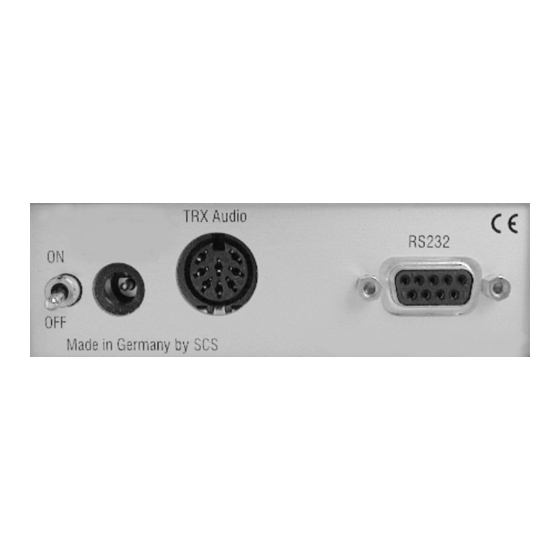
Page 23: Installation
The PTC-IIex rear panel. Power supply The PTC-IIex has two inputs for its power connections which can be used alternatively. Either connect via the DC-in supply socket at the rear of the unit, or via the connector for the short-wave transceiver (Audio). Both connections are decoupled with diodes and protected against reverse polarity. -
Page 24: Connections To The Transceiver
The PTC is connected to the transceiver via an 8 PIN DIN socket. PIN 1: Audio output from the PTC to the transmitter. The PTC-IIex supplies a pure audio signal to the microphone input of the transceiver. The output amplitude can... -
Page 25: Figure 3.3: Connection To The Transceiver
Black Green Brown Table 3.1: Cable Colors: 8-pole DIN-cable The socket is wired as follo ws (Viewed from the rear of the PTC-IIex). Pin 1: Audio ou tput from the PTC to the transmitter. Pin 2: Ground. Pin 3: PTT output. (to transmitter PTT line) Pin 4: Audio input from the receiver to the PTC. -
Page 26: Connection To Icom Transceivers
3 Installation It is possible to use a 5-pole DIN plug if an 8 pin is not available, or the extra functions are not required. If a 5 pin DIN plug is used, then the connections are as shown: Pin 1: Audio output from the PTC to the transmitter. Pin 2: Ground. -
Page 27: Connection To Kenwood Transceivers
3 Installation 3.3.2 Connection to Kenwood transceivers: Most Kenwood transceivers that use 13 pin DIN plug (ACC2) can be connected this way: Signal Color Kenwood PIN 2 white PIN 4, 8, 12 PIN 3 yellow PIN 9 AF-OUT PIN 1 violet PIN 11 AF-IN... -
Page 28: Amplitude Adjustment
Table 3.9: YAESU 6 pin Mini-DIN 3.3.4 Amplitude Adjustment The PTC-IIex output amplitude has to be adjusted very carefully to the connected transceiver. If you don’t pay attention on this item a signal much too wide will be the result! The output amplitude are adjusted separately depending on the modes FSK (PACTOR-I, AMTOR, RTTY, etc). - Page 29 3 Installation With proper settings the peak envelope power will nearly be equal to the maximum output power of the TRX. In this case the average power will approximately be the half of the maximum power, so also continuous operation will not cause problems at all. Don’t be confused as many modern TRX only display the peak envelope power.
- Page 30 3 Installation...
-
Page 31: Led's
4 LED’s Chapter 4 4 LED's The SCS PTC-IIex is equipped with 8 LED´s to display the most essential status information and a fifteen LED tuning indicator. The meaning of the LED´s is explained below. PACTOR-I / PACTOR-II: This LED shows the PACTOR-mode when connected or in LISTEN-mode. -
Page 32: Pactor-Iii
Besides the tuning-display it also serves to inditace several system conditions: Autobaud: After power-up the PTC-IIex tries to detect the baudrate of the terminal connected to. It indicates this with a LED running from right to left and opposite. Loading: After a firmware update the firmware needs to be copied to the 32 bit wide SRAM (loading). -
Page 33: Ptc-Firmware
Chapter 5 5 PTC-Firmware With the PTC-IIex it is nearly possible to configure everything. In the manual always the default settings are assumed! If you have changed these settings you must keep this in mind while reading the manual. This is very important in case of the control characters which can be freely defined (CHANGEOVER character in chapter 6.19... -
Page 34: Command Structure
The short form of the SERBaud command is SERB. Menus The PTC-IIex commands are combined into different function groups, so called menus. The different menus are the following: • Packet-Radio • Audio functions •... -
Page 35: Simultaneous Stby Mode
BC. Specialities of the PTC-IIex As the PTC-IIex is a single port unit some items have to be cared of when choosing Packet-Radio operation or the HF modes, especially that simultaneous operation of Packet and the HF modes in not possible. -
Page 36: Remote Commands
5 PTC-Firmware condition at program start. The same can be done for de-initialization at program shutdown. • The PR command will be ignored with an existing PACTOR connect. • The PT command is ignored with an existing Packet-Radio connect. Remote commands Some PTC commands are also available for the distant station via the HF link. -
Page 37: Ptc-Mailbox
5 PTC-Firmware PTC-Mailbox The PTC-IIex contains its own built-in mailbox. The mailbox files are stored in static RAM and remain there even when the power supply is turned off. The maximum allowable file length and the number of files in the mailbox is only limited by the amount of free memory. -
Page 38: Multiple File Operations
5 PTC-Firmware A list of the commands follows: Command Short description Reference Help Help !! Chapter 6.44 BEll Call the Sysop. Chapter 6.11 Read the main directory OF THE MAILBOX. Chapter 6.36 List Gives a list of files within a directory. Chapter 6.48 Check... -
Page 39: The Ptc Mailbox For Packet-Radio
It is also possible to use it in smaller general mailbox systems as a stand-alone solution. The PR mailbox in the PTC-IIex can be viewed as a self contained TNC in the PTC. This virtual mailbox TNC contains its own callsign, the BBS-MYCALL. The user can reach the PR mailbox in the PTC-IIex by connecting to the BBS-MYCALL of the PTC-IIex. -
Page 40: Passing Pr Connects To The Mailbox
5.7.5 Passing PR connects to the mailbox The USers command in the pac:-menu allows any incoming PR connect to be passes over to the PTC-IIex PR-mailbox. To do this USers has to be set to 0. This will allow for... -
Page 41: Properties Of Mailbox-Commands
(e.g. automatic de initialising with Y0 in GP) the PTC-IIex can be brought to a condition where a connect using the normal MYCALL (i.e. without the -8) will be transferred to the mailbox. This is useful, as many potential users would use the normal MYCALL to connect to the PTC-IIex. -
Page 42: The Navtex System In Detail
• A memory buffer is available without using an external computer, as the NAVTEX processor uses the PTC-IIex internal mailbox as a message store. It automatically lays down, if not already there, a subdirectory called NAVTEX in the PTC-box. Data written into the mailbox by the NAVTEX processor can be accessed via PACTOR or Packet-Radio. -
Page 43: Operating The Navtex Processor
PTC-IIex multitasking environment. When activated, the NAVTEX processor lays down a directory with the name NAVTEX in the PTC-IIex mailbox, and stores all incoming NAVTEX messages there. The name of the message author is given as "AUTO-NAV". The NAVTEX processor gives the complete four figure message header as well as the plain language name of the type of message. -
Page 44: Notes About Navtex Practice
The "Global Positioning System" (GPS) has very quickly become a standard for all areas that require exact positional information e.g. shipping, in-car navigation systems etc. Today, GPS receivers are cheaply available and widely used. The PTC-IIex offers the possibility to link the GPS technology with PACTOR, and also to PR. It now becomes... -
Page 45: Connecting The Gps Receiver
9 of the RS232 socket. (Ground is connected to pin 5. Do not forget the ground connection!) SCS offers a special Y cable which splits the leads to and from the RS232 socket on the PTC-IIex so that two separate DIN-9 RS232 standard sockets are available. By using the Y cable, it is possible to connect a GPS receiver and a PC to the PTC-IIex without needing a soldering iron. -
Page 46: Robust Hf-Packet
“statics” will destroy a many seconds long packet. Just one missing bit leads to a repeat of the whole transmission. To overcome this problem SCS has developed a new class of robust modulation types especially for Packet-Radio. As a special feature for all the variants of this “Robust-PR” a completely new synchronization algorithm with tracking properties that were not possible before has been realized. -
Page 47: Pactor Duplex And Data Transparency
The PACTOR duplex is activated with the new command PDuplex (refer to chapter 6.70, page 67). The automatism works with the following relatively simple algorithm: 1. If the PTC-IIex is the information sending station ( ISS), that means controls the keys, the PTC-II automatically executes a CHANGEOVER, if his transmission buffer is empty (that means no data to be sent are available). -
Page 48: Application For Pactor-Duplex
- e.g. in the Autobin mode via PACTOR – without the detour using 7PLUS or other coding mechanisms. If a file shall be transmitted to a friend using the PTC-IIex too, both PTC-IIex are switched to PACTOR Duplex. Using a WA8DED hostmode program all features available for PR can be used on the PACTOR channel (usually channel 4) as well–... -
Page 49: Audio Functions
For special processing and filtering of Audio signals (Audio from the Transceiver) the PTC-IIex presents its own submenu - the so called Audio-Denoiser menu, aud:-menu. The PTC-IIex is thus also suitable for SSB operation (automatic notch filter) and for CW listening (Automatic peak-filter, CW-filter) and has very useful options. The Audio is presented to the PTC as usual via PIN 4 of the 8 PIN HF radio connector, so that no changes compared with normal RTTY/PACTOR operation are required. - Page 50 Another comfortable way to initiate a CHANGEOVER in the hostmode is to use the command HCr (refer to chapter 6.43, page 55). If HCr is 1 the PTC-IIex executes a CHANGEOVER for each line feed at a blank line. That’s convient for direct QSOs.
-
Page 51: Commands
6 Commands Chapter 6 6 Commands ACheck (AMTOR Check) Default setting: 30 Parameter: X 0... 100, SNR for AMTOR Packets. This command allows a much sharper error checking than is possible with previous AMTOR systems. By using the analogue information from the A/D converter, it is possible to estimate the Signal/Noise ratio of the AMTOR blocks or the AMTOR CS signals (noise in this sense meaning all unwanted signals). -
Page 52: Apower
It is naturally still possible to receive PACTOR connects, to read PACTOR QSO's, AMTOR FEC and NAVTEX transmissions. With the SCS-PTC-IIex it is possible to use upper and lower case letters in AMTOR! The PTC uses the PLX-APLINK convention to transfer data. It is thus completely APLINK compatible, and can read messages from, and send messages to the APLINK system using both capitals and lower case. -
Page 53: Aqrg
6 Commands If AP is set to 200, the PTC-IIex will never set the PSK output level below 200 mV. That means that with a PSKA value of 140 (setting of the maximum PSK amplitude value, refer to the PSKAmpl command, chapter 6.73, page 69) and an AP of 200 the power never will be reduced. -
Page 54: Audio
Bandwith, Center, CWfilter, DD, Delay, Help, Invert, Notch, Peak, Quit, Through, TOne. The usual commands of the PTC-IIex are no longer available for use. You can leave the aud:-menu with the Quit or DD command. For a detailed description of the audio commands refer to chapter 7, page 91. -
Page 55: Baudot
6 Commands The block number count enables external software for example, to perhaps recognize any block loss that may occur during data transfer, and in such an event, to undertake damage limitation measures. Such measures may, for example, replace the missing block by an empty block. -
Page 56: Bell
6 Commands With the ARX command the reception of AMTOR-FEC and NAVTEX can be disabled independent from the setting of BC refer to Table 6.1 on page 40) 6.11 BEll Remote Default setting: 1 Parameter: SYSOP calling disabled. SYSOP calling enabled. Use of this command causes an intermittent beep (approx. -
Page 57: Boot
6 Commands 6.14 BOOT Use BOOT to load the PACTOR firmware via the serial interface into the RAM. This is mainly used for testing during software development. BOOT only works in connection with a special load program and can not be used with a normal terminal program. 6.15 Default setting: 0 Parameter:... -
Page 58: Check
6 Commands 6.17 CHeck Remote (from the remote side entering C is enough, see also Connect, chapter 6.22, page 45) Default setting: 10 Parameter: 1... 100, number of mails to be listed. List private mail only. CHeck without argument lists the newest 10 public mails of the mailbox. With a numerical argument between 1 and 100 it is possible to define the quantity of mails to be listed. -
Page 59: Clr
6 Commands Using <Ctrl-Z> (entering <Ctrl> <Z>) as a CHANGEOVER characters is defined with the command CHO 26. Illegal values are 13 (CR), 32 (Space), 30 (IDLE), 17 (XON), 19 (XOFF), and other previously defined special characters. 6.20 Remote Deletes the transmit buffer. Everything that is contained in the transmit buffer, which has not yet been transmitted, is deleted. -
Page 60: Robust-Connect
3.1, the Robust Connect has only been available as a part of the Professional PTC-IIex firmware. With version 3.1 Robust Connect will also be available as a part of the "normal" firmware, but restricted to outgoing calls/connects, i.e. only systems... -
Page 61: Contype
Parameter: 0 Accepts no connects Accepts only normal connects Accepts only robust connects Accepts all connects CONType defines which connect types the PTC-IIex accepts while in standby mode and with this leadss to a connection to be established. 6.24 CSDelay Remote Default setting: 5 1... -
Page 62: Ctrlchr
6 Commands 6.26 CTrlchr Default setting: 22 (Ctrl-V) Parameter: 1... 127, decimal ASCII code of a character. Defines the Ctrl character. If the Ctrl character is immediately followed by a-z (or A-Z), the PTC will transmit a control code (ASCII 1-26) via HF channel. With this simple convention, control characters that are used by your own terminal can also be sent to the other station. -
Page 63: Cwmoni
Parameter: 40... 400, Start receiving speed in LpM. The CWTerm command activates the CW terminal of the PTC-IIex. The actual speed depends on the CWSpeed parameter. The keying takes place using the PTT line, as with the CWID. The FSK line remains constant on the Mark frequency. The AFSK signal amplitude is also keyed. - Page 64 6 seconds. This has the advantage that user may continue writing after the buffered text is sent, without having to press any other key. The renewed blocking of the transmitted is shown by the PTC-IIex with the message '>>>' written to the Delayed Echo-window.
-
Page 65: Cwweight
6 Commands to set the correct speed, then press <Ctrl-F> to keep this setting. The operation with a fixed speed has definite advantages with weak signals, or signals with heavy fading. The decoder withstands speed errors of 40 percent without problem, so that even with a fixed speed setting, virtually no reading errors are found. -
Page 66: Date
Faulty inputs cause incorrect programming of the clock chip! From 01.01.1990 up to 31.12.2089, the day of the week is automatically calculated from the date. Thus your PTC-IIex is well equipped for the future. Required date Sunday 24th March 2005. cmd: DA 24.03.05 <Return>... -
Page 67: Disconnect
6 Commands If DIR contains as a parameter the name of a subdirectory, then the contents of this subdirectory will be listed, e.g. DIR test shows all files in the subdirectory 'test'(refer also to LIst in chapter 6.48, page 57) DIR without parameter appears similar to below. -
Page 68: Equalize
AGain, AResolut, FResolut, SResolut, FSKBaud, Deviation, MBaud, SMode, HSynch, JSynch, TXcomp. All other (normal) commands of the PTC-IIex are no longer available for use in the fax:- menu! You can leave the fax:-menu with the Quit or the DD command. -
Page 69: Fec
30... 3000, AF output voltage (peak to peak) in mV. This serves to set the Audio output (transmitted signal) of the PTC-IIex for all non PSK modes. Before this value is changed, the PSK amplitude should have been correctly set (see PSKAmpl command, chapter 6.71, page 67). -
Page 70: Lfignore
The LICENSE command is to enter or to readout (if already entered previously) the License key which enables extended (professional) firmware functions. The following messages will be returned by the PTC-IIex, depending on licensing status: If the license is invalid: LICENSE: NOT OK, XY TRIAL CONNECTS REMAINING Whereby XY is the number of remaining test connects. -
Page 71: Lin
6 Commands • PACTOR connections to be established using the HAYES command interpreter. • PACTOR connections to be established using the Free-Signal-Protocol. Only these operating conditions are decreasing the trial counter, which represents the remaining quantity of test connections using the feature respectively. As soon as the trial counter reaches zero, the features are not available any more unless a valid license code is entered. -
Page 72: Pactor-Iii
6 Commands and displayed: [CONNECT-FRAME: CALL], e.g. [CONNECT-FRAME: DL6MAA] means that a station is trying to connect to DL6MAA. With poor signals it is possible that the CALL is displayed only partially because it couldn´t be decoded correctly. Parameter 5 will be accepted by the Listen command (PACTOR monitor operation). If the listen parameter is set to 5, only PACTOR-I transmissions are monitored. -
Page 73: Log
6 Commands 6.51 Remote This command reads the PTC log entries. The last 16 PACTOR/AMTOR contacts are displayed (except Unproto contacts). The Log entries can only be erased with a RESTart (a total reset). The following extra information in the callsign field is also available: PACTOR-I (Sysop call) PACTOR-II (Sysop call) PACTOR-I (Rx call) -
Page 74: Mark
Parameter: 300... 2700, frequency in Hz. Allows the adjustment of the mark frequency of the PTC-IIex in 1 Hertz steps (internal resolution 0.25 Hz, using DDS). The frequency chosen with the MARk command is only used when the TOnes parameter is set to 2 (refer to TOnes command, chapter 6.95, page 81). -
Page 75: Maxsum
6 Commands 6.57 MAXSum Default setting: 30 Parameter: 5... 60, maximum count for memory ARQ. MAXSum is the timeout value for the memory ARQ counter. It determines the maximum number/sum of faulty packets that are summed up. If MAXSum is exceeded, the sums are deleted, since it can be assumed that crude errors have entered the sum, and that further summation of the packet will not restore it. -
Page 76: Monitor
Level II compression turned on, even when transmitting 7Plus, binary files or graphics. No manual intervention by the operator is required, as the PTC-IIex will switch automatically to uncompressed ASCII transmission for individual packets, if necessary. -
Page 77: Mycall
Default setting: 3 Parameter: The PTC-IIex behaves as a Level I controller. The PTC-IIex behaves as a Level II controller, and will switch to PACTOR-II when the other station is so fitted. The PTC-IIex behaves as a Level III controller, and will switch to PACTOR-III when the other station is so fitted. -
Page 78: Navtex
HELP NAVTEX <Return> If the command NAVtex is given without argument, the PTC-IIex displays the present configuration of the NAVTEX processor. The two most essential things to be set up are: •... -
Page 79: Choice Of The Message Area Codes
6.65.4 Choosing the message latency time A somewhat advanced setting possibility allows the PTC-IIex to decide after what time period the message is no longer valid. This command is the argument "DAYS" which may follow the NAVtex command. It can contain a number between 0 and 365. This sets the time the message will be counted as valid. -
Page 80: Amtex
Case switching enabled. This command only refers to the AMTOR side of the PTC! The SCS-PTC supports the PLX-APLINK convention for case switching. This means that AMTOR files from the PTC, with upper and lower case letters, may be distributed throughout the worldwide APLINK network. -
Page 81: Off
(refer to chapter 9, page 113). The PACket command can also have a single command from the pac:-menu as argument. As with the other sub menus of the PTC-IIex, it is also possible to pass through direct commands this way. -
Page 82: Position
Default setting: none Parameter: NMEA Requests NMEA raw-data. When a GPS receiver is connected to the PTC-IIex, its possible to readout the actual position using the POSition- command. The position information normally has the following format: GPS POSITION REPORT ------------------- Latitude: 50°... -
Page 83: Pskampl
(Please pay particular attention that the chosen frequency is really free. PTC-IIex links operate even when the signals are so weak as to be virtually 'non existent'!). Use U 3 <Return>to start the Unproto mode 3 (100 Bd DBPSK). -
Page 84: Ptchn
6 Commands 6.75 Returns to PACTOR from the AMTOR, RTTY, PSK31 or CW modes. Activates the PACTOR input prompt (cmd:). 6.76 PTChn Default setting: 4 Parameter: X 1... 31, Hostmode channel for PACTOR. Defines the Hostmode channel for PACTOR, which can then only be used by a Hostmode program on the channel defined here. -
Page 85: Reload
The REMote command should be set to 0 for 7plus transmission. Also, directly after a connect, or CHANGEOVER to receive, the PTC-IIex is internally at the beginning of a new line, and thus processes the directly following // sequence as a remote control sequence, this limitation of only being accepted at the beginning of a new line increases the data transparency quite considerably. -
Page 86: Restart
PTC-IIex. This is for example the case if the PTC-IIex (and the whole station) is switched on and off by a timer. Also if you want to make the PTC-IIex react on a hostmode program after switching on you have to set the baudrate to a fixed value. -
Page 87: Sfile
(ESCchr). It is also possible to force the PTC-IIex to reset its SERBaud value to AUTO. As the PTC-IIex has no switches to let the user express the intention to reset to AUTO, a special procedure is used to achieve this. -
Page 88: Show
6 Commands 6.88 SHow Remote Default setting: None. Parameter: A (ALL) displays all parameters. (CHARACTERS) displays all the control character settings. (PARAMETERS) displays the system parameters. (BUFFER) repeat of the last 12288 characters entered. ATTENTION: SHow B is disabled for Remote operation. The SHow command without parameters displays the present link parameters. -
Page 89: Space
The ZCZC/NNNN autostart can be activated setting the squelch parameter to a value between 100 and 200. If the squelch value is set to 140, the PTC-IIex operates with the ZCZC/NNNN autostart and additionally with the normal analog squelch of 40 (value minus 100). - Page 90 The status information is processed totally independent from the current XON/XOFF state of the serial interface. In status mode 2, the PTC-IIex has an automatic status output. This means that the status no longer needs to be regularly polled by the terminal program. Instead, every status change causes the status information automatically to be given.
-
Page 91: Table 6.3: Ptc Status Information, Bit 0-2
RF channel busy. Table 6.4: PTC status information, Bit 4-6 In STBY condition the PTC-IIex analyzes the HF channel and differs between busy and free. A busy channel is defined as all signals that are audibly distinctly different from noise, but, however, having a speed < 250 Baud. Packet-Radio (300 Baud) is virtually ignored. -
Page 92: Systest
Split screen with command prompt recognition. Split screen also for Packet-Radio. With this command it is possible to make the PTC-IIex support split screen terminals. In simple terminal mode text is not sent to the terminal when the PTC receives commands from the user. -
Page 93: Table 6.5: Code Byte Description
Setch to 2 if one wishes to transmit data via channel 2. (If for instance an external link from the PTC-IIex has been automatically given channel 2 and one wanted to write a text to that other station.) Terminal programs that fully support Term 5 must therefore also automatically administrate the Setch command. -
Page 94: Time
6 Commands Bits 5-7 contain coded information about the prompt sort: Bit 7 Bit 6 Bit 5 Prompt Bits 0-4 Not allowed cmd: 0=cmd, 1=AMTOR, 2=MONITOR, 3=RTTY, 4=CW, 5=PSK31 Not allowed always 0 sys: always 0 aud: always 0 pac: present input channel (0-31) Not allowed always 0... -
Page 95: Tnc
PTC-IIex can always be operated with the TNC set to 1. 2. The PTC-IIex shows the same behavior as in the TNC 1 mode, but additionally the prompt will be altered to asterisk *, i.e., the PTC answers to a ESC character not with the cmd:-prompt but with the asterisk. -
Page 96: Tones
Standard PACTOR-III tones 1400/1600 Hz PACTOR-III tones 1600/1800 Hz The TOnes command allows the PTC-IIex to be switched between two preset Low tone or High tone standards, or to freely adjustable tone frequencies. The two tones are used for FSK as well as PSK operation. -
Page 97: Txdelay
6 Commands A description of the parameter follows: Low tones 1400 Hz = Mark frequency. 1200 Hz = Space frequency. If TR = 0 (default), in RTTY and AMTOR the TRX must be set to USB operation. High tones 2100 Hz = Mark frequency. 2300 Hz = Space frequency. -
Page 98: Umlauts
6 Commands 6.99 UMlauts Default setting: 1 Parameter: No umlaut in Huffman. German umlauts in Huffman. With UMlauts, the umlaut convention (for German umlauts) for Huffman coding is activated or de-activated. The coding table is described in the MOde command. Usually the activated umlaut convention is used, as this considerably increases the transmission speed of German plain-language texts. -
Page 99: Update
If no argument is given, then the PTC-IIex uses the mode that was last used, or the default setting. The actual mode is shown on the LED status field. The Unproto mode may be terminated with a QRT character, a Disconnect. It is always possible to abort a unproto transmission using the command DD. -
Page 100: Usos (Unshift On Space)
BBS contents. 6.105 Version Remote Shows a short version and copyright message: PTC-IIex System / written by H.-P. Helfert (DL6MAA) Version V.3.7 (C) 1994-2006 SCS GmbH – Germany BIOS: Version 1.90 detected Packet Radio Port: SCS – DSP MULTI MODEM detected 6.105.1 Displaying the most important modem properties... - Page 101 4 = SCS-FSK-modem (direct-FSK) 5 = SCS-DSP-modem (multimode) 2. digit: Modem attribut for modem on port 1 A = standard modem (e. g. SCS-DSP-Modem-I) D = SCS-DSP-Modem-II 3. and 4. digit as 1. and 2. digit, but for port 2.
-
Page 102: Write
The XUser command is used to manage the user list. The PTC-IIex firmware allows to define user specific access priorities, i.e., that it is possible to define in a user list if for example the user DK9FAT is permitted to use the... - Page 103 6, because in PR the length is limited to 6 characters by the protocol. Callsigns extensions, e.g. F/DL6MAA/M are inadmissible and not useful because of incompatibility with the PR protocol. The PTC-IIex cuts all characters appearing after a special character in the callsign automatically. From the entry DL6MAA-10 is...
- Page 104 Sets the priority for the callsign CALLSIGN to the value xxxx. The numbers 0-9 are allowed for each character within xxxx, e.g. 1330. No spaces between the numbers are allowed. If less than 4 digits are defined, the PTC-IIex automatically adds a 0 at the missing positions. The PTC-IIex confirms with “OK”.
-
Page 105: Audio
CWTerm, chapter 6.30). The Center command also adjusts the audio frequency of the CW-Terminal (chapter 6.30) of the PTC-IIex send and receive sides. CWfilter Activates the CW-filter, using the center frequency set by the Center command, and the bandwidth set by the Bandwidth command. -
Page 106: Delay
7 Audio Delay Default setting: 100 Parameter: 0... 1500, delay in ms. Defines the delay time between the Audio-IN (socket X4, PIN 4) and Audio-OUT (socket X4, PIN 1) signal. Help Lists all commands used in the aud:-menu. Invert Default setting: 3000 Parameter: 3000... -
Page 107: Tone
7 Audio 7.12 TOne Default setting: 1000 Parameter: 1... 4000, frequency in Hz. 1... 4000, frequency in Hz. Starts the sine wave generator. The frequency required is given as an argument for the command. The range covers 1 Hz to 4000 Hz with a resolution of 1 Hz. The command without an argument delivers a tone of 1000 Hz. - Page 108 7 Audio...
-
Page 109: Fax
Chapter 8 8 FAX General Information In addition to the normal teletype modes the PTC-IIex supports the following modes; FM-FAX (Shortwave), AM-FAX (Satellites), SSTV (All present standards) and NFSK- Demodulation for decoding various shortwave teleprinting methods. The algorithms used here, profit from the relatively high computing power of the PTC- IIex and allow the system to easily reach the theoretical limits regarding definition, filter performance and resistance to interference in all picture operating modes. -
Page 110: Fm-Fax
The pixel-rate from Meteosat 5 is 3360 pixels per second - 4 lines are transmitted per second. The resulting bandwidth (relating to the appropriate Nyquist filtering) is ± 1680 Hz or a total of 3360 Hz. The PTC-IIex allows the maximum possible resolution of the Meteosat signal to be displayed. -
Page 111: Sstv
8 FAX for FM-FAX reception, so that the correct relationship between brightness and frequency information is maintained. (If the wrong sideband is chosen then the pictures are inverted, i.e. black lines are drawn white and vice-versa). 8.2.3 SSTV With use of a computer creeping into virtually every shack, the SSTV mode has changed from a technical challenge for a few specialists, to a relatively wide-spread and amusing amateur radio pastime. -
Page 112: Fax And Sstv With Jvcomm32
After XOFF the PC could still send about 5000 bytes without causing a buffer overflow. Output data rate: exactly 1/20 * Mbaud rate A skew correction usually is not necessary because the PTC-IIex quartz is adjusted up to some ppm. -
Page 113: Reference Of Databytes Concerning The Ptc
• LED´s of the tuning indicator. Data byte 0=left-corner, data byte 240= right-corner. Important Note: The JVComm transmission routine of the PTC-IIex is supported from the JVComm32 version newer than 0.96c beta by JVComm32. It is possible to download JVComm32 in the internet from the JVComm-WWW-Site http://www.jvcomm.de... -
Page 114: Fax:-Menu Commands
Modem command, refer to the MBaud-Parameter command. The MODEM operation of the PTC-IIex can be ended at any time by inputting a byte with the value 255 (dec.) via the RS-232 port. It is essential to use the correct baud rate (see MBaud-command!). -
Page 115: The Ptc-Iiex As Comparator-Modem
0 to 255. Measured values greater than 255 are limited to 255 by the PTC-IIex. (The data width is limited to 8 bits by the serial format.) With an AF input amplitude of 500 mV, and a standard setting of AGain (50), the PTC-IIex gives an output value of 255. -
Page 116: Fmfax
The output values reach from 0 to 255. Measured values smaller than 0 are output as 0. Values greater than 255 are limited to 255 by the PTC-IIex. The center frequency is exactly 1900 Hz. With a frequency of 1900 Hz as AF input, the PTC-IIex always gives out the appropriate value of 128. -
Page 117: Jvfax
JVFAX program to signal the synch pulse. Bits 0 and 1 are set to 1 in the resting state. As soon as the PTC-IIex recognizes a correct synch-pulse on the 1200 Hz frequency, it sets the bits 0 and 1 to 0 for the time the synch-pulse occurs. -
Page 118: Jvcomm
PIN 6 of the RS-232 interface. It has traveled via a trigger stage, which gives a 1-bit digitized signal as output. If the PTC-IIex measures an input frequency of greater than 1900 Hz, then PIN 6 goes to -10 Volts. For frequencies lower than 1900 Hz, the PTC-IIex sets PIN 6 to +10 Volts. -
Page 119: Pr300
166.7 ms (for example when in FM-FAX only white must be transmitted), then the PC program must send data to the PTC-IIex at least every 166.7 ms, so that the transmitter stays on transmit. By using this system, an extra PTT-command is not required. -
Page 120: Transmission In Fm-Fax/Fsk/Sstv-Modem Mode
The transmitted data controls the instantaneous frequency of the output signal. For the value 0, the PTC-IIex generates a frequency of 1500 Hz. The value 63 produces a frequency of 2300 Hz. Values between these limits produce the appropriate frequencies between 1500 and 2300 Hz. -
Page 121: Aresolut
8 FAX Sets the internal amplification factor for AM-FAX reception. The brilliance of the received picture can thus be set, without having to change the receiver volume. Some receivers offer an AF-output with a virtually constant amplitude. In this case, AGain offers almost the only possibility to adjust the brilliance of the received picture. -
Page 122: Fskbaud
8 FAX 8.9.5 FSKBaud Default setting: 3 Parameter: 200 Baud. 300 Baud. 400 Baud. Gives the maximum possible baud rate that the NFSK-demodulator can process without inter-symbol interference (ISI, signal-smearing). With noisy signals, it is recommended that the FSKBaud parameter is set to 2, provided the received signal has a baud rate of 200 or less, as the effective signal to noise ratio is thereby increased. -
Page 123: Smode
RS-232 interface. If there is no synch-pulse present, then the two lowest bits (0 and 1) are set to 1. The PTC-IIex erases the two lower bits for the period of a synch-pulse. For further information for JVFAX operation using the LSB-SSTV- SYNCH, refer to chapter 8.7.3, page 102. -
Page 124: Txcomp
When +10 volts appears, the PTT line is activated. The PTT line is de-activated (turned off) when the voltage is -10 volts. When in the send condition, the PTC-IIex measures the incoming data as square wave modulation data on the RxD PIN. -
Page 125: Tuning-Display In Comparator Mode
8 FAX During transmit, the modulator has priority with respect to the LED control. The tuning indicator displays the transmitted data condition, although the PTC-IIex, operating as a FULL-DUPLEX MODEM, continues to produce receive data. 8.10.2 Tuning-display in COMPARATOR mode The tuning indicator covers the range 1900 ±... - Page 126 8 FAX...
-
Page 127: Packet-Radio
The PACket command can be followed by a valid pac:-command as an argument. As with the other sub functions of the PTC-IIex, it is also possible to pass through direct commands. Switch off the Packet-Radio listen – without using the pac:-menu cmd: PAC M 0 <Return>... -
Page 128: Robust Hf-Packet
9 Packet-Radio The most frequently done mistakes according to wrong times are: • At connect establishment all attempts of the PTC-IIex are transmitted in very short distances. • On a DAMA-Digi it could happen that suddenly the connection hangs. Digi and PTC- IIex exchange RR frames only. -
Page 129: Baud Hf-Packet
300 Baud HF-Packet In deviation to the PTC-II the PTC-IIex is capable to operate 300 baud Packet-Radio directly, without the need to use support-programs like TFX as described in section 8.7.8... -
Page 130: Smack
9 Packet-Radio can be accessed. PACTOR operation is not possible with KISS. ATTENTION: As soon as KISS mode is started, a running PACTOR connection is terminated immediately. With the dual port PTC’s two KISS ports are available in parallel, with the KISS addresses 0 and 1. -
Page 131: Commands
Sets the comment text that is added to every APRS-datagram. E.g. a short description of the system can be entered: “PTC-IIex 20 W, Dipole”. The comments maximum length is 40 characters. Longer comments will be rejected with an error message. A minus character (-) as first Comment character sets the Comment to “NONE”, and with this... - Page 132 The compressed format has only advantages: Shorter datagrams, very accurate, speed and direction can be included in the transfer. However because some APRS programs cannot correctly interpret the compressed format, the SCS firmware allows the compression to be switched off. Also the uncompressed position data can be directly monitored as the usual “Latitude Longitude format”...
- Page 133 9 Packet-Radio Sets the graphic APRS symbol that an APRS receiving station should display: e.g. a symbolic car in mobile service (Symbol 30). The symbol numbers follow exactly the table in the APRS protocol version 1.0. The complete protocol information is available on the Internet.
-
Page 134: Baud
Connect bell on. Turns the connect bell on, or off. If the connect bell is turned on, then every connect is signaled with an acoustic signal, and, additionally, the PTC-IIex sends a bell character (<BEL>, ASCII 7) to the terminal. -
Page 135: Cmsg
Activates the display of time stamps on connect and disconnect messages. 9.6.8 CONVerse Manually activates the converse mode. This function is seldom needed, as the PTC-IIex automatically switches to the converse mode after a successful link up. Alternatively a K may be used, as abbreviation for CONVerse. -
Page 136: Ctext
Parameter: 1... 15,000, time in milliseconds. FRack sets the time in which a packet must be acknowledged. If the PTC-IIex sends a packet and no acknowledgment is received within the Frack time, then the PTC-IIex queries if the information has arrived. -
Page 137: Help
Parameter: 1... 7, number of unacknowledged packets. Maximum number of unacknowledged info packets (I Frames) in a link, i.e. MAXframe defines the number of packets the PTC-IIex transmits continuously. The value should be reduced in case of bad links. 9.6.18... -
Page 138: Mfilter
9 Packet-Radio MCon sets whether the monitor should remain switched on in terminal mode, even during a connect. Values greater than 0 switch on the monitor. Values greater than 1 set the type of frames that are displayed: 0 - Monitor switched off. 1 - Only UI-Frames 2 - Additionally I-Frames 3 - Additionally SABM- and DISC-Frames. -
Page 139: Mstamp
<CR> character has to be used: The <CR> is represented within the MText string by #. This would be input like: pac: MT >>> Welcome to %'s PTC-IIex Mailbox <<<## Please type H for help. <Return> The same as in CText, the % character serves here as a dummy for the appropriate MYCALL, independent if it is a BBS callsign or the normal MYCALL. -
Page 140: Mycall
For each channel an own callsign can be defined temporarily. After a disconnect the callsign will always be taken from channel 0 again. After switching on the PTC-IIex the firmware checks if a valid callsign is written in the PACTOR-MYCALL. In this case (i.e. no *SCSPTC* defined as PACTOR-MYCALL), the PTC-IIex copies the PACTOR-MYCALL to all PR channels which are still having SCSPTC as MYCALL, and overwrite the SCSPTC with the valid mycall. -
Page 141: Persist
1... 30,000, response time delay Sets the value for the AX.25 timer-2 (T2) in milliseconds. After receiving a packet the PTC-IIex waits the time T2 to check if another packets follow. If so, all packets can be confirmed with only one control packet. -
Page 142: Setchn
0... 31, channel. Switches between the various channels. The PTC-IIex provides 32 logical channels to the user, numbered from 0 to 31. The Setchn command defines the channel to be written on. A special status has the channel 0. Channel 0 is the channel to transmit not protocolled messages, as CQ calls or beacon. -
Page 143: Txlevel
TX-level for FSK = 9600 baud Parameter: 2 1 ... 1000, TX-level in millivolt (peak-peak) With the command TXLevel the output amplitude of the PTC-IIex for 1200 and 9600 baud Packet-Radio operation is set. Set TX-level for 1200 baud to 100 mV: pac: TXL A 100 <Return>... - Page 144 -8) will be transferred to the mailbox. This is useful, as many potential users would use the normal MYCALL to connect to the PTC-IIex. If the terminal is off-line, and the configuration is correct, (USers 0 or Y0) then all calls, irrespective of if they are the normal MYCALL, the MYALIAS, or the BBS-MYCALL, will be transferred to the PTC-mailbox.
-
Page 145: 10 Hostmode
The hostmode implemented in the PTC-IIex is largely compatible to the WA8DED hostmode, as found in virtually all TNC´s, but is only used when the PTC-IIex is connected to a computer, and controlled by a special Hostmode program (e.g. GP, SP, WinGT, WinPR, TNT, etc.). -
Page 146: Modern Times
PR PORT 1: SCS – DSP MULTI MODEM at 1200 baud. Display 10.1.1: Hostmode Start message If you want to control the PTC-IIex directly after starting with a hostmode program, the baud rate should be set with the SERBaud command to a fixed value (refer to chapter 6.86, page 72). -
Page 147: Dama
The expression [DAMA] is added to the header of the monitored packets, if the packet is received by a DAMA-Digi. The DAMA mode needs not be activated by the user. The PTC-IIex automatically notices if you are working with a DAMA-Digi or not and behaves respectively. -
Page 148: Jhost
1… 15,000, time in milliseconds Frack-Timer (T1). Frack sets the time in which a packet must be acknowledged. If the PTC-IIex sends a packet, and no acknowledgment is forthcoming within the Frack time, the PTC-IIex then queries whether the information has arrived. - Page 149 M sets which frame types will be displayed in the monitor. 10.4.10 N Default setting: 10 Parameter: 0… 255, number of repeats. Sets the maximum number of repeats, and if this value is exceeded, then the PTC-IIex gives out the message: LINK FAILURE with <call> 10.4.11 O Multiport...
- Page 150 21. 10.4.14 PS When a GPS receiver is connected to the PTC-IIex then with the PS command the position data can be read out. In opposite to the POSition command in the cmd: - menu the output always has NMEA format. The NMEA compatible string usually looks like: $GPGGA,192552,5005.430,N,00845.983,E,1,03,2.7,106.3,M,47.8,M,,*4F...
- Page 151 10 Hostmode U 1 Here is the PTC-IIex – The PTC-IIex switches on the connect text and the text will be “Here is the PTC-IIex ”. U 1 – asks for the connect text U 0 – switches off the connect text If U is set to 2, the sequences //B <CR>...
- Page 152 Shows the free buffer available. This command is virtually only used from the Hostmode program to find out how much memory is still free in the PTC-IIex. This command is only used by the hostmode program. The user cannot enter this command.
- Page 153 1... 30,000, response time delay Sets the value for the AX.25 timer 2 (T2) in milliseconds. After receiving a packet the PTC-IIex waits the time T2 to check if another packets follow. If so, all packets can be confirmed with only one control packet.
- Page 154 10 Hostmode 10.4.26 @T3 Default setting: 300,000 Parameter: 0... 3,000,000, time in milliseconds. The @T3 command sets the T3 or link activity timer. If nothing is received from the distant station for the time T3, then the link status is polled. 10.4.27 %B Default setting: 1200 Parameter:...
- Page 155 Note: Code byte 8 is not defined in WA8DED-hostmode and is used to define a special extension of the PTC-IIex. Terminal programs which wish to work with delayed echo in hostmode, must logically be appropriately extended to contain this feature, and choose the extension required automatically.
- Page 156 Displays a short ASCII string containing the actual version number of the actual version number of the PTC-IIex firmware and the actual version number of the PTC-IIex BIOS. Characters left of the dot are the main version number of the firmware. Characters after the first dot until the first blank are the sub-firmware version number.
-
Page 157: Extended Hostmode
10.5 Extended hostmode The PTC-IIex supports the so called extended hostmode. The extended WA8DED- Hostmode has established itself as a de-facto standard for communication between TNC/PTC and PC-control programs. -
Page 158: Status Output In Hostmode
The usual status byte can be called in the hostmode by polling channel no. 254. A G poll of this channel always outputs a string containing the actual status information of the PTC-IIex. The format is: 254,07,0,S. (S = binary status byte). It is hence a byte-count format: channel number, code, length minus one, information byte(s). -
Page 159: Nmea Channel
GPS receiver. Except the terminating <CR> (ASCII13) the data is exactly matching with the one the GPS receiver sends. The PTC-IIex buffers 32 sets of NMEA data internally. This NMEA channel is also included in the extended hostmode channel 255, which means that the usual poll on channel 255 is sufficient to determine if there is new NMEA data available on channel 249. -
Page 160: Extended Crc-Hostmode
10 Hostmode loaded. This is due to the overflow of (sometimes non-existant) buffers and also timing problems on the RS-232 interface itself. The CRC-Hostmode solves all these problems in that every Hostmode data packet has a highly secure integrated CRC check sequence included. Errors can therefore be easily detected. -
Page 161: Master Protocol
- When no reaction is received from the SLAVE within 250 ms after the MASTER transmitted packet has ended. - This is a minimum time. The PTC-IIex answers within a few milliseconds. With very slow TNCs the waiting time can be changed in the MASTER program. -
Page 162: Slave-Protocol
10 Hostmode 10.8.4 SLAVE-protocol Definition of the SLAVE-condition • NACK-condition - If a packet-header is identified, but a CRC error takes place. • ACK-condition - If a packet is correctly received (CRC OK) and the request flag is different compared with the last correctly received packet. - If bit 6 in the CMD/INF byte is set, then the condition of the request-flag in the last correctly received packet is ignored. -
Page 163: Recommended Baudrate
10 Hostmode • After the start of the CRC-Hostmode, the internal REQUEST-bit in the SLAVE (PTC) should be set to not defined so that either 1 or 0 are valid as REQUEST-BIT in the first transmit packet from the MASTER. Thus when the CRC is correct at the SLAVE, an ACK-condition follows. -
Page 164: Example Source Code For Ccitt Crc16 (Hdlc)
10 Hostmode 10.8.8 Example source code for CCITT CRC16 (HDLC) Example program in Turbo PASCAL: Program CCITT-CRC; crc_table : ARRAY[0..255] OF Word; (* dynamically built up *) crc : word; Procedure CALC_CRC_CCITT( b : Byte); BEGIN crc := ((crc SHR 8) AND $ff) XOR crc_table[ (crc XOR b) AND $ff]; END;... - Page 165 10 Hostmode included in the CRC have been processed, then first one hangs the low-byte from WORD CRC and lastly the high-byte on the Block as "CRC". With the 5 example bytes calculated above, the LOWBYTE=213 and HIGHBYTE=153. When checking the CRC ("reception") one also calculates both the transferred CRC-bytes into the CRC-value.
-
Page 166: 11 Psk31
After turning on the PSK31 terminal, the PTC-IIex is in the receive condition. Various PSK31 relevant settings are at their default or previously set values. The Quit command closes the PSK31 terminal, and returns to the normal STBY condition. -
Page 167: Level Setting
11 PSK31 frequency is thus not required. The transceiver connected to the PTC-IIex can operate with the same settings as for PACTOR or AMTOR etc. The PSK31 carrier, when correctly tuned, lies exactly in the middle of the IF filter passband. When the squelch is open (Hot-key <Ctrl-F>), the PTC-IIex adjusts the receive carrier frequency slowly (max... - Page 168 Ctrl-B: Cycles between the operating modes DBPSK, DQPSK and inverted DQPSK. If a DQPSK variant is chosen, the PTC-IIex signals this with the DQPSK LED. Inverted DQPSK is needed when lower sideband is used on an SSB transceiver, as here the signal phasors revolve anti-clockwise, and thus build up a false delta-phase association for the values 90 and 270 degrees.
-
Page 169: Receiver Tuning
PSK31 channels are not disturbed during the CWID. The PTC-IIex sends an additional CWID after a PSK31 transmission if the CWID- Parameter (refer to CWid, chapter 6.27, page 48) is higher than 0. If the parameter is... -
Page 170: 12 Systest
PTC is in the receive condition. This has the great advantage if one has the PTC-IIex in use as an AF filter/denoiser: NOTE: With some older or simpler radios, it is possible for feedback to occur when the received signal also appears at the transmitter microphone input. -
Page 171: Beep
12.3 Beep Activates the micro loudspeaker in the PTC-IIex briefly. With correct operation, a short signal tone should be heard. 12.4 Serves to end the sys:-menu. The command prompt returns to its normal form cmd:. -
Page 172: Monitor
Activates the PTT test routine. The PTT switching transistor is toggled on or off by means of <Return>. The PTT test routine can be ended with <Q>. 12.11 Tests the DSP PLL. With correct operation of the PLL, the PTC-IIex gives OK. In case of error, NOT OK is given. 12.12 Quit Exits the sys:-menu. - Page 173 12 SYStest...
-
Page 174: 13 The Bios
It is very unlikely that such a mixture will run, and the BIOS is then the only way that the update can be repeated. The BIOS is automatically activated as soon as the PTC-IIex detects an error on loading the PACTOR firmware. -
Page 175: Activating The Bios
13.2 Activating the BIOS As the PTC-IIex has no switches to let the user express the intention to operate it with the BIOS a special procedure is used to activate the BIOS. The PTC-IIex performs a LED test when powered on. This test has 2 phases, first the LED´s are red and afterwards they appear green. -
Page 176: Fcall
Help SERBaud <Return> or shortened to: cmd: H SERB <Return> 13.3.5 Switches off the PTC-IIex. With signals on the RS232 link the (e.g. one or more <return>) it switches on again. 13.3.6 RESTart Reset of the PTC-IIex, same as switched off and on. -
Page 177: Serbaud
Sometimes it is obvious to avoid the automatically baud rate recognition of the PTC-IIex. This is for example is the case if the PTC-IIex (the whole station) is switched on and off by a timer. Also if you want to react the PTC-IIex on a hostmode program after switching on you have to set the baudrate to a fixed value. -
Page 178: Time
TI 095605 <Return> 13.3.10 UPDATE Identical to the UPDATE command in the PACTOR firmware. This command renews the PACTOR firmware in the Flash ROM of the PTC-IIex. It should only be used together with the corresponding program on the PC. 13.3.11 Version Displays the version number of the BIOS. -
Page 179: Help
Displays all useable commands. It is also possible to obtain further help on a command whilst in BIOS with Help <CMD>. More details to the RUN command sys: Help RUN <Return> 13.4.6 Checks the LED´s. The PTC-IIex tests the whole lighting console. 13.4.7 Quit End the SYStest. 13.4.8... -
Page 180: 14 Circuit Description
(max. 115 kBaud) is detected automatically and needs not be set. Four RAM chips with eight bits each are required to cover the 32 bit wide data bus. The PTC-IIex has of 2 MByte of static RAM, which plays a large part in running the mailbox and internal administration. -
Page 181: The Power Supply
14 Circuit Description It is also possible for the PTC-IIex to control the output power of the transceiver, so that the power to maintain the link may automatically be adjusted to an optimum value. No more power than needed is being used. -
Page 182: The Indicator Unit
14.5 The Construction The PTC-IIex is made up of a single printed board of 100*160 mm. This board is a six level multi-layer construction, and contains internal ground and supply voltage areas. On the back is the DC input, an ON/OFF switch, an 8 pin DIN socket for the transceiver conection, as well as a 9 pin SUB-D socket for the terminal connector. - Page 183 14 Circuit Description...
-
Page 184: 15 Basics
AMTOR, have been retained. These result in a protocol much more resistant to interference than Packet-Radio under poor propagation conditions. The PACTOR protocol, together with the SCS-PACTOR Controller, allows a much higher throughput than AMTOR, with the efficient error correction and data transparency of Packet-Radio. -
Page 185: Why Pactor-Ii
15 Basics operation. The original SCS-PTC uses a real analogue memory ARQ, whereby the received AF tone is not simply turned into 0 or 1 data, but intermediate values are also stored. Therefore a more fine-tuned analysis is possible than with so-called "digital memory ARQ". -
Page 186: Basics Of The Pactor-Ii Protocol
15 Basics • Longpath option (ARQ links over the long path possible). • Reliable QRT acknowledgment from both sides (not just a simple time-out). • Fast and reliable change of data direction. • High performance read function without additional software. •... -
Page 187: The Modulation System
15 Basics 15.3.2 The modulation system As with the previous FSK standard, PT-II also uses two tones (or carriers). These are, however, not just sent alternately to transmit the data, they are both sent together as continuous tones. The data is contained in the phase of each tone, or, to be more exact, in the phase difference between two consecutive information states or steps. -
Page 188: Figure 15.1: Raised-Cosine-Pulse, Sampling Points Marked X Or X
15 Basics the PT-II system reaches a total modulation rate of 200/sec. The reason why differential PSK is used on HF links is that signals are much too unstable and noisy (or with too large a frequency error) to be used effectively by "normal" coherent PSK detectors. Figure 15.1: Raised-Cosine-Pulse, Sampling points marked X or x. -
Page 189: Error Control Coding
15 Basics Modulation Scheme Total bit rates (Bit/s) DBPSK DQPSK 8-DPSK 16-DPSK Table 15.1: Total Bit Rate The complex PT-II modulation scheme is totally different to the simple FSK. Therefore it is IMPOSSIBLE to use the FSK modulators found in some transceivers to generate the signal. - Page 190 15 Basics Hamming code for example has a code rate of 4/7, as for every four useful bits of information, three redundancy bits are added. It can correct exactly one bit error per block of seven bits. If however two or more bits have their polarity changed in transmission, then this simple code fails.
-
Page 191: Online Data Compression
1.3 compared to Huffman coding. The PTC-IIex examines each packet individually to see if it would be faster to send it using Huffman, PMC, or normal ASCII transmission. There are thus no disadvantages incurred by using PMC. -
Page 192: Pactor-Ii In Practice
(refer to chapter 6.62, page 63), to see that one's own callsign has been correctly loaded into the PTC-IIex from the terminal program. If this should not be the case, then put in the callsign manually using the MYcall command. Other than this, it is essential that the AF output level, together with the maximum output power in FSK and DPSK are correctly set. -
Page 193: Speed And Robustness
(MAXSum) may be increased to 60 during the contact. NEVER tune the VFO by hand with very weak or inaudible signals! With very weak or noisy signals, the PTC-IIex adjusts its tuning very slowly to minimize tuning error. With good, to very good, propagation conditions, PACTOR-II has shown itself to be 4 to 6 times faster than PACTOR-I. -
Page 194: Cq Calls And Broadcasts
Important: The PTC-IIex only switches to a higher speed if there is more data available to be transmitted, than the actual speed could transmit. - Page 195 15 Basics...
-
Page 196: History
The manual is written using Microsoft Word and printed on an HP Printer. In summer of 1999 the “small brother” of the PTC-II, the PTC-IIex was ready for sale. Being less expensive at excellent performance and the increasing need of email via HF made the PTC-IIex to be THE standard modem for HF-email within a short time. - Page 197 In summer 2003 the PTC.-IIex suceeded the PTC-IIe. Although both models nearly not differ from their outer appearance, in the inside the PTC-IIex has been deeply reworked. The PTC-IIex comes with a more powerful DSP section, a TXCO stabilized oscillator, a better power supply and with 2 MB of static RAM.
-
Page 198: 17 Accessories
A Accessories Appendix A 17 Accessories For the PTC-IIex the following accessories are available: • Professional-Features License Code Enables additional features like PACTOR-III, PACTOR-IP-Bridge, PACTOR- Free-Signal, Robust-Connect and much more. • Packet-Radio 9k6 cable Direct connection from VHF/UHF-transceivers with DATA-connector (6 pin Mini-DIN) to the PTC (5 pin DIN). - Page 199 A Accessories • Cable with 5 pin DIN connector Order-No.: 8010 • Cable with 8 pin DIN connector Order-No.: 8020 For more accessories and prices please refer to our homapage http://www.scs-ptc.com call for a recent pricelist.
-
Page 200: 18 Technical Data
B Technical Data Appendix B 18 Technical Data Audio input impedance: 47 kΩ Audio input level: 10 mVp-p... 2Vp-p Audio output impedance: 1 kΩ Audio output level: Max. 3 Vp-p (open circuit), adjustable in 1 mV steps. Audio processing: Digital signal processor XC56303 clocked at 100 MHz 768 kByte additional DSP-RAM for data and program. - Page 201 B Technical Data...
-
Page 202: 19 Layout
C Layout Appendix C 19 Layout Motherboard Figure B.1: Motherboard... - Page 203 C Layout...
- Page 204 D Circuits Appendix D 20 Circuits The following pages show the most important details of the PTC-IIex circuit. • The Power-Supply • HF-Transceiver Audio Interface • RS232 Interface • The Y-Cable The Power-Supply DC-IN (X4) LL4004 100n 100n DC-IN ON/OFF...
-
Page 205: Circuits
D Circuits 100n 100n DSP56303 47uH +5V-A U24A VOUTP VOUTN VINP SDIFS TLC272 VINN REFOUT SDOFS REFCAP SCLK MCLK 100n AVDD1 RESET- 100n AVDD2 100p DVDD AGND1 AGND2 DGND U24B AD73311 TLC272 100u 100n 100p 47uH +3.3V 4,7K Jumper LL103A LL103A MUTE +5V-A... - Page 206 D Circuits The RS232 Interface SUB-D 9 MAX207 100n 100n 100n 100n Figure C.3: The RS232 Interface...
- Page 207 D Circuits The Y-Cable SUB-D 9-SOCKET female screw-locks PTC-II(e) SUB-D 9-PIN Molded screws UNC4-40 SUB-D 9-PIN female screw-locks Figure C.4: The Y – cable for GPS...
- Page 208 E Connector Pin-out Appendix E 21 Connector Pin-out This Appendix shows the connector Pin-out of the PTC. The view from the backside is always displayed. The power supply connector The PTC can be powered from the coaxial low voltage socket, on the rear panel, where the center conductor is positive, the outer conductor being connected to ground.
-
Page 209: Connector Pin-Out
E Connector Pin-out Cable Color Code 8-pol DIN: Color Color Violet Blue White Yellow Black Green Brown Table D.1: Cable Colors: 8-pole DIN-cable... - Page 210 F Glossary Appendix F 22 Glossary Analog Digital Converter AFSK Audio Frequency Shift Keying AMTOR AMateur Teletype Over Radio – ARQ-FAX process developed out of the SITOR process by G3PLX. ANSI American National Standardization Institute. A Terminal-Emulation-Protocol was determined by ANSI, which has been established as a standard for mailbox systems. The ANSI-Terminal Emulation offers cursor control, color support, block graphic and generation of signal tones.
-
Page 211: Glossary
F Glossary Central Processing Unit. CSMA Carrier Sense Multiple Access (to the transmission channel). A channel access process used for Packet-Radio, each station by their own has the possibility to decide if the transmission channel is free by carrier recognition. Digital Analog Converter DAMA Demand Assigned Multiple Access. - Page 212 RMNC The short expression for Rhein-Main-Network-Controller. A special hardware especially developed for the use as a digipeater. Read Only Memory. In the SCS PTC-IIex a special form of the ROM is used, the so called FLASH-memory. RS232 Standard for the transmission of serial data. Defines the pin-out of the connectors and the voltage levels.
- Page 213 F Glossary RTTY Radio Tele TYpe. Receive. Short name for receive. Receive data. Short name for receiving data. Signal Noise Ratio. TAPR Short name for the Tucson Amateur Packet-Radio Corporation located in Tucson/Arizona (USA). The TAPR group was most responsible for the outline for the AX.25 protocol for Packet-Radio and developed the first TNC (about 1983) and the following standards like TNC2 (about 1985).
- Page 214 [13] JA1GGA: PACTOR PTC. CQ ham radio, 2, 1993. [14] J. MEHAFFEY, K4IHP: PACTOR Phone Home. QST, 9, 1993. STEVE FORD, WB8IMY: SCS PTC-IIex Multimode Controller with PACTOR-II. [15] QST, 1, 1997. [16] STAN HORZEPA, WA1LOU: Do You Need PACTOR-II, Too? QST, 12, 1996.
- Page 215 Index...
- Page 216 Index AResolut ........... 108 ARX ............ 39 Index Audio ........... 92, 158 AUdio ..........40 % Audio functions ........35 Audio output level ....14, 55, 69 %B ............. 142 AUDPerm ......... 158 %C ............. 142 Auto status in Hostmode ....146 %E .............
- Page 217 Index Connect ........45, 123 FM-FAX ........97, 103 Connect a transceiver......10 FSK ..........105 CONStamp ........123 General information ......96 CONVerse ......... 123 LED functions ......100, 112 CQ Calls and broadcasts ....182 Tuning-display ....... 112 CRC Hostmode in detail ....
- Page 218 Index I Mail announcement ......60 Multiple file operations ....24 I ............136 Packet-Radio ........25 IF-SHIFT ........... 112 Packet-Radio connect-message ..123 Incompatibility, how to avoid ..... 34 Passing PR connects to ....26 Indicator Unit ........170 Read-command ........
- Page 219 POSition ..........68 RUN........... 167 POSition command ......138 Power supply ........169 S Power supply connector..... 197 SCS-PTC, the original ......1 Powersupply .......... 9 Selcall (AMTOR) ........ 64 Power-Supply ........193 Send ............. 72 Processor section ....... 168 SERBaud ........
- Page 220 Index SSTV, new phasing in ....... 113 X STatus ..........77, 78 XUser ..........89 Status output in Hostmode ....146 Stuffing errors ........150 Y SYStest ........ 79, 158, 165 Y ............139 Y-cable ........31, 196 T T ............138 TC-graph ...........
Need help?
Do you have a question about the PTC-IIex and is the answer not in the manual?
Questions and answers