
Subscribe to Our Youtube Channel
Related Manuals for SCS PTC-IIIusb


Summary of Contents for SCS PTC-IIIusb
- Page 1 PTC-IIIusb Data Transmission Technology on Shortwaves Manual for Version 4.1 © Copyright 2012 SCS GmbH & Co. KG...
- Page 2 If any errors are found, we ask your forgiveness, and request you send us a short note pointing them out. Your SCS-Team Manual rev. A PACTOR™ is a registered trademark of SCS GmbH & Co. KG, Hanau, GERMANY.
- Page 3 Special Communications Systems Model PTC-IIIusb Federal Communications Commission (FCC) Statement This equipment has been tested by a FCC accredited testing facility and found to comply with the limits for Class B Digital Device, persuant to Part 15 of the FCC rules. These rules are designed to provide reasonable protection against harmful interference in a residential installation.
-
Page 4: Table Of Contents
Table of Contents Table of Contents Introduction ..............1 SCS-PTC, the Original ..........1 Requirements ..............1 About this manual ............1 1.3.1 Typography ..............2 HF-email ................ 2 ... - Page 5 Table of Contents Menus ................. 28 Simultaneous STBY mode .......... 29 Specialties of the PTC-IIIusb ........29 Remote commands ............. 30 PTC-Mailbox ............... 31 5.7.1 Multiple file operations ..........32 ...
- Page 6 Table of Contents 6.18 CHOBell ..............52 6.19 CHOchr ............... 52 6.20 ..............53 Remote 6.21 CMsg ................53 6.22 Connect ............... 53 6.22.1 Longpath-Connect ............53 6.22.2 Robust-Connect ............
- Page 7 Table of Contents 6.60 MOde ................68 6.61 MONitor ..............69 6.62 MYcall ................. 70 6.63 MYLevel ..............70 6.64 MYSelc ............... 71 6.65 NAVtex ................ 71 6.65.1 Activating the NAVTEX Processor ......
- Page 8 8.6.6 FSK ................109 8.6.7 Comparator ............... 110 8.6.8 PTC-IIIusb with 300 baud HF Packet ......110 Transmission during MODEM operation ....110 8.7.1 Transmission in AM-FAX-Modem mode....111 8.7.2 ...
- Page 9 Table of Contents 8.8.3 FResolut ..............112 8.8.4 SResolut ..............113 8.8.5 FSKBaud ..............113 8.8.6 Deviation ..............113 8.8.7 MBaud ..............113 8.8.8 HSynch ..............114 8.8.9 JSynch ..............
- Page 10 9.8.37 Unproto..............133 9.8.38 USers ................ 133 Hostmode ..............135 10.1 The PTC-IIIusb hostmode ......... 135 10.2 Modern Times ............136 10.3 DAMA ................ 137 10.4 Commands ..............137 ...
- Page 11 Table of Contents 10.4.28 %C ................144 10.4.29 %E ................144 10.4.30 %I ................144 10.4.31 %L ................144 10.4.32 %M................144 10.4.33 %O ................145 10.4.34 %Q ................145 ...
- Page 12 Table of Contents TRX ................165 13.1 Channel ..............165 13.2 DD ................166 13.3 DUmp ................ 167 13.4 DWell................. 169 13.5 Frequency ..............169 13.6 Help ................169 ...
- Page 13 Table of Contents 14.4.6 RUN ................181 Basics ..............183 15.1 Why PACTOR? ............183 15.2 Why PACTOR-2? ............. 184 15.3 Basics of the PACTOR-2 protocol ......185 15.3.1 General ..............185 ...
- Page 14 List of Figures List of Figures Figure 3.1: The PTC-IIIusb rear panel........... 11 Figure 3.2: Connection to the transceiver........16 Figure 3.3: Connections to the transceiver (5 PIN DIN)....17 Figure 3.4: Transceiver remote-control .........
- Page 15 List of Tables List of Tables Table 1.1: List of programs ................. 3 Table 1.2: File Types .................. 4 Table 3.1: Cable Colors: 8-pole DIN-cable ..........16 Table 3.2: ICOM 8 pin connection ............17 Table 3.3: ICOM 13 pin connection ............17 ...
-
Page 16: Introduction
For that, in the command description you will often find relations to the serial connection interface of the PTC-IIIusb. In this case not a physical serial link is meant, but the virtual COM port created by the USB driver on your PC. -
Page 17: Typography
To access and operate your PTC-IIIusb you must run a software program on your computer (PC). Although very simple terminal software (i.e. Windows HyperTerminal) will control a PTC-IIIusb, it is much more convenient to use a program which has been specially created to operate the SCS PTC series. -
Page 18: Table 1.1: List Of Programs
“What is the best operating system?”. It’s a question of personal preference and depends on the application. If HF email is your application for your PTC-IIIusb, it may not be necessary to study Table 1.1 In most cases, your HF email service provider supplies or recommends the appropriate software for their particular service. -
Page 19: Version Numbering
Firmware file for the PTC-IIex .PEX Firmware file for the PTC-IIpro .PRO Firmware file for the PTC-IIusb .PTU Firmware file for the PTC-IIIusb .P3U Firmware file for the PTC-IInet .PTN Firmware file for the P4dragon DR-7xxx series .DR7 Table 1.2: File Types... -
Page 20: Pactor-Ip-Bridge
PACTOR-IP-Bridge The PACTOR-IP-Bridge (PIB) is a new Network –Integration Protocol developed by SCS. The dominant protocols of the Internet like TCP/IP, as well as the Point-to-Point Protocol (PPP), which have become standard for establishment of links between Internet applications, are combined with the PACTOR modes. The result of this intelligent protocol combination is a data transparent and relatively fast Internet access via HF-radio using standardized user interfaces. -
Page 21: Easytransfer
For accessing your email through SCSmail, you do not need a special email address nor a special account from an HF email provider. 1.6.5 SCSupdate Although some third party software is capable to perform a firmware update of the modem, SCSupdate is the recommended one which comes from SCS directly. You... - Page 22 Usually it will be a compressed file (-zip) which you need to unzip before you use it. Unzip and store the file in a certain folder, for the PTC-IIIusb, the firmware file will have the ending “.p3u”.
-
Page 23: Customer Support
PACTOR and the PTC automatically by email. Repairs If a problem occurs and it’s necessary to send your SCS product to maintenance, please take care of the following: • Always contact SCS by email before sending a modem. You will be supplied with return instructions which are important for receiving modems from outside the •... -
Page 24: Installation
The inputs are also protected by a self-resetting fuse. The PTC-IIIusb is a USB 1.1 device and can be operated in an USB 2.0 environment as well. The connection to the computer is done with the attached USB cable. -
Page 25: Bluetooth
3 Installation • The wizard now wants to install the driver for the SCS Radio Modem Device. Select the option “Install the software automatically” and click on “Next”. • Next the wizard wants to install the driver for the device “USB Serial Port”. Same as before you select the option “Install the software automatically”... - Page 26 Now you need to “pair” the PTC-IIIusb with the PC, so that both will recognize each other next time. Usually the manager offers you the pairing option when you double-click on the symbol, or when you select it and press the right mouse button.
-
Page 27: Bluetooth Installation
#1 (labeled with ON) must be set. In this condition the PTC-IIIusb is always on when it has supply power. It cannot be switched off any more with the sensor. The modem can only be switched off by cutting the external power supply. -
Page 28: Spare
The PTC is connected to the transceiver via an 8 PIN DIN socket. PIN 1: Audio output from the PTC to the transmitter. The PTC-IIIusb supplies a pure audio signal to the microphone input of the transceiver. The output amplitude can be adjusted with the FSKA and PSKA commands from 30 to 3000 mV (peak to peak) open circuit. -
Page 29: Figure 3.2: Connection To The Transceiver
PIN 5: Optional power supply input. The PTC can be supplied with power via this input. This is especially useful if the transceiver gives a power supply output via the AUX socket. The PTC-IIIusb requires approximately 10 to 20 Volts DC at a maximum of 500 mA. -
Page 30: Connection To Icom Transceivers
3 Installation Pin 1: Audio output from the PTC to the transmitter. Pin 2: Ground. Pin 3: PTT output. (to transmitter PTT line) Pin 4: Audio input from the receiver to the PTC. (loudspeaker or appropriate AUX socket) Pin 5: Optional power supply input. Figure 3.3: Connections to the transceiver (5 PIN DIN). -
Page 31: Connection To Kenwood Transceivers
3 Installation 3.5.2 Connection to Kenwood transceivers: Most Kenwood transceivers that use 13 pin DIN plug (ACC2) can be connected this way: Signal Color Kenwood PIN 2 white PIN 4, 8, 12 PIN 3 yellow PIN 9 AF-OUT PIN 1 violet PIN 11 AF-IN... -
Page 32: Amplitude Adjustment
Table 3.10: YAESU 6 pin Mini-DIN 3.5.4 Amplitude Adjustment The PTC-IIIusb output amplitude has to be adjusted very carefully to the connected transceiver. If you don’t pay attention on this item a signal much too wide will be the result! The output amplitude are adjusted separately depending on the modes FSK (PACTOR-1, AMTOR, RTTY, etc). - Page 33 3 Installation With proper settings the peak envelope power will nearly be equal to the maximum output power of the TRX. In this case the average power will approximately be the half of the maximum power, so also continuous operation will not cause problems at all. Don’t be confused as many modern TRX only display the peak envelope power.
-
Page 34: Transceiver Remote Control
3 Installation Transceiver Remote Control The SCS PTC-IIIusb is equipped with a connector for controlling all the usual modern amateur radio transceivers. Virtually all newer transceivers from KENWOOD, ICOM, YAESU, SGC and R&S allow remote controlling of various functions, via a serial interface. -
Page 35: Connection To Kenwood Transceivers
V24 levels for transceiver control. It´s indended for direct connection to a COM port of a PC. Also these transceivers can easily be controlled by the PTC-IIIusb. Just solder a 9-pole connector to the attached cable as shown in the following table below. -
Page 36: Connection To Yaesu Transceivers
V24 levels for transceiver control. It´s intended for direct connection to a COM port of a PC. Also these transceivers can easily be controlled by the PTC-IIIusb. Just solder a 9-pole connector to the attached cable as shown in the following table below. -
Page 37: Gps
13.20 on page 175. The PTC-IIIusb uses a 3-pole screw terminator to connect to a GPS reciever. This input is compatible with 5V-TTL and RS232/V24 signal levels. This pins are assignes as follows: Figure 3.6: GPS connector The PTC-IIIusb expects GPS data with 4800 baud and in NMEA format. -
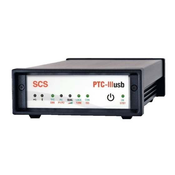
Page 38: Led's
LED to show Bluetooth activity. USB LED: It indicates traffic on the USB port by flashing red for data the PTC-IIIusb sends to the PC and green for date the PTC-IIIusb receives from the PC. - Page 39 ±10 Hz. In Connected State (PACTOR): Tune flashes red while the PTC-IIIusb is in progress with automatic frequency and phase correction. Lock is lit green when the tune process is successfully terminated, the frequency deviation is compensated and the phase is stable.
-
Page 40: Ptc-Firmware
Chapter 5 5 PTC-Firmware With the PTC-IIIusb it is nearly possible to configure everything. In the manual always the default settings are assumed! If you have changed these settings you must keep this in mind while reading the manual. This is very important in case of the control characters which can be freely defined (CHANGEOVER character in chapter 6.19... -
Page 41: Command Structure
The short form of the SERBaud command is SERB. Menus The PTC-IIIusb commands are combined into different function groups, so called menus. The different menus are the following: • Packet-Radio • Audio functions •... -
Page 42: Simultaneous Stby Mode
For that, in the command description you will often find relations to the serial connection interface of the PTC-IIIusb. In this case not a physical serial link is meant, but the virtual COM port created by the USB driver on your PC. -
Page 43: Remote Commands
Packet-Radio. Only a Connect will be rejected in this case. Although the PTC-IIIusb is limited for being a single port unit, it is very flexible also when operating in Hostmode. Same as in the terminal mode it automatically selects the appropriate modem DSP code, dependent on the connect attempt entered by the user. -
Page 44: Ptc-Mailbox
PTC truncates all over long filenames after 10 characters, no difference being made between upper and lower case letters. Entering the Help command via PACTOR the mailbox of the PTC-IIIusb displays a list of available commands. At Read and Send commands (on the terminal side) without a file number, either the first file will be read, or, if more than one file is present, the directory will be shown. -
Page 45: Multiple File Operations
5 PTC-Firmware A list of the commands follows: Command Short description Reference Help !! Chapter 6.44 Help Call the Sysop. Chapter 6.11 BEll Read the main directory OF THE Chapter 6.36 MAILBOX. Gives a list of files within a directory. Chapter 6.48 List... -
Page 46: The Ptc Mailbox For Packet-Radio
It is also possible to use it in smaller general mailbox systems as a stand-alone solution. The PR mailbox in the PTC-IIIusb can be viewed as a self contained TNC in the PTC. This virtual mailbox TNC contains its own callsign, the BBS-MYCALL. The user can reach the PR mailbox in the PTC-IIIusb by connecting to the BBS-MYCALL of the PTC- IIIusb. -
Page 47: Passing Pr Connects To The Mailbox
The USers command in the pac:-menu allows any incoming PR connect to be passes over to the PTC-IIIusb PR-mailbox. To do this USers has to be set to 0. This will allow for example, that on leaving the terminal program, (e.g. automatic de initialising with Y0 in GP) the PTC-IIIusb can be brought to a condition where a connect using the normal MYCALL (i.e. -
Page 48: The Navtex-Processor
CHeck- outputs by being marked with an X (AX.25), e.g: ..NX DL2FAK ... The mail LED starts to blink when a file is written via PR whose filename is the same as the MYCALL of the PTC-IIIusb for channel 0. Read Even during a file read operation, it is possible to give further commands to the PTC mailbox. -
Page 49: The Navtex System In Detail
A NAVTEX controller should therefore be able to operate without any additional computer, and use little electrical energy itself. The NAVTEX processor of the PTC-IIIusb solves many of the disadvantages mentioned above. It enables: • Automatic, selective reading of NAVTEX transmissions. Either the code for the type of message or the regional code can be selected. -
Page 50: Operating The Navtex Processor
PTC-IIIusb multitasking environment. When activated, the NAVTEX processor lays down a directory with the name NAVTEX in the PTC-IIIusb mailbox, and stores all incoming NAVTEX messages there. The name of the message author is given as "AUTO-NAV". The NAVTEX processor gives the complete four figure message header as well as the plain language name of the type of message. -
Page 51: Amtex
5.9.1 Connecting the GPS receiver The PTC-IIIusb uses a 3-pole screw terminator to connect to a GPS reciever. This input is compatible with 5V-TTL and RS232/V24 signal levels. This pins are assignes as follows: Figure 5.1: GPS connector The PTC-IIIusb expects GPS data with 4800 baud and in NMEA format. -
Page 52: Gps Position Request
5.9.2 GPS position request As soon as a GPS receiver is connected, the PTC-IIIusb evaluates the incoming data and saves the actual position with the corresponding (GPS) time. The PTC-IIIusb accepts messages in formats GPRMC, GPGLL, IIRMC and IIGLL. RMC has priority over GLL. -
Page 53: Pactor Duplex And Pactor Data Transparency
“statics” will destroy a many seconds long packet. Just one missing bit leads to a repeat of the whole transmission. To overcome this problem SCS has developed a new class of robust modulation types especially for Packet-Radio. As a special feature for all the variants of this “Robust-PR” a completely new synchronization algorithm with tracking properties that were not possible before has been realized. -
Page 54: Application For Pactor Duplex
The PACTOR duplex is activated with the new command PDuplex (refer to chapter 6.69, page 75). The automatism works with the following relatively simple algorithm: 1. If the PTC-IIIusb is the information sending station ( ISS), that means controls the keys, the PTC-IIIusb automatically executes a CHANGEOVER, if his transmission buffer is empty (that means no data to be sent are available). -
Page 55: How To Avoid Incompatibility
Using the WA8DED hostmode the PTC-IIIusb sends and receives data in PACTOR absolutely binary data transparent. Data transparency is only achieved if both sides use the PTC-IIIusb with the firmware version 2.4 and higher. The data transparency certainly includes all characters being attached to special functions in the terminal mode. -
Page 56: Audio Functions
PACTOR operation. On this reserved channel a connect or disconnect command of the hostmode program is effective on the short wave port of the PTC-IIIusb and establishes a PACTOR connection or terminates it. If the PACTOR listen mode is activated, incoming text will also be displayed in this channel and not in the monitor- screen of the hostmode program. - Page 57 Another comfortable way to initiate a CHANGEOVER in the hostmode is to use the command HCr (refer to chapter 6.43, page 63). If HCr is 1 the PTC-IIIusb executes a CHANGEOVER for each line feed at a blank line. That’s convenient for direct QSOs.
-
Page 58: Commands
6 Commands Chapter 6 6 Commands ACheck (AMTOR Check) Default setting: 30 Parameter: X 0... 100, SNR for AMTOR Packets. This command allows a much sharper error checking than is possible with previous AMTOR systems. By using the analogue information from the A/D converter, it is possible to estimate the Signal/Noise ratio of the AMTOR blocks or the AMTOR CS signals. -
Page 59: Apower
It is naturally still possible to receive PACTOR connects, to read PACTOR QSO's, AMTOR FEC and NAVTEX transmissions. With the SCS-PTC-IIIusb it is possible to use upper and lower case letters in AMTOR! The PTC uses the PLX-APLINK convention to transfer data. It is thus completely APLINK compatible, and can read messages from, and send messages to the APLINK system using both capitals and lower case. -
Page 60: Aqrg
6 Commands If AP is set to 200, the PTC-IIIusb will never set the PSK output level below 200 mV. That means that with a PSKA value of 140 (setting of the maximum PSK amplitude value, refer to the PSKAmpl command, chapter 6.72, page 76) and an AP of 200 the power never will be reduced. -
Page 61: Audio
Bandwith, Center, CWfilter, DD, Delay, Help, Invert, Level, Notch, Peak, Quit, Through, TOne. The usual commands of the PTC-IIIusb are no longer available for use. You can leave the aud:-menu with the Quit or DD command. For a detailed description of the audio commands refer to chapter 7, page 97. -
Page 62: Baudot
6 Commands FFFF<CR> ; Last sector starts with FFFF and is empty AB3C<CR> ; 16 bit checksum on all nibbles Before each block the relevant block number is given. (Incrementing, starting with 0.) The sign > is placed at the beginning of the block number. The block number count enables external software for example, to perhaps recognize any block loss that may occur during data transfer, and in such an event, to undertake damage limitation measures. -
Page 63: Bell
BEll Remote Default setting: 1 Parameter: SYSOP calling disabled. SYSOP calling enabled. This command has no function within the PTC-IIIusb and is just implemented to achieve extensive compatibility with existing PC software 6.12 BKchr Default setting: 25 (Ctrl-Y) Parameter: 1... 127, ASCII code of the character (decimal). -
Page 64: Boot
At Box 2 and Box 3 settings only messages to the own callsign (MYCALL) will be accepted. 6.16 BRightn Default setting: 6 Parameter: 1... 7, brightness value. This command has no function within the PTC-IIIusb and is just implemented to achieve extensive compatibility with existing PC software... -
Page 65: Check
6 Commands 6.17 CHeck Remote (from the remote side entering C is enough, see also Connect, chapter 6.22, page 53) Default setting: 10 Parameter: 1... 100, number of mails to be listed. List private mail only. CHeck without argument lists the newest 10 public mails of the mailbox. With a numerical argument between 1 and 100 it is possible to define the quantity of mails to be listed. -
Page 66: Clr
6 Commands Using <Ctrl-Z> (entering <Ctrl> <Z>) as a CHANGEOVER characters is defined with the command CHO 26. Illegal values are 13 (CR), 32 (Space), 30 (IDLE), 17 (XON), 19 (XOFF), and other previously defined special characters. 6.20 Remote Deletes the transmit buffer. Everything that is contained in the transmit buffer, which has not yet been transmitted, is deleted. -
Page 67: Robust-Connect
TRX remote control option of the PTC-IIIusb, utilizing the socket for remote control of the PTC- IIIusb. The remote control parameter have to be set correctly using the TYpe command of the trx:-menu. -
Page 68: Csdelay
6 Commands CONType defines which connect types the PTC-IIIusb accepts while in standby mode and with this leads to a connection to be established. 6.24 CSDelay Remote Default setting: 5 1... 31, delay in X • 5 msec. Parameter: X Selection of time delay between the end of the RX packet, and start of the first CS data bit. -
Page 69: Cwid
6 Commands If the Ctrl character is immediately followed by a-z (or A-Z), the PTC will transmit a control code (ASCII 1-26) via HF channel. With this simple convention, control characters that are used by your own terminal can also be sent to the other station. If Ctrl-W should be transmitted to the other station, the following keys have to be entered:<Ctrl>... -
Page 70: Cwmoni
Parameter: CW monitor tone disabled. CW monitor tone enabled (TX). CW monitor tone enabled (RX /TX). This command has no function within the PTC-IIIusb and is just implemented to achieve extensive compatibility with existing PC software 6.29 CWSpeed Default setting: 160 Parameter: 40... - Page 71 6 seconds. This has the advantage that user may continue writing after the buffered text is sent, without having to press any other key. The renewed blocking of the transmitted is shown by the PTC-IIIusb with the message '>>>' written to the Delayed Echo-window.
-
Page 72: Cwweight
Faulty inputs cause incorrect settings! From 01.01.1990 up to 31.12.2089, the day of the week is automatically calculated from the date. Thus your PTC-IIIusb is well equipped for the future. Required date Sunday 24th March 2005. -
Page 73: Delete
6 Commands 6.34 This command causes an immediate breaking off of the transmission ('Dirty Disconnect'). An existing link is not correctly terminated. Any text that remains in the transmit buffer is discarded. DD leads, in all cases, back to the respective STBY level.. 6.35 DELete Remote... -
Page 74: Equalize
When the PTC is in the converse mode (ARQ, FEC, CW terminal or RTTY) an ESCAPE character is required in order to get a command prompt and input a command. Note: To ensure proper operation of the PTC-IIIusb´s automatic baudrate detection only odd values for the ESCAPE character should be used)! We recommend not to experiment needlessly with this character, since it is criticial to the control of the PTC. -
Page 75: Fax
30... 3000, AF output voltage (peak to peak) in mV. This serves to set the Audio output (transmitted signal) of the PTC-IIIusb for all non PSK modes. Before this value is changed, the PSK amplitude should have been correctly set (see PSKAmpl command, chapter 6.70, page 75). -
Page 76: Hcr
6 Commands the command mode before each change) adjust the audio output level of the PTC-IIIusb until the required output power is reached (e.g. <ESC> FSKA 100 <Return>). It should be noted that the ALC level of the transceiver must not exceed the prescribed level (exactly as with PSK). -
Page 77: License
Default setting: none The License command does not accept any argument, as PACTOR-3 is always enabled by default with the PTC-IIIusb. If License is sent to the unit, it always responds with a dummy string just like: LICENSE: 010000141714CB53 ABCDEFGHIJKL With this, the PTC-IIIusb always appears as PACTOR-3 licensed to any accessing application software on the PC. -
Page 78: Listen
6 Commands 6.49 Listen Default setting: 1 Parameter: Listen mode disabled. Listen mode enabled. 2..4 reserved Listen PACTOR-1 only The Listen mode is turned on with Listen 1, so that it is possible to 'Listen-in' to what is being sent in PACTOR QSO and to read Unproto transmissions. Listen is only possible in the STBY condition. -
Page 79: Pactor-3
6 Commands CHeck, CLR, Connect, Disconnect, DD, DELete, DIR, HElp, LIst, Listen, LOCk, LOG, Qrt, Read, RESEt, Send, SHow, Unproto, Version, Write. 6.51 Remote This command reads the PTC log entries. The last 16 PACTOR/AMTOR contacts are displayed (except Unproto contacts). The Log entries can be erased with a RESTart (a total reset) or at power-off. -
Page 80: Mark
Parameter: 300... 2700, frequency in Hz. Allows the adjustment of the mark frequency of the PTC-IIIusb in 1 Hertz steps (internal resolution 0.25 Hz, using DDS). The frequency chosen with the MARk command is only used when the TOnes parameter is set to 2 (refer to TOnes command, chapter 6.94, page 87). -
Page 81: Maxsum
6 Commands In AMTOR, the timeout is automatically doubled, so that with the default setting (70), a total of 140 packets (63 seconds) will be transmitted, until the system times out and completely breaks the link. The re-phase timeout for AMTOR is fixed to 32 packets. The value 255 disables the timeout and causes endless traffic. -
Page 82: Monitor
Level II compression turned on, even when transmitting 7Plus, binary files or graphics. No manual intervention by the operator is required, as the PTC-IIIusb will switch automatically to uncompressed ASCII transmission for individual packets, if necessary. -
Page 83: Mycall
Default setting: 3 Parameter: The PTC-IIIusb behaves as a Level 1 controller. The PTC-IIIusb behaves as a Level 2 controller, and will switch to PACTOR-2 when the other station is so fitted. The PTC-IIIusb behaves as a Level 3 controller, and will switch to PACTOR-3 when the other station is so fitted. -
Page 84: Myselc
HELP NAVTEX <Return> If the command NAVtex is given without argument, the PTC-IIIusb displays the present configuration of the NAVTEX processor. The two most essential things to be set up are: •... -
Page 85: Setting The Types Of Messages Required
6.65.4 Choosing the message latency time A somewhat advanced setting possibility allows the PTC-IIIusb to decide after what time period the message is no longer valid. This command is the argument "DAYS" which may follow the NAVtex command. It can contain a number between 0 and 365. This sets the... -
Page 86: Amtex
There now exists an additional parameter "AMTEx". By using this parameter, one can switch between normal NAVTEX operation (AMTEx 0) and AMTEX configuration (AMTEx 1). The default AMTEx parameter is 0. The PTC-IIIusb is thus preconfigured for normal NAVTEX operation. -
Page 87: Null
(refer to chapter 9, page 117). The PACket command can also have a single command from the pac:-menu as argument. As with the other sub menus of the PTC-IIIusb, it is also possible to pass through direct commands this way. -
Page 88: Pduplex
6.71 POSition Remote Default setting: none Parameter: NMEA Requests NMEA raw-data. When a GPS receiver is connected to the PTC-IIIusb, its possible to readout the actual position using the POSition- command. The position information normally has the following format:... -
Page 89: Pskampl
(Please pay particular attention that the chosen frequency is really free. PTC-IIIusb links operate even when the signals are so weak as to be virtually 'non existent'!). Use U 3 <Return>to start the Unproto mode 3 (100 Bd DBPSK). -
Page 90: Remote
AF output level of the PTC-IIIusb is 330 ohm and real. 6.73 PSKTerm Starts the PSK31 operation of the PTC-IIIusb. For further information refer to chapter 11, page 157. 6.74 Returns to PACTOR from the AMTOR, RTTY, PSK31 or CW modes. Activates the PACTOR input prompt (cmd:). -
Page 91: Qrtchr
6 Commands 6.77 QRTChr Default setting: 4 (Ctrl-D) Parameter: 1... 127, ASCII-Code (decimal). Sets the QRT character, which causes the system to go QRT (close the link). It can also be sent is the RX mode, which then becomes active at the next TX phase. In PSK31, RTTY, FEC and UNPROTO it switches from transmit to receive. -
Page 92: Remote
TRX <TRX command> at BOX=1 or //TRX <TRX command> at BOX=0 is available. The user has the chance to receive the frequency list of the PTC-IIIusb, including the capability of changing the transmit frequency or modifying the channel list (e.g. -
Page 93: Rle
Default setting: auto Parameter: baudrate auto The USB driver of the PTC-IIIusb is pre-set to the given baud rate of 115200 baud. Baud rate settings in PC programs do not care. 6.86 SFile The SFile command (send file) works exactly as the Send command, except that the additional information (file header, EOF text, Path text) is not suppressed. -
Page 94: Space
Parameter: 300... 2700, frequency in Hz. Allows the adjustment of the space frequency of the PTC-IIIusb in 1 Hertz steps (internal resolution 0.25 Hz, using DDS). The frequency chosen is only used when the TOnes parameter is set to 2. (refer to chapter 6.95, page 88). -
Page 95: Status
The ZCZC/NNNN autostart can be activated setting the squelch parameter to a value between 100 and 200. If the squelch value is set to 140, the PTC-IIIusb operates with the ZCZC/NNNN autostart and additionally with the normal analog squelch of 40 (value minus 100). -
Page 96: Table 6.3: Ptc Status Information, Bit 0-2
During the transmission of status information new status requests are ignored. In status mode 2, the PTC-IIIusb has an automatic status output. This means that the status no longer needs to be regularly polled by the terminal program. Instead, every status change causes the status information automatically to be given. -
Page 97: Systest
RF channel busy. Table 6.4: PTC status information, Bit 4-6 In STBY condition the PTC-IIIusb analyzes the HF channel and differs between busy and free.A busy channel is defined as all signals that are audibly distinctly different from noise, but, however, having a speed < 250 Baud. Packet-Radio (300 Baud) is virtually ignored. -
Page 98: Term
Split screen with command prompt recognition. Split screen also for Packet-Radio. With this command it is possible to make the PTC-IIIusb support split screen terminals. In simple terminal mode text is not sent to the terminal when the PTC receives commands from the user. -
Page 99: Table 6.5: Code Byte Description
6 Commands present transmit channel in terminal mode. This means that one must set Setch to 2 if one wishes to transmit data via channel 2. (If for instance an external link from the PTC- IIIusb has been automatically given channel 2 and one wanted to write a text to that other station.) Terminal programs that fully support Term 5 must therefore also automatically administrate the Setch command. -
Page 100: Time
Without a workaround this programs could not be used with the PTC- IIIusb. This workaround is represented by the TNC command. Using this command, the PTC-IIIusb, up to the desired extend, adapts its behavior to react similar to the WA8DED command interpreter. The PTC-IIIusb reacts similar to a normal TNC if the TNC command is activated. -
Page 101: Tones
PTC-IIIusb can always be operated with the TNC set to 1. 6. The PTC-IIIusb shows the same behavior as in the TNC 1 mode, but additionally the prompt will be altered to asterisk *, i.e., the PTC answers to a ESC character not with the cmd:-prompt but with the asterisk. - Page 102 6 Commands PACTOR-I/II connections. Furthermore we recommend to work PACTOR-3 only on the upper sideband (USB). Please also note that the audio passband, i.e. the occupied audio spectrum, of the PACTOR-3 signal always is fixed at 400-2600 Hz and INDEPENDENT of the TOnes setting.
-
Page 103: Trx
6 Commands Only valid for RTTY and AMTOR. Inverts the TX and RX audio shift (mark and space tones). 6.97 Remote The TRX -command (without argument) activates the transceiver remote control menu (trx:-menu). The command prompt takes the form trx:. The following transceiver control commands are allowed within the trx:-menu: Channel, Down,... -
Page 104: Unproto
6 Commands Unfortunately, within the ranks of PTC clones, there is equipment that cannot convert the umlaut (multimode controllers from the USA). In order to remain compatible with these systems, the PTC allows the umlaut coding table to be turned off. 6.100 Unproto Default setting: 1*2... -
Page 105: Update
If no argument is given, then the PTC-IIIusb uses the mode that was last used, or the default setting. The actual mode is shown on the LED status field. The Unproto mode may be terminated with a QRT character, a Disconnect. It is always possible to abort a unproto transmission using the command DD. -
Page 106: Remote
PTC-IIIusb - High Performance HF/VHF/UHF Communications Controller PACTOR - Level-III - High Speed Data Transfer Protocol >>> Professional / Marine Firmware V.4.1 <<< (C) 1994-2012 SCS GmbH & Co. KG - Germany BIOS: Version 2.12 detected Packet Radio Port: SCS - DSP MULTI MODEM detected Parameter # with the version-command (terminal-mode) displays the most important modem properties in a special format. -
Page 107: Write
3. and 4. digit as 1. and 2. digit, but for port 2. (Also with single port devices all 4 digits are always displayed.) #5: (PACTOR-3-License) N = no permanent license installed V = permanent license installed (default for the PTC-IIIusb) 6.106 Write Remote... -
Page 108: Xuser
The XUser command is used to manage the user list. The PTC-IIIusb firmware allows to define user specific access priorities, i.e., that it is possible to define in a user list if for example the user DK9FAT is permitted to use the PR PACTOR gateway or if he is allowed to read private messages for other callsigns from the Packet side, etc. - Page 109 Sets the priority for the callsign CALLSIGN to the value xxxx. The numbers 0-9 are allowed for each character within xxxx, e.g. 1330. No spaces between the numbers are allowed. If less than 4 digits are defined, the PTC-IIIusb automatically adds a 0 at the missing positions. The PTC-IIIusb confirms with “OK”.
-
Page 110: Audio
CWTerm, chapter 6.30). The Center command also adjusts the audio frequency of the CW-Terminal (chapter 6.30) of the PTC-IIIusb send and receive sides. (In firmware releases prior to version 1.12, the CW-Terminal used the current Mark-frequency, which sometimes was not particularly suitable). -
Page 111: Delay
7 Audio Terminates the aud:-menu. Delay Default setting: 100 Parameter: 0... 1500, delay in ms. Defines the delay time between the Audio-IN (socket X5, PIN 4) and Audio-OUT (socket X5, PIN 1) signal. Help Lists all commands used in the aud:-menu. Invert Default setting: 3000 Parameter:... -
Page 112: Through
7 Audio 7.11 Through Loops through the Audio signal direct, i.e. without filtering, from the input (ADC) to the output (DAC). 7.12 TOne Default setting: 1000 Parameter: 1... 4000, frequency in Hz. 1... 4000, frequency in Hz. Starts the sine wave generator. The frequency required is given as an argument for the command. -
Page 113: Fax
Chapter 8 8 FAX General Information In addition to the normal teletype modes the PTC-IIIusb supports the following modes; FM-FAX (Shortwave), AM-FAX (Satellites), SSTV (All present standards) and NFSK- Demodulation for decoding various shortwave teleprinting methods. The algorithms used here, profit from the relatively high computing power of the PTC- IIIusb and allow the system to easily reach the theoretical limits regarding definition, filter performance and resistance to interference in all picture operating modes. -
Page 114: Fm-Fax
The pixel-rate from Meteosat 5 is 3360 pixels per second - 4 lines are transmitted per second. The resulting bandwidth (relating to the appropriate Nyquist filtering) is ± 1680 Hz or a total of 3360 Hz. The PTC-IIIusb allows the maximum possible resolution of the Meteosat signal to be displayed. -
Page 115: Sstv
8 FAX information is maintained. (If the wrong sideband is chosen then the pictures are inverted, i.e. black lines are drawn white and vice-versa). 8.2.3 SSTV With use of a computer creeping into virtually every shack, the SSTV mode has changed from a technical challenge for a few specialists, to a relatively wide-spread and amusing amateur radio pastime. -
Page 116: Fax And Sstv With Jvcomm32
PTC-IIIusb has the same behavior as the previous FMfax modem (also activated within the fax:-menu). The only difference is that the PTC provides no receiving data while the JVComm modem of the PTC-IIIusb is in transmission state. That means that no full- duplex with loop back is possible. -
Page 117: Reference Of Databytes Concerning The Ptc
8 FAX 8.3.2 Reference of databytes concerning the PTC Value Reference 0-240 Normal, linear frequency transmission data 0 = 1500 Hz 24 = 2300 Hz Sync tone 1100 Hz Sync tone 1200 Hz Sync tone 1300 Hz The values 0-243 trigger the PTT and the transmission mode of the JVComm modem. As soon as one of these bytes is received, the PTC usually switches to transmit and keeps this condition for (2500 * 1/data rate) seconds (re-triggerable). -
Page 118: The Ptc-Iiiusb As Comparator-Modem
Modem command, refer to the MBaud-Parameter command. The MODEM operation of the PTC-IIIusb can be ended at any time by inputting a byte with the value 255 (dec). via the RS-232 port. It is essential to use the correct baud rate (see MBaud-command!). -
Page 119: Modem Commands In Detail
0 to 255. Measured values greater than 255 are limited to 255 by the PTC-IIIusb. (The data width is limited to 8 bits by the serial format.) With an AF input amplitude of 500 mV, and a standard setting of AGain (50), the PTC-IIIusb gives an output value of 255. -
Page 120: Jvfax
(SMode), with the help of which the PTC-IIIusb is informed of the current SSTV sub-mode being used. The multi-line check may be turned off, which... -
Page 121: Jvcomm
DSR signal in the USB data stream. It has passed a trigger stage, which results in a 1-bit digitized signal as output. If the PTC-IIIusb measures an input frequency of greater than 1900 Hz, the virtual DSR goes active. For frequencies lower than 1900 Hz, the PTC- IIIusb sets the virtual DSR to inactive. -
Page 122: Comparator
166.7 ms (for example when in FM-FAX only white must be transmitted), then the PC program must send data to the PTC-IIIusb at least every 166.7 ms, so that the transmitter stays on transmit. By using this system, an extra PTT-command is not required. -
Page 123: Transmission In Am-Fax-Modem Mode
The transmitted data controls the instantaneous frequency of the output signal. For the value 0, the PTC-IIIusb generates a frequency of 1500 Hz. The value 63 produces a frequency of 2300 Hz. Values between these limits produce the appropriate frequencies between 1500 and 2300 Hz. -
Page 124: The Parameter Commands In Detail
8 FAX The Parameter commands in detail 8.8.1 AGain Default setting: 50 Parameter: 1... 200, amplification factor for AM-FAX. Sets the internal amplification factor for AM-FAX reception. The brilliance of the received picture can thus be set, without having to change the receiver volume. Some receivers offer an AF-output with a virtually constant amplitude. -
Page 125: Sresolut
8 FAX 8.8.4 SResolut Default setting: 2 Parameter: 1000 Pixel/sec. 1500 Pixel/sec. 2000 Pixel/sec. 2800 Pixel/sec. Gives the maximum possible time resolution of the received signal in SSTV. Also the SResolut parameter adjusts the bandwidth of the input bandpass-filter appropriately. With noisy signals, it is recommended that the SResolut parameter is set to 0, as the effective signal to noise ratio is thereby increased. -
Page 126: Hsynch
JVFAX convention, into the two lowest bits of each of the data- bytes given out on the serial interface. If there is no synch-pulse present, then the two lowest bits (0 and 1) are set to 1. The PTC-IIIusb erases the two lower bits for the period of a synch-pulse. -
Page 127: Txcomp
HAMCOMM-modem to send FAX and SSTV direct from the PTC-IIIusb. The PTC-IIIusb looks at the voltage appearing on the CTS-line of the serial interface. When CTS is active, the PTT line for the shortwave port is activated. The PTT line is de- activated (turned off) with inactive CTS. -
Page 128: Tips And Tricks
8 FAX 8.10 Tips and Tricks 8.10.1 IF-SHIFT With the normal SSB speech reception, the speech frequencies stretch from 300 to 2700 Hz. Steep sided SSB filters usually have a 6 dB bandwidth of around 2.4 kHz. The FM- FAX standard sets a center frequency of 1900 Hz. With standard resolution FAX and SSTV pictures, the signal requires a bandwidth of approximately 2.5 kHz. -
Page 129: Packet-Radio
The PACket command can be followed by a valid pac:-command as an argument. As with the other sub functions of the PTC-IIIusb, it is also possible to pass through direct commands. Switch off the Packet-Radio listen – without using the pac:-menu cmd: PAC M 0 <Return>... -
Page 130: Robust Hf-Packet
9 Packet-Radio The most frequently done mistakes according to wrong times are: • At connect establishment all attempts of the PTC-IIIusb are transmitted in very short distances. • On a DAMA-Digi it could happen that suddenly the connection hangs. Digi and PTC- IIIusb exchange RR frames only. -
Page 131: Baud Hf-Packet
9 Packet-Radio a few users are present but the distances are large then the longer but more robust modulated packets can be used. In the opposite case, when many participants are present but the average distances are smaller, then the faster/shorter packets can be used. 300 Baud HF-Packet HF-Packet is activated with the command Baud. -
Page 132: Activating Kiss-Mode, The Commands Kiss And @K120
9 Packet-Radio Because of this, KISS is not suitable for e.g. PACTOR: The timing-critical PACTOR protocol cannot easily be implemented on a PC with multitasking operating system and transported via a KISS interface to the modem. Via KISS only Packet-Radio modems can be accessed. -
Page 133: Commands
Sets the comment text that is added to every APRS-datagram. E.g. a short description of the system can be entered: “PTC-IIIusb 20 W, Dipole”. The comments maximum length is 40 characters. Longer comments will be rejected with an error message. A minus character (-) as first Comment character sets the Comment to “NONE”, and with this... - Page 134 However because some APRS programs cannot correctly interpret the compressed format, the SCS firmware allows the compression to be switched off. Also the uncompressed position data can be directly monitored as the usual...
- Page 135 9 Packet-Radio 9.8.1.5 APRS SYmbol Default setting: 15 [Dot] Parameter: 1…94, a1…a94 Sets the graphic APRS symbol that an APRS receiving station should display: e.g. a symbolic car in mobile service (Symbol 30). The symbol numbers follow exactly the table in the APRS protocol version 1.0. The complete protocol information is available on the Internet.
-
Page 136: Baud
Connect bell off. Connect bell on. Turns the connect bell on, or off. If the connect bell is turned on, then every connect is signaled with the PTC-IIIusb sending a bell character (<BEL>, ASCII 7) to the terminal. 9.8.4 CHeck... -
Page 137: Connect
Activates the display of time stamps on connect and disconnect messages. 9.8.8 CONVerse Manually activates the converse mode. This function is seldom needed, as the PTC-IIIusb automatically switches to the converse mode after a successful link up. Alternatively a K may be used, as abbreviation for CONVerse. -
Page 138: Digipeat
Parameter: 1... 15,000, time in milliseconds. FRack sets the time in which a packet must be acknowledged. If the PTC-IIIusb sends a packet, and no acknowledgment is forthcoming within the Frack time, then the PTC- IIIusb queries if the information has arrived. -
Page 139: Jhost
The command is used by the hostmode software to switch to the hostmode. During normal operation within the terminal mode this command has no function. For furthermore information about the PTC-IIIusb hostmode refer to chapter 10, page 135. It is strictly forbidden to enter the JHOST command in the initialization file of the hostmode programs! hostmode programs switch to the hostmode independently. -
Page 140: Mfilter
9 Packet-Radio 3 - Additionally SABM- and DISC-Frames. 4 - Additionally UA- or DM-Frames 5 - Additionally RNR, RJ and FRMR 6 - Additionally Poll/Final Bit, PID and serial numbers 9.8.19 MFIlter Default setting: 10 Parameter: 1... 128, max. 4 ASCII characters. This command removes the given characters from the data stream (maximum 4 arguments). -
Page 141: Mtext
MYAlias is handled as MYcall for incoming connects, and can also be used as an alternative station callsign. If the PTC-IIIusb is called by the MYAlias callsign as a digipeater, he works as a cross port digipeater, i.e., packets received at port 1 are send out at port 2 and vice versa. The kind of modem at the relevant port is not important, because of this cross digipeating from 1200 baud to 9600 baud and vice versa is possible. -
Page 142: Mycall
For each channel an own callsign can be defined temporarily. After a disconnect the callsign will always be taken from channel 0 again. After switching on the PTC-IIIusb the firmware checks if a valid callsign is written in the PACTOR-MYCALL. In this case (i.e. no *SCSPTC* defined as PACTOR-MYCALL), the PTC-IIIusb copies the PACTOR-MYCALL to all PR channels which are still having SCSPTC as MYCALL, and overwrite the SCSPTC with the valid mycall. -
Page 143: Prbox
1... 30,000, response time delay Sets the value for the AX.25 timer-2 (T2) in milliseconds. After receiving a packet the PTC-IIIusb waits the time T2 to check if another packets follow. If so, all packets can be confirmed with only one control packet. -
Page 144: Slottime
9 Packet-Radio The PTC-IIIusb provides 32 logical channels to the user, numbered from 0 to 31. The Setchn command defines the channel to be written on. A special status has the channel 0. Channel 0 is the channel to transmit not protocolled messages, as CQ calls or beacon. -
Page 145: Txlevel
To start an Unproto transmission, just enter the Converse mode with K, and, everything that is then typed, and ends with <Return> is transmitted by the PTC-IIIusb. <Esc> returns the pac:-prompt, the entry of K then ending the Converse mode. - Page 146 -8) will be transferred to the mailbox. This is useful, as many potential users would use the normal MYCALL to connect to the PTC-IIIusb. If the terminal is off-line, and the configuration is correct, (USers 0 or Y0) then all calls, irrespective of if they are the normal MYCALL, the MYALIAS, or the BBS-MYCALL, will be transferred to the PTC-mailbox.
-
Page 147: 10 Hostmode
The hostmode implemented in the PTC-IIIusb is largely compatible to the WA8DED hostmode, as found in virtually all TNC´s, but is only used when the PTC-IIIusb is connected to a computer, and controlled by a special hostmode program (e.g. GP, SP, WinGT, WinPR, TNT, etc.). -
Page 148: Modern Times
PR PORT: SCS – DSP MULTI MODEM at 1200 baud. Display 10.1.1: hostmode Start message If you want to control the PTC-IIIusb directly after starting with a hostmode program, the baud rate should be set with the SERBaud command to a fixed value (refer to chapter 6.85, page 80). -
Page 149: Dama
The expression [DAMA] is added to the header of the monitored packets, if the packet is received by a DAMA-Digi. The DAMA mode needs not be activated by the user. The PTC-IIIusb automatically notices if you are working with a DAMA-Digi or not and behaves respectively. -
Page 150: Jhost
1… 15,000, time in milliseconds Frack-Timer (T1). Frack sets the time in which a packet must be acknowledged. If the PTC-IIIusb sends a packet, and no acknowledgment is forthcoming within the Frack time, the PTC-IIIusb then queries whether the information has arrived. - Page 151 M sets which frame types will be displayed in the monitor. 10.4.10 N Default setting: 10 Parameter: 0… 255, number of repeats. Sets the maximum number of repeats, and if this value is exceeded, then the PTC-IIIusb gives out the message: LINK FAILURE with <call> 10.4.11 O Default setting: 7 Parameter: 1…...
- Page 152 Enable or disable the connect text. U defines the connect text. U 1 Here is the PTC-IIIusb – The PTC-IIIusb switches on the connect text and the text will be “Here is the PTC-IIIusb ”. U 1 – asks for the connect text...
- Page 153 5 stations, and a further station attempts to connect, this connect request will be refused. The Y command allows any incoming PR-connect to be transferred to the PTC-IIIusb PR- mailbox, but only if Y has to be set to 0. This will allow for example, that on exiting the terminal program, (e.g.
- Page 154 10 Hostmode This command is only used by the hostmode program. The user cannot enter this command. 10.4.22 @F The hostmode command @F allows to setup FAX reception under hostmode control. Receveiving FAX images through the hostmode interface means that the data transfer between modem and PC is highly buffered and error-corrected (CRC hostmode).
- Page 155 1... 30,000, response time delay Sets the value for the AX.25 timer 2 (T2) in milliseconds. After receiving a packet the PTC-IIIusb waits the time T2 to check if another packets follow. If so, all packets can be confirmed with only one control packet.
- Page 156 10 Hostmode The @T3 command sets the T3 or link activity timer. If nothing is received from the distant station for the time T3, then the link status is polled. 10.4.27 %B Default setting: 1200 or 9600 Parameter: Rx Rx baud rate for the radio link. Tx Tx baud rate for the radio link.
- Page 157 Note: Code byte 8 is not defined in WA8DED-hostmode, and is used to define a special extension of the PTC-IIIusb. Terminal programs which wish to work with the delayed echo in hostmode, must logically be appropriately extended to contain this feature, and choose the extension required automatically.
- Page 158 10 Hostmode Format for example: 4.0 2.09 Characters left of the dot are the main version number of the firmware. Characters after the first dot until the first blank character are the sub-firmware version number. Letters may also appear here. At least one blank separates the firmware version number and the BIOS version number.
-
Page 159: Extended Hostmode
10.5 Extended hostmode The PTC-IIIusb supports the so called extended hostmode. The extended WA8DED- hostmode has established itself as a de-facto standard for communication between TNC/PTC and PC-control programs. -
Page 160: Status Output In Hostmode
The usual status byte can be called in the hostmode by polling channel no. 254. A G poll of this channel always outputs a string containing the actual status information of the PTC-IIIusb. The format is: 254,07,0,S. (S = binary status byte). It is hence a byte-count format: channel number, code, length minus one, information byte(s). -
Page 161: Trx Control Channel On Hostmode
GPS receiver. Except the terminating <CR> (ASCII13) the data is exactly matching with the one the GPS receiver sends. The PTC-IIIusb buffers 32 sets of NMEA data internally. This NMEA channel is also included in the extended hostmode channel 255, which means that the usual poll on channel 255 is sufficient to determine if there is new NMEA data available on channel 249. -
Page 162: Extended Crc-Hostmode
10 Hostmode 3. Data transmission via multiple nodes (e.g. WINLINK forwarding) increases the potential for error due to corruption via the RS-232 links. Possible sources of error: • During active transmitter operation, HF can corrupt data. • Short spikes due to heavy loads being switched on or off on the AC power line, or through close lightning strikes etc. -
Page 163: Master Protocol
- When no reaction is received from the SLAVE within 250 ms after the MASTER transmitted packet has ended. - This is a minimum time. The PTC-IIIusb answers within a few milliseconds. With very slow TNCs the waiting time can be changed in the MASTER program. -
Page 164: Slave-Protocol
10 Hostmode Reaction of the MASTER to various conditions • Reaction of the MASTER to an NACK condition. - Repetition (transmit) of the buffered last packet with the request-bit unchanged. • Reaction of the MASTER to an ACK condition. - A new packet can be sent to the slave, if available. The request flag is inverted before the transmission. -
Page 165: Start Of The Crc-Hostmode
10 Hostmode • #170#170 ALWAYS leads to a start of packet condition, under all situations. The next byte is then appropriately interpreted as the channel number. (However after a start of packet is recognized, two #170 in a row must follow so that this exception can work again. -
Page 166: Example Source Code For Ccitt Crc16 (Hdlc)
10 Hostmode 10.9.7 Example source code for CCITT CRC16 (HDLC) Example program in Turbo PASCAL: Program CCITT-CRC; crc_table : ARRAY[0..255] OF Word; (* dynamically built up *) crc : word; Procedure CALC_CRC_CCITT( b : Byte); BEGIN crc := ((crc SHR 8) AND $ff) XOR crc_table[ (crc XOR b) AND $ff]; END;... - Page 167 10 Hostmode included in the CRC have been processed, then first one hangs the low-byte from WORD CRC and lastly the high-byte on the Block as "CRC". With the 5 example bytes calculated above, the LOWBYTE=213 and HIGHBYTE=153. When checking the CRC ("reception") one also calculates both the transferred CRC-bytes into the CRC-value.
-
Page 168: 11 Psk31
After turning on the PSK31 terminal, the PTC-IIIusb is in the receive condition. Various PSK31 relevant settings are at their default or previously set values. The Quit command closes the PSK31 terminal, and returns to the normal STBY condition. -
Page 169: Level Setting
Switching to continuously open (Garbage on the screen, even when no PSK31 signal is present) should only be necessary in exceptional circumstances. The PTC-IIIusb acknowledges the command with “*** SQUELCH: ON” or “*** SQUELCH: OFF”. Default value: Squelch in normal condition (=ON). -
Page 170: Receiver Tuning
Cycles between the operating modes DBPSK, DQPSK and inverted DQPSK. Ctrl-B: If a DQPSK variant is chosen, the PTC-IIIusb signals this with the DQPSK LED. Inverted DQPSK is needed when lower sideband is used on an SSB transceiver, as here the signal phasors revolve anti-clockwise, and thus build up a false delta-phase association for the values 90 and 270 degrees. -
Page 171: Cw-Identification
PSK31 channels are not disturbed during the CWID. The PTC-IIIusb sends an additional CWID after a PSK31 transmission if the CWID-Parameter (refer to CWid, chapter 6.27, page 56) is higher than 0. -
Page 172: 12 Systest
PTC is in the receive condition. This has the great advantage if one has the PTC-IIIusb in use as an AF filter/denoiser: NOTE: With some older or simpler radios, it is possible for feedback to occur when the received signal also appears at the transmitter microphone input. -
Page 173: Fsk
12.7 LED test. The PTC-IIIusb shows off its lighting console. 12.8 Tests the DSP PLL. With correct operation of the PLL, the PTC-IIIusb gives OK. In case of error, NOT OK is given. 12.9 Activates the PTT test routine. The PTT switching transistor is toggled on or off by means of <Return>. -
Page 174: Ram
12 SYStest 12.11 Displays the measured RAM available in the PTC-IIIusb. 12.12 SERNum SERNum displays the serial number of the PTC-IIIusb. This number alwas has 16 digits. SERNum answers as follows: Serial number: 01000005A6E69C22 12.13 Trxtest Tests the transceiver control port. This command is only working properly when using a... -
Page 175: 13 Trx
13 TRX Chapter 13 13 TRX The TRX -command (without argument) activates the transceiver remote control menu (trx:-menu). The command prompt takes the form trx:. The following commands are allowed within the trx:-menu: Channel, DD, Down, DUmp, DWell, Frequency, Help, List, Offset, Ptime, RType, Scan, TImer, Transfer, TYpe, Up, Quit, Wait, Xscan. - Page 176 13 TRX 14075.600 LA2MV 14080.000 9K2EC special 3587.000 SM3HUA QRG 3595.400 DJ9YJ QRG 3588.000 DK0MAV HB9AK 14077.000 second ch dl2fak The Channel command (without argument) behaves exactly as a List command for the TRX command set. All user defined channels are listed. If the Channel command is followed by ONE argument, consisting of a number between 1 and 32, then the PTC switches the connected TRX to the given channel frequency.
-
Page 177: Dump
The header is only then valid when it appears complete. If, for example, the third header byte is defective, then the PTC-IIIusb behaves as if the Ctrl-E start character is an accidental Ctrl-E, or an actual Ctrl-E that has not been input as a TRX control character, the PTC-IIIusb then sending the buffered characters of the intended dump header into the normal command interpreter or transmit buffer. - Page 178 If, however, the Ctrl-E should be defined as a control character, then the PTC-IIIusb will not give an error message, the processing of the Ctrl-E as Hot- key being delayed when the dump mode is active, for a minimum of one character, and the respective following characters are checked, to see if they are valid for the TRX dump header, in other words, a buffering taking place.
-
Page 179: Dwell
Without a parameter the Frequency command returns the current operating frequency from the transceiver. If a beep is heard during frequency input or scanning, that’s not the PTC-IIIusb, that’s the transceiver. Refer to the transceiver manual to switch off the confirmation beep! 13.6... -
Page 180: List (Remotable As Command Trx List)
SSB transceiver to. If the Offset value is defined as 1.4 kHz, the PTC-IIIusb does the required frequency correction for the Mark frequency automatically. It is thus only necessary to give the wanted Mark frequency, and the correct offset is automatically applied. -
Page 181: Ptime
Sets the time (in Milliseconds) for the Up and Down keying pulse, that can be initiated from the Up and Down commands (trx:-menu). A Ptime value of 50 means that the respective switch in the PTC-IIIusb per impulse is closed for 50 ms and open for 50 ms. 13.12 Quit Serves to leave the trx:-menu. -
Page 182: Timer
Leading zeros are also optional. If the TImer command is given without arguments, then the PTC lists the entire timer table. If only the timer number is given as argument, then the PTC-IIIusb shows the times defined for only this timer. -
Page 183: Type
CODAN, ICOM / KENWOOD / NMEA ICOM / R&S / SGC / YAESU Baudrate (1200 – 115200 Bd) ICOM ID / VFO (A/B). V24/TTL Enables the configuration of the PTC-IIIusb TRX interface. There are up to three arguments allowed. The first argument indicates the transceiver, the following transceiver are supported: • CODAN •... -
Page 184: Wait
13 TRX Data from the receiver is not reformatted by the PTC-IIIusb, but simply fed through directly to the terminal. For the Frequency command without argument not the offset corrected frequency in kHz will be displayed, but the original string from the transceiver. -
Page 185: Xscan
Set Scan parameter of channel 4 to YES. trx: XS 4 1 <Return> The XScan command is particularly useful in the initialization/configuration file of the PTC-IIIusb, because a new defined state can be set without knowing the current state of the scan parameter. 13.20... -
Page 186: External Scan Stop Signal
13.21 External Scan Stop Signal The PTC-IIIusb transfers a scan stop signal via the USB interface, which the driver provides as virtual CD signal. The CD signal is active, as long as there is no scan stop condition valid, which means that the external scanner may change the frequency of the radio. -
Page 187: 13.23.1 Preamp Switching At R&S Xk-2000 Transceiver
The P attribute is however very suitable for use with time controlled NAVTEX reception. If the T or P attributes are used for a non-defined TImer number, then the PTC-IIIusb just ignores them. 13.23.3 Hex Attribute We recommend that only experienced PTC users utilize the #:h attribute because improper usage can cause a general malfunction of the transceiver remote control. -
Page 188: 13.23.4 Level Attribute
13 TRX With the aid of the new channel attribute #:h arbitrary binary data can be transferred to the transceiver through the TRX port. For example, a different IF filter bandwidth can be assigned to each scan channel and thus automatically be changed during scanning. Changing the bandwidth is useful when narrow (“PACTOR-2 only”) channels and wideband channels are supported simultaneously. -
Page 189: 14 The Bootloader
Chapter 14 14 The Bootloader Hier The internal operating software of the PTC-IIIusb is divided into two major parts: Firmware: Operating software available to the user, which supports, for example, PACTOR, AMTOR, RTTY, etc, including the command interpreter and multitasking. and for which an update is occasionally available, to provide additional and improve current features. -
Page 190: Activating The Bootloader
14 The Bootloader 14.2 Activating the Bootloader The Bootloader is activated with the “BIOS” labeled switch on the rear side of the unit. If the PTC-IIIusb is in Bootloader mode then only the CON-LED lits. 14.3 Bootloader commands 14.3.1 FCall... -
Page 191: Systest
14.3.5 UPDATE Identical to the UPDATE command in the PACTOR firmware. This command renews the PACTOR firmware in the Flash ROM of the PTC-IIIusb. It should only be used together with the corresponding program on the PC. 14.3.6 Version Displays the version number of the Bootloader. -
Page 192: 15 Basics
AMTOR, have been retained. These result in a protocol much more resistant to interference than Packet-Radio under poor propagation conditions. The PACTOR protocol, together with the SCS-PACTOR Controller, allows a much higher throughput than AMTOR, with the efficient error correction and data transparency of Packet-Radio. -
Page 193: Why Pactor-2
15 Basics operation. The original SCS-PTC uses a real analogue memory ARQ, whereby the received AF tone is not simply turned into 0 or 1 data, but intermediate values are also stored. Therefore a more fine-tuned analysis is possible than with so-called "digital memory ARQ". -
Page 194: Basics Of The Pactor-2 Protocol
15 Basics • Longpath option (ARQ links over the long path possible). • Reliable QRT acknowledgment from both sides (not just a simple time-out). • Fast and reliable change of data direction. • High performance read function without additional software. •... -
Page 195: The Modulation System
15 Basics 15.3.2 The modulation system As with the previous FSK standard, PACTOR-2 also uses two tones (or carriers). These are, however, not just sent alternately to transmit the data, they are both sent together as continuous tones. The data is contained in the phase of each tone, or, to be more exact, in the phase difference between two consecutive information states or steps. -
Page 196: Figure 15.2: Pactor-2 Spectrum And 300 Bd Fsk 200 Hz Shift
15 Basics robustness in noise, and resistance to multipath effects. As the two tones work in parallel, the PT-2 system reaches a total modulation rate of 200/sec. The reason why differential PSK is used on HF links is that signals are much too unstable and noisy (or with too large a frequency error) to be used effectively by "normal"... -
Page 197: Error Control Coding
15 Basics Modulation Scheme Total bit rates (Bit/s) DBPSK DQPSK 8-DPSK 16-DPSK Table 15.1: Total Bit Rate The complex PT-2 modulation scheme is totally different to the simple FSK. Therefore it is IMPOSSIBLE to use the FSK modulators found in some transceivers to generate the signal. - Page 198 15 Basics information plus redundancy) is called the code rate. A very simple code, the (7,4) Hamming code for example has a code rate of 4/7, as for every four useful bits of information, three redundancy bits are added. It can correct exactly one bit error per block of seven bits.
-
Page 199: Online Data Compression
(PMC) as a compression method. PMC has been developed by SCS, and increases the throughput of plain text by a factor of 1.3 compared to Huffman coding. The PTC-IIIusb examines each packet individually to see if it would be faster to send it using Huffman, PMC, or normal ASCII transmission. -
Page 200: Pactor-2 In Practice
(non-adaptive) Markov compression. The SCS team, in developing PT-II, came up with a simple and clever answer to these problems. The Markov compression would be limited to the 16 most common leading characters. -
Page 201: Cq Calls And Broadcasts
NEVER tune the VFO by hand with very weak or inaudible signals! With very weak or noisy signals, the PTC-IIIusb adjusts its tuning very slowly to minimize tuning error. With good, to very good, propagation conditions, PT-2 has shown itself to be 4 to 6 times faster than PACTOR-1. -
Page 202: 16 Accessories
Chapter 16 16 Accessories For the PTC-IIIusb the following accessories are available: For the SCS PTC series the following accessories are available: • Packet-Radio 9k6 cable Direct connection from VHF/UHF-transceivers with DATA-connector (6 pin Mini- DIN) to the PTC (5 pin DIN). - Page 203 TRX-control (13 pin DIN) to ICOM CIV port (3.5 mm pin connector) and 3.5 mm speaker connector. Order-No.: 8170 • USB-Cable Cable to connect the PTC-IIIusb to the PC. Order-No.: 8030 • Bluetooth USB-Stick For computers which do not have Bluetooth on board yet. Is plugged into a free USB connector on the PC.
-
Page 204: 17 Technical Data
A Technical Data Appendix A 17 Technical Data Audio input impedance: 47 kΩ Audio input level: 10 mVp-p... 2Vp-p Audio output impedance: 1 kΩ Audio output level: Max. 3 Vp-p (open circuit), adjustable in 1 mV steps Audio processing: Digital signal processor DSP56303 clocked at 100 MHz 768 kByte additional DSP-RAM for data and program Central processor: Motorola MC68360 QUICC 32 bit CMOS CPU clocked at 25 MHz... -
Page 205: 18 Connector Pin-Out
The PTC can be powered from the two pin screw terminal on the rear panel, according with the printing on the panel. The USB connector The PTC-IIIusb is connected to the computer using a type B USB connector Figure D.1: USB connector Transceiver remote-control socket Pin 1: RxD TTL. - Page 206 B Connector Pin-out The 8 pole DIN socket Pin 1: Audio output from the PTC to the transmitter. Pin 2: Ground. Pin 3: PTT Output. (to transmitter PTT line) Pin 4: Audio input from the receiver to the PTC. (loudspeaker or appropriate AUX socket). Pin 5: Optional power supply input.
- Page 207 B Connector Pin-out Cable Color Code 8-pole DIN Color Color Violet Blue White Yellow Black Green Brown Table D.1: Cable Colors: 8-pole DIN-cable 5-pole DIN Color Violet White Yellow Green Blue Table D.2: Cable Colors: 5-pole DIN-cable 13-pole-DIN Color Color violet white pink...
-
Page 208: 19 Glossary
Glossary Appendix C 19 Glossary Analog Digital Converter AFSK Audio Frequency Shift Keying AMTOR AMateur Teletype Over Radio – ARQ-FAX process developed out of the SITOR process by G3PLX. ANSI American National Standardization Institute. A Terminal-Emulation-Protocol was determined by ANSI, which has been established as a standard for mailbox systems. The ANSI-Terminal Emulation offers cursor control, color support, block graphic and generation of signal tones. - Page 209 Glossary Central Processing Unit. CSMA Carrier Sense Multiple Access (to the transmission channel). A channel access process used for Packet-Radio, each station by their own has the possibility to decide if the transmission channel is free by carrier recognition. Digital Analog Converter DAMA Demand Assigned Multiple Access.
- Page 210 RMNC The short expression for Rhein-Main-Network-Controller. A special hardware especially developed for the use as a digipeater. Read Only Memory. In the SCS PTC-IIIusb a special form of the ROM is used, the so called FLASH-memory. RS232 Standard for the transmission of serial data. Defines the pin-out of the connectors and the voltage levels.
- Page 211 Glossary Receive data. Short name for receiving data. Signal Noise Ratio. TAPR Short name for the Tucson Amateur Packet-Radio Corporation located in Tucson/Arizona (USA). The TAPR group was most responsible for the outline for the AX.25 protocol for Packet-Radio and developed the first TNC (about 1983) and the following standards like TNC2 (about 1985).
- Page 212 JA1GGA: PACTOR PTC. CQ ham radio, 2, 1993. [13] J. MEHAFFEY, K4IHP: PACTOR Phone Home. QST, 9, 1993. [14] STEVE FORD, WB8IMY: SCS PTC-IIIusb Multimode Controller with PACTOR- [15] II. QST, 1, 1997. STAN HORZEPA, WA1LOU: Do You Need PACTOR-II, Too? QST, 12, 1996.
- Page 213 Index APower ..........46 Index APRS ........... 39, 121 Comment ............ 121 % Path ............. 122 Position ............122 %B ............. 144 Short ............122 %C ............. 144 Symbol ............123 %E ............. 144 Timer ............123 %I ............144 AQrg ...........
- Page 214 Connect ........125, 137 FEc............62 Connect message ....... 125 FEC ............50 Connections to the transceiver ..... 15 Firmware of the PTC-IIIusb ....27 Connect-text ........125 Firmware update ........92 CONStamp ........125 Fmfax..........107 CONVerse ......... 125 FM-FAX ..........
- Page 215 Index KISS .......... 119, 127 MYcall ........70, 130 KType ..........169 MYLevel ..........70 MYMail ..........130 MYSelc ..........71 L L ............139 N Led ............. 162 LFignore ..........63 N ............139 LIN ............64 NAVTEX ..........71 List .............
- Page 216 TXcomp ..........115 RUN ........... 181 TXDelay ..........90 TYpe .......... 173, 174 S Typography ........... 2 Scan ........... 171 SCS-PTC the original ......1 U Send ............. 80 U ............140 SERNum ..........163 UMlauts ..........90 Setchn ..........131 Unproto ........
- Page 217 Index W W ............141 Wait ........... 175 Why PACTOR? ........ 183 Why PACTOR-II ? ......184 Write ............ 94 X XScan ..........175 XUser ..........95 Y Y ............141 YAESU 757 connection ...... 23 YAESU connection ......23 YAESU Transceiver control .....
Need help?
Do you have a question about the PTC-IIIusb and is the answer not in the manual?
Questions and answers