Table of Contents
Advertisement
Advertisement
Table of Contents

Related Manuals for Janome Memory Craft 3500


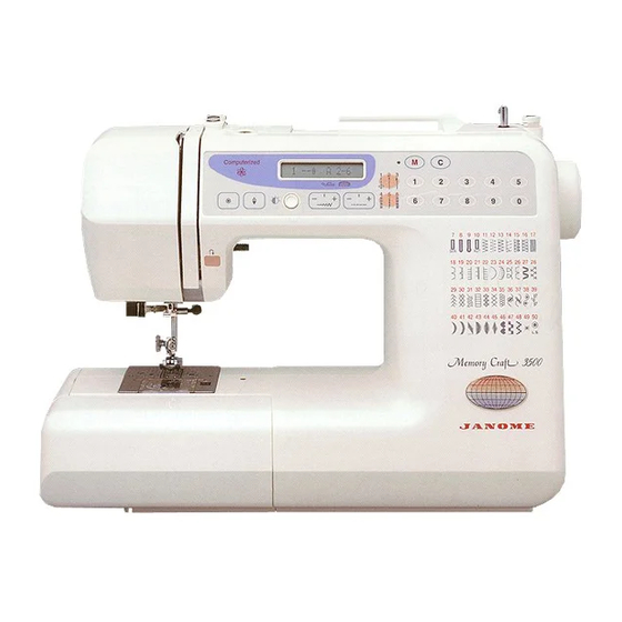
Summary of Contents for Janome Memory Craft 3500
- Page 1 SERVICING MANUAL MEMORY CRAFT 3500...
-
Page 2: Table Of Contents
BUTTONHOLE LEVER ATTACHING AND REMOVING ........... 23 BOARD K ATTACHING AND REMOVING ................ 24 BUTTONHOLE SENSOR ATTACHING AND REMOVING ..........25 WIRING DIAGRAM ......................26 MEMORY CRAFT 3500 DIAGNOSIS CHART ..............27 MEMORY CRAFT 3500 DIAGNOSIS CHART (NO.2) ............28 MULTIPLE LANGUAGE FUNCTION ................. 29... -
Page 3: Top Cover & Face Plate Attaching And Removing
TOP COVER & FACE PLATE ATTACHING AND REMOVING Top cover To remove: 1.Remove 3 screws (A) & (B) and top cover. To attach: 2.Attached the top cover with 3 screws (A) and (B). Face plate To remove 3.Remove 2 screws (C) and face plate. To attach 4.Attach the face plate with 2 screws (C). -
Page 4: Base & Bed Cover Attaching And Removing
BASE & BED COVER ATTACHING AND REMOVING Base To remove: 1. Remove 6 screws (A) and base. To attach: 2. Attach the base with 6 screws (A). Bed cover To remove: 3. Move the drop lever to the left, then remove 2 screws (B). 4. -
Page 5: Belt Cover Attaching And Removing
BELT COVER ATTACHING AND REMOVING BELT COVER To remove: 1. Remove 2 screws (A) and belt cover, then pull out. To attach: 2. Attach the belt cover with 2 screws (A). -
Page 6: Front Panel Attaching And Removing
FRONT PANEL ATTACHING AND REMOVING FRONT PANEL To remove: 1. Remove the top cover, belt cover and bed cover (see page 1, 2 and 3) 2. Remove screw (A) and loose screws (B), (C), (D), (E), (F) and (G). 3. Pull out connectors (H) and remove the front panel. To attach: 4. -
Page 7: To Adjust The Presser Bar Height
TO ADJUST THE PRESSER BAR HEIGHT The standard presser bar height is 6.0 mm between the bottom surface of the foot and needle plate when the presser bar lifter is in the position. 1. Open the face plate. 2. Raise the presser foot, loosen the presser bar bracket screw and adjust the height to 6.0 3. -
Page 8: To Adjust The Needle Drop
TO ADJUST THE NEEDLE DROP When you select the pattern ( ), the needle drop should be in the center position of the needle hole in the needle plate. When the needle swings in maximum zigzag width, the distance between both edges of The needle hole on the needle plate and the needle drop position should be equal. -
Page 9: To Adjust The Needle Bar Height
TO ADJUST THE NEEDLE BAR HEIGHT The standard distance between the upper edge of the needle eye and the tip of shuttle hook should be in the range of 1.6-2.0 mm when the tip of shuttle hook meets the right side of the needle in ascending travel of needle from its left and lowest position. -
Page 10: To Adjust The Hook Timing
TO ADJUST THE HOOK TIMING When the pattern ( ) is selected, the amount of ascending travel of the needle bar From its lowest position to the position where the tip of the rotary hook exactly meets The right side of the needle should be 3.25 to 3.55 mm. 1. -
Page 11: To Adjust The Clearance Between The Needle And The Hook
TO ADJUST THE CLEARANCE BETWEEN THE NEEDLE AND THE HOOK The clearance between needle and shuttle hook should be -0.10 to +0.05 mm. If not, make an adjustment as follows: 1. Remove the needle plate and bobbin holder. 2. Replace the needle the master needle. 3. -
Page 12: To Adjust The Backlash Of Hook Drive Gear And Lower Shaft Gear
TO ADJUST THE BACKLASH OF HOOK DRIVE GEAR AND LOWER SHAFT GEAR The backlash of gears should be smooth and should be less than 0.8 mm when the tip of shuttle hook is within the width of the feed dog as shown below. 1. -
Page 13: To Adjust The Feed Dog Height
TO ADJUST THE FEED DOG HEIGHT When pressure adjusting lever is at “3” and the presser foot is lowered, the highest Position of the feed dog should be 0.75 to 0.85 mm from the surface of the needle Plate. 1. Set the pressure adjusting lever at “3” with the presser foot lowered. 2. -
Page 14: To Adjust The Upper Shield Plate Position
TO ADJUST THE UPPER SHIELD PLATE POSITION When the machine is set for zigzag stitching, the needle should start to swing 6.3 mm to 7.5 mm above the surface of the needle plate. 1. Remove top cover. 2. Turn on the power switch and select the pattern ( 3. -
Page 15: To Adjust The Upper Thread Tension
TO ADJUST THE UPPER THREAD TENSION The standard of upper thread tension should be 75g to 90g when pulling the thread (cotton thread #50) in direction a with setting the tension dial at “3” (make sure the Foot is lowered.) 1. -
Page 16: To Adjust The Stretch Feed Balance
TO ADJUST THE STRETCH FEED BALANCE When pattern “ “ is sewn with the feed balancing dial at the standard setting mark ), the sewn pattern should be as indicated by the mark “0” the following figure. 1. Set the pattern “ “, and the feed balancing dial at standard setting mark ( 2. -
Page 17: To Replace And Adjust The Threader Plate
TO REPLACE AND ADJUST THE THREADER PLATE If the needle threader plate is broken or bent, replace it as follows: To replace: 1. Turn the hand wheel toward you until the needle bar reaches its highest po-sition and lower the needle threader knob as far as it will go. 2. -
Page 18: To Adjust The Buttonhole Lever
TO ADJUST THE BUTTONHOLE LEVER A) Buttonhole lever guide 1. Attach the automatic buttonhole foot (R). 2. Loosen the set screw (A) and leave the clearance of 2.9mm (I) between the spring holder and slider (B) by moving the buttonhole lever guide (K). In this condition, the buttonhole lever (E) should touch the spring holder (C) slightly. -
Page 19: Board A Attaching And Removing
BOARD A ATTACHING AND REMOVING To remove: 1. Remove the front cover unit. 2. Pull out 8 connectors from the board A. 3. Remove 4 screws and board A. To attach: 4. Follow the above procedure in reverse. -
Page 20: Board C Attaching And Removing
BOARD C ATTACHING AND REMOVING To remove: 1. Remove the front panel unit (see page 4). 2. Loosen screws (A). (B), (C) and (D), and remove screws (E) and (F). 3. Remove the rear cover. 4. Pull out the 4 connectors and remove screws (G). 5. -
Page 21: Board C And Fuse Attaching And Removing
BOARD C AND FUSE ATTACHING AND REMOVING To remove: 1. Remove the rear cover. 2. Remove 3 screws (A) and board C (see page 18). 3. Remove 3 screws (B) and remove case cover. 4. Replace fuse or board C. To attach: 5. -
Page 22: Dc Motor Unit Attaching And Removing
DC MOTOR UNIT ATTACHING AND REMOVING DC MOTOR To remove: Remove the front panel unit (see page 4). Remove the machine socket unit (see page 22) (no need to pull out the connectors) Cut the cord binder and pull out the motor connector from board A. Remove the screw (A) and cord guide. -
Page 23: Transformer Unit Attacing And Removing
TRANSFORMER UNIT ATTACHING AND REMOVING TRANSFORMER UNIT To remove: 1. Remove the front panel unit (see page 4). 2. Remove the board A and C (page 17) and machine socket unit (page 22). 3. Pull out the connectors for the transformer from the board C. 4. -
Page 24: Machine Socket Unit Attaching And Removing
MACHINE SOCKET UNIT ATTACHING AND REMOVING To remove: 1. Remove the front panel unit, board C and base unit. 2. Cut off the cord binder and pull out the connectors from boards A and C. 3. Remove 2 screws and machine socket unit. To attach: 4. -
Page 25: Buttonhole Lever Attaching And Removing
BUTTONHOLE LEVER ATTACHING AND REMOVING To remove: 1. Remove set screw and buttonhole shield plate. 2. Remove the snap ring. 3. Pull the buttonhole lever toward you, and remove it. To attach: 4. Insert the shaft into the holes of the buttonhole lever unit (with the buttonhole shield plate removed), and attached the buttonhole lever with the snap ring. -
Page 26: Board K Attaching And Removing
BOARDS F AND K ATTACHING AND REMOVING Board K To remove: 1. Remove the front panel unit (see page 4). 2. Remove the 9 screws. 3. Pull out the connector from board F and remove board K. To attach: 4. Follow the above procedure in reverse. Board F To remove: 1. -
Page 27: Buttonhole Sensor Attaching And Removing
BUTTONHOLE SENSOR ATTACHING AND REMOVING BUTTONHOLE SENSOR UNIT To remove: 1. Remove the front panel (see page 4). 2. Remove screw (A) and remove the buttonhole sensor unit from the sensor set plate. 3. Pull out the connector of buttonhole sensor unit from the board K. 4. -
Page 28: Wiring Diagram
WIRING DIAGRAM The connectors of the electrical components should be connected to the respective positions shown in the figure below. A. Upper shaft sensor E. Feed stepping motor unit B. Buttonhole sensor DC motor unit C. Machine socket (secondary circuit) G. -
Page 29: Memory Craft 3500 Diagnosis Chart
MEMORY CRAFT 3500 DIAGNOSIS CHART (Procedure 1) If nothing happens on the machine when turned on the power switch is, turn off the power switch and do following: 1. Check all wire connections and recheck. 2. Replace the machine socket and recheck. -
Page 31: Multiple Language Function
MULTIPLE LANGUAGE FUNCTION The display language can be changed if necessary, as illustrated bellow. 1. Remove the top cover unit, 2. Move the DIP switches with the end of the lint brush (example). 3. Replace the top cover unit after adjustment.
Need help?
Do you have a question about the Memory Craft 3500 and is the answer not in the manual?
Questions and answers
Where is the beeper located