Elkay EZ Series Installation, Care & Use Manual
Versatile bottle filling stations & coolers
Hide thumbs
Also See for EZ Series:
- Installation, care & use manual (18 pages) ,
- Installation & use manual (10 pages) ,
- Installation & use manual (30 pages)
Advertisement
Quick Links
EZSTLDWS*1D EZSTLRDWS*1D EZSTL8WS*1D, 2D, 3D EZSTLR8WS*1D
LZSTLDWS*1D LZSTLRDWS*1D LZSTL8WS*1D, 2D, 3D LZSTLR8WS*1D
INSTALLATION, CARE & USE MANUAL
Manual de Instalación, Cuidado y Utilización
Manuel d'installation/entretien/utilisation
EZ
& LZ™ Series Versatile Bottle Filling Stations & Coolers
™
EZ™ & LZ™ Serie versatil Botella Bombas y Enfriadores
EZ™ & LZ™ Stations versatile de Remplissage de Bouteille Série et Refroidisseurs
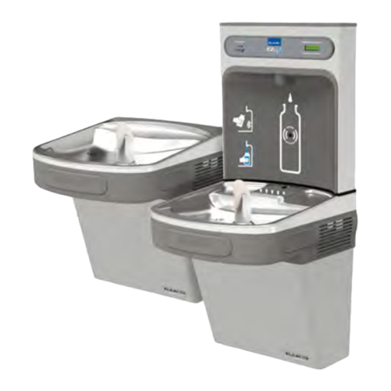
*Versatile Cooler Model LZSTL8WSLK
alternate installations
*Versatile Cooler Model LZSTL8WSLK
configuration as shipped
*Versatile cooler design allows units to be
installed either left-hand high and right-hand low
or left-low and right high.
Basin change may be required. See desired
rough-in to help determine if the basin change is
necessary.
Page 1
1000001733 (Rev. J - 06/16)
Advertisement


Need help?
Do you have a question about the EZ Series and is the answer not in the manual?
Questions and answers