Table of Contents
Advertisement
Advertisement
Chapters
Table of Contents
Troubleshooting

Subscribe to Our Youtube Channel
Related Manuals for Ryobi BT3100K


Summary of Contents for Ryobi BT3100K
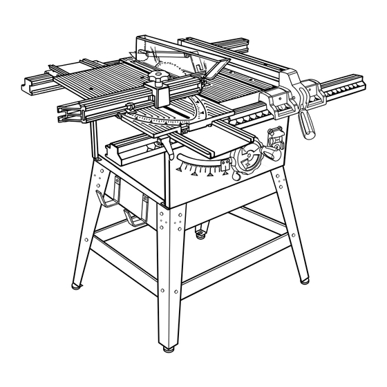
- Page 1 BT3100K 254 mm TABLE SAW WITH KIT OWNER’S OPERATION MANUAL N197...
-
Page 2: Table Of Contents
TABLE OF CONTENTS ■ Product Specifications ..........2 To Check, Replace or Adjust The Riving Knife ■ Rules for Safe Operation ........3-6 and Blade Guard Assembly ....... 24 To Adjust the Blade Depth ........25 ■ Glossary of Terms For Woodworking ...... 7 To Adjust the Blade Angle ........ -
Page 3: Rules For Safe Operation
For Carefully read through this entire operator's manual service we suggest you return the tool to your nearest Ryobi before using your new saw. Pay close attention to the AUTHORISED SERVICE CENTRE for repair. When servic- Rules For Safe Operation and all Safety Alert Symbols ing, use only identical Ryobi replacement parts. - Page 4 RULES FOR SAFE OPERATION CHECK DAMAGED PARTS. Before further use of the tool, SAFETY RULES a guard or other part that is damaged should be carefully checked to ensure that it will operate properly and perform FOR YOUR OWN SAFETY, READ INSTRUCTION its intended function.
- Page 5 RULES FOR SAFE OPERATION Use outdoor extension leads. When the tool is used outdoors, PROVIDE adequate support to the rear and sides of the use only extension cords intended for outdoor use and so saw table for wide or long work pieces. marked.
-
Page 6: Rules For Safe Operation
RULES FOR SAFE OPERATION SAFETY AND INTERNATIONAL SYMBOLS (Fig. 1a&1b&1c) This operator's manual describes safety and international symbols and pictographs that may appear on this product. Read the operator's manual for complete safety, assembly, operating and maintenance, and repair information. MEANING MEANING SYMBOL... -
Page 7: Glossary Of Terms For Woodworking
GLOSSARY OF TERMS Non-Through Cuts Anti-Kickback Pawls (Fingers) Any cutting operation where the blade does not extend Device which, when properly installed and maintained, is completely through the thickness of the workpiece. designed to stop the workpiece from being kicked back toward the front of the saw during a ripping operation. -
Page 8: Unpacking And Tools Needed
UNPACKING Your Model BT3100K Table Saw is shipped complete in one The saw is factory set for accurate cutting. After assem- carton and includes two table extensions, a rip fence, a mitre bling it, check for accuracy. If shipping has influenced the... -
Page 9: Loose Parts List
LOOSE PARTS LIST Fig. 3 Description Quan. Description Quan. Rip Scale Indicator .......... 1 Screw .............. 1 Screw .............. 1 Washer ............1 Hex Nut ............1 Knob ..............1 End Plug ............4 Adjusting Clamp ..........1 Rip Fence ............1 Mitre Fence With Mitre Indicator and Locator Sliding Mitre Table .......... -
Page 10: Loose Parts List
LOOSE PARTS LIST The following items are included with your table saw leg stand. Fig. 4 A. Storage Bracket .............4 H. Carriage Bolt (5/16-18 x 3/4 in.) ......24 B. Screw (1/4-20 x 1/2 in. Pan Hd.)......4 I. Upper Brace ............2 C. -
Page 11: Features
FEATURES Your saw is designed to perform as a versatile, accurate, • front and rear guide rails with an easy-to-read scale on precision cutting tool that is easy to operate. front rail It is equipped with the following features for convenience, •... -
Page 12: Operating Components
Your Ryobi BT3100K table saw features a receptacle on the right side of the cabinet that permits use of accessories. Use only accessories that are listed for use with this tool. When... -
Page 13: Blades
FEATURES BLADES It is recommended that you use only the RYOBI 254mm (10in) Combination Blade, which is for use with the BT3100K Table Saw. You will get maximum performance with the following features: • 36 precision ground, micro-grain carbide teeth •... -
Page 14: Assembly
ASSEMBLY Assembly is best done in the area where the saw will be used. When you remove the table saw base, loose parts, and hardware from the packing materials, check all items with the loose parts list and drawing. If you are unsure about the description of any part, refer to the drawing. -
Page 15: Assembly Storage Brackets
ASSEMBLY ASSEMBLING STORAGE BRACKETS UPPER BRACE STORAGE BRACKET(S) See Figure 9. ■ Take storage brackets from loose parts. ■ Take the following hardware from the leg stand hardware bag: 4 screws (1/4-20 x1/2 in. Pan Hd.) 4 hex nuts (1/4-20) 4 washers (1/4 in.) ■... -
Page 16: To Install Mitre Table And Fence
ASSEMBLY ■ Check to make sure the rail clamps will securely clamp REAR RAIL the rail before sliding the entire assembly into position. If END PLUG not, tighten the square rail holder nut one-fourth (1/4) turn and recheck. ■ Slide the rail into position over both clamps and secure. ■... -
Page 17: To Install Accessory Table And Rip Fence
ASSEMBLY TO INSTALL ACCESSORY TABLE AND RIP ACCESSORY FENCE TABLE ■ Place the accessory table on the front and back rails, fitting the lips into the top slot of the rear rail. Position the REAR RAIL slot on the underside of the accessory table onto the front LOCK LEVER rail and tighten the lever securely. -
Page 18: Blade And Guard Assembly
ASSEMBLY BLADE AND GUARD ASSEMBLY SMALL HEX WRENCH WARNING: Do not connect to power supply until assembly is complete. Failure to comply could result in accidental starting and possible serious injury. TO CHECK SAW BLADE INSTALLATION ■ To check the saw blade, first remove the screw holding the throat plate in place. -
Page 19: To Install Blade Guard Assembly
ASSEMBLY ■ Check the blade guard assembly for clearances and free ■ Blade alignment with the riving knife can be adjusted for different blade widths. Refer to Settings and Adjustments movement. Reinstall the throat plate into the opening, in the Operations Section. Before continuing, read To lower the blade and secure the attachment screw. -
Page 20: Operation
OPERATION ■ Use the right type of blade for the cut being made. BASIC OPERATION OF THE TABLE SAW ■ Use the blade guard assembly for all through cuts. A table saw can be used for straight-line cutting operations such as cross cutting, ripping, mitring, beveling, and com- CUTTING AIDS pound cutting. -
Page 21: Types Of Cuts
OPERATION ■ The kerf (the cut made by the blade in the wood) will be wider than the blade to avoid overheating or binding. Make allowance for the kerf when measuring wood. ■ Make sure the kerf is made on the waste side of the measuring line. -
Page 22: Featherboard
Kickback can result from the featherboard pinching the workpiece and binding the blade in the saw The featherboard is an excellent project for your BT3100K. kerf if positioned improperly. Failure to heed this warning Select a solid piece of timber approximately 19mm thick, 92mm can result in serious personal injury. -
Page 23: Settings And Adjustments
OPERATION SETTINGS AND ADJUSTMENTS BLADE THROAT GUARD PLATE TO REMOVE THE BLADE See Figures 25 - 27. Use the two wrenches supplied with the saw in this proce- dure to replace the blade. WARNING: Unplug your saw and make sure the blade guard assembly is installed and working properly to avoid serious personal injury. -
Page 24: To Check, Replace Or Adjust The Riving Knife And Blade Guard Assembly
OPERATION TO CHECK, REPLACE OR ADJUST THE RIVING KNIFE AND BLADE GUARD ASSEMBLY The riving knife is mounted between several shims that can be relocated as needed to centre the knife behind the blade. It is held in place by two bolts and hex nuts at its base. The bolts are set in slots that permit front-to-back adjustment. -
Page 25: To Adjust The Blade Depth
OPERATION TO ADJUST THE BLADE DEPTH The blade depth should be set so that the outer points of the blade are higher than the workpiece by approximately 3mm to 6mm but the lowest points (gullets) are below the top surface. See Figure 31. WARNING: Unplug the saw and make sure the blade guard assembly is installed and working properly to avoid serious personal... -
Page 26: To Lock The Mitre Table
OPERATION TO LOCK MITRE TABLE See Figure 34. MITRE The mitre table slides to let the operator slide the workpiece SLIDE LOCK across the saw. A mitre slide lock is mounted on the front of the mitre table to lock it in place. The mitre slide lock is placed in a slot on the base to align the mitre table with the front edge of the saw table. -
Page 27: To Make A Mitre Cut
OPERATION ■ Make sure the wood is clear of the blade before turning on BLADE the saw. See Figure 35. MITRE FENCE GUARD ASSEMBLY ■ To turn saw on ( ), lift switch cover and press switch button. Then lower switch cover. ■... -
Page 28: To Make A Bevel Cross Cut
OPERATION TO MAKE A BEVEL CROSS CUT MITRE FENCE See Figure 39. ADJUSTING CLAMP It is recommended that you place the piece to be saved on QUICK STOP the left side of the blade and that you make a test cut on scrap wood. -
Page 29: To Make A Compound Mitre Cut
OPERATION ■ Once the blade has made contact with the workpiece, ACCESSORY SLIDING MITRE use the hand closest to the rip fence to guide it. Make TABLE ASSEMBLY TABLE sure the edge of the workpiece remains in solid contact with both the rip fence and the surface of the table. If ripping a narrow piece, use a push stick to move the piece through the cut and past the blade. -
Page 30: To Make Non-Through Cuts
OPERATION TO MAKE NON-THROUGH CUTS FEATHERBOARD Non-through cuts can be made with the grain (ripping) or across the grain (crosscut). The use of a non-through cut is essential to cutting grooves, rebates, and dadoes. This is the only type cut that is made without the blade guard installed. Make sure the blade guard assembly is reinstalled upon completion of this type of cut. -
Page 31: To Make Dado Cuts
OPERATION ■ When mounting dado blades, make sure both the inner TO MAKE DADO CUTS blade washer and outer blade washer are used. A dado is a non-through cut and typically refers to a channel ■ Replace the throat plate with optional Dado Throat Plate. cut, both with the grain and across the grain. -
Page 32: Maintenance
MAINTENANCE ■ To maintain the table surfaces, fence, and rails, periodically GENERAL MAINTENANCE apply paste wax to them and buff to provide smooth functioning. To prevent work from slipping during cutting operation, DO NOT wax the working face of the mitre WARNING: fence. -
Page 33: To Set Blade To 0 Or 45 Degrees
MAINTENANCE ° BOLT WARNING: Before performing any adjustment, make sure the tool is unplugged from the power supply and the switch is in the off ( ) position. Failure to head this warning could result in serious personal injury. ° °... -
Page 34: To Adjust The Bevel Locking Lever
MAINTENANCE ■ Make two or three test cuts on scrap wood. If the cuts are BLADE not true, repeat the process. ADJUSTING HANDLE WARNING: SET SCREW Before plugging the saw back in to make test cuts, make sure the switch is in the off ( ) position and the blade guard is in place. -
Page 35: To Adjust The Front And Rear Rail Clamps
MAINTENANCE TO ADJUST THE FRONT AND REAR RAIL CLAMPS WASHER See Figure 49. The rail clamps are located below the rails and ensure tight attachment of the rail. Following extended use, the rail holder nut inside the rails may need adjusting. ■... -
Page 36: Checking Sliding Mitre Table Assembly
MAINTENANCE CHECKING SLIDING MITRE TABLE ASSEMBLY To Check Mitre Base Parallelism: WARNING: Begin by unplugging your saw. Failure to unplug saw could result in accidental starting causing possible serious injury. ■ Set saw up as if you were preparing to make a cut. Tighten rail clamps, mitre locking clamps, adjusting clamp, etc. -
Page 37: Making Adjustments To Sliding Mitre Fence Table Assembly
MAINTENANCE To Check Mitre Fence Alignment See Figure 53. The mitre fence must be perpendicular to the blade when set at zero degrees. WARNING: Begin by unplugging your saw. Failure to unplug saw could result in accidental starting causing possible serious injury. -
Page 38: Maintenance
MAINTENANCE MITRE TABLE WARNING: HEX NUT Begin by unplugging your saw. Failure to unplug saw could result in accidental starting causing possible serious injury. TO ADJUST THE MITRE FENCE ■ Set the mitre fence (H) at 0° as shown in figure 53. Mitre indicator (I) should be set precisely on 0°... -
Page 39: Troubleshooting
TROUBLE SHOOTING PROBLEM CAUSE SOLUTION Excess vibration. Blade is out of balance. Replace blade. Blade is damaged. Replace blade. Saw is not mounted securely. Tighten all hardware. Work surface is uneven. Reposition on flat surface. Adjust legs of table saw stand. Blade is warped Check Saw Blade Installation on page 20. -
Page 40: Troubleshooting
Locking lever is not at full left Move locking lever to left. position. Motor labors in rip cut. Blade not proper for rip cut. Change blade; rip blade typically has fewer teeth such as Ryobi 4650324, 24 tooth, carbide rip blade. Page 40... - Page 41 NOTES NOTES Page 41...
- Page 42 RYOBI NEW ZEALAND PTY. LTD. AUCKLAND: 27 Clemow Drive, Mt Wellington, N.Z. Tel: (09) 573 0230 - Free Call: 0800 279 624 - Fax: (09) 573 0231 - www.ryobi.co.nz Contact during normal business hours. This Guarantee Form Should Be Retained By The Customer At All Times For your record and to assist in establishing date of purchase (necessary for in-guarantee service) please keep your purchase docket and this form completed with the following particulars.
Need help?
Do you have a question about the BT3100K and is the answer not in the manual?
Questions and answers