Table of Contents
Advertisement
Your table saw has been engineered and manufactured to our high standards for dependability, ease of operation, and
operator safety. Properly cared for, it will give you years of rugged, trouble-free performance.
WARNING:
To reduce the risk of injury, the user must read and understand the operator's manual before using
this product.
Thank you for your purchase.
SAVE THIS MANUAL FOR FUTURE REFERENCE
OPERATOR'S MANUAL
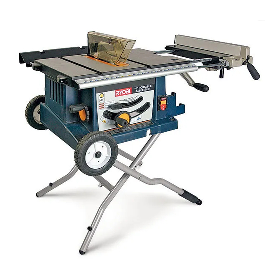
10 in. (254 mm) TABLE SAW
BTS20R-1
Advertisement
Table of Contents

Subscribe to Our Youtube Channel
Related Manuals for Ryobi BTS20R-1


Summary of Contents for Ryobi BTS20R-1
- Page 1 OPERATOR’S MANUAL 10 in. (254 mm) TABLE SAW BTS20R-1 Your table saw has been engineered and manufactured to our high standards for dependability, ease of operation, and operator safety. Properly cared for, it will give you years of rugged, trouble-free performance.
-
Page 2: Table Of Contents
The replacement power tool will be covered by the limited warranty for the balance of the two year period from the date of the original purchase. WHAT THIS WARRANTY COVERS: This warranty covers all defects in workmanship or materials in your RYOBI power tool ®... -
Page 3: General Safety Rules
GENERAL SAFETY RULES SECURE WORK. Use clamps or a vise to hold work when WARNING: practical. It’s safer than using your hand and frees both hands to operate tool. Read and understand all instructions. Failure to follow DON’T OVERREACH. Keep proper footing and all instructions listed below, may result in electric shock, balance at all times. -
Page 4: Specific Safety Rules
GENERAL SAFETY RULES work or around or over the blade while blade is rotating. use brake fluids, gasoline, petroleum-based products, or Do not attempt to remove cut material when blade is any solvents to clean tool. moving. STAY ALERT AND EXERCISE CONTROL. Watch what ... - Page 5 SPECIFIC SAFETY RULES IF THE POWER SUPPLY CORD IS DAMAGED, it must NEVER perform any operation “freehand” which means be replaced only by the manufacturer or by an authorized using only your hands to support or guide the workpiece. service center to avoid risk.
-
Page 6: Symbols
SYMBOLS Some of the following symbols may be used on this tool. Please study them and learn their meaning. Proper interpretation of these symbols will allow you to operate the tool better and safer. SYMBOL NAME DESIGNATION/EXPLANATION Volts Voltage Amperes Current Hertz Frequency (cycles per second) -
Page 7: Symbols
If you do not understand ing, use only identical replacement parts. the warnings and instructions in the operator’s manual, do not use this product. Call Ryobi customer service for assistance. WARNING: The operation of any power tool can result in foreign objects being thrown into your eyes, which can result in severe eye damage. -
Page 8: Electrical
ELECTRICAL EXTENSION CORDS SPEED AND WIRING Use only 3-wire extension cords that have 3-prong ground- The no-load speed of this tool is approximately 4,800 ing plugs and 3-pole receptacles that accept the tool’s plug. rpm. This speed is not constant and decreases under a When using a power tool at a considerable distance from the load or with lower voltage. -
Page 9: Glossary Of Terms
GLOSSARY OF TERMS Anti-Kickback Pawls (radial arm and table saws) Non-Through Cuts A device which, when properly installed and maintained, Any cutting operation where the blade does not extend is designed to stop the workpiece from being kicked back completely through the thickness of the workpiece. toward the front of the saw during a ripping operation. -
Page 10: Features
FEATURES PRODUCT SPECIFICATIONS Blade Diameter ............10 in. Input ......... 120 V, 60 Hz, AC only, 15 amps Blade Arbor .............. 5/8 in. No Load Speed ........4,800 r/min. (RPM) Cutting Depth at 0° ..........3-5/8 in. Net Weight ............89.73 lbs. Cutting Depth at 45°... - Page 11 FEATURES KNOW YOUR TABLE SAW WARNING: See Figure 2. The safe use of this product requires an understanding of Do not use blades rated less than the speed of this tool. the information on the tool and in this operator’s manual as Failure to heed this warning could result in personal well as a knowledge of the project you are attempting.
- Page 12 FEATURES OPERATING COMPONENTS WARNING: The upper portion of the blade projects up through the table, surrounded by an insert called the throat plate. To cut Always remove the switch key when the tool is not in wood at a bevel, the blade must be tilted, using the bevel use and keep it in a safe place.
-
Page 13: Tools Needed
TOOLS NEEDED The following tools (not included) are needed for making adjustments: HEX KEY, 4 mm PHILLIPS SCREWDRIVER WRENCH (2) 1/2 in., 8 mm COMBINATION SQUARE FRAMING SQUARE Fig. 4 LOOSE PARTS LIST Rip Fence ..............1 Large Wrench ..............1 Miter Gauge ..............1 Small Wrench ..............1 Blade Guard Assembly ...........1 Bumper ................2... -
Page 14: Assembly
ASSEMBLY UNPACKING WARNING: This product requires assembly. Do not lift the saw without help. Hold it close to your Carefully lift saw from the carton and place it on a level work surface. body. Keep your knees bent and lift with your legs, not your back. -
Page 15: Assembling Bumpers
ASSEMBLY ASSEMBLING WHEELS See Figures 6 - 7. Remove the following hardware from the bag: 2 wheels 2 washers 2 shoulder bolts Place the table saw on end. Loosen bolts on each side of the table saw by turning counterclockwise. - Page 16 ASSEMBLY OPENING THE LEG STAND See Figure 9. NOTE: You can also refer to the blue label on the right-hand side of the table saw for setup procedures. Standing to the front side of the table saw, use your left hand to pull the leg stand latch towards you.
- Page 17 ASSEMBLY REMOVING/REPLACING THE THROAT THROAT PLATE PLATE See Figure 10. SCREW Unplug the saw. Lower the blade by turning the height adjusting handwheel counterclockwise. Loosen the screws in the throat plate. Lift the throat plate from the saw. ...
- Page 18 ASSEMBLY TO INSTALL BLADE GUARD ASSEMBLY See Figure 13. SPREADER Lower the blade by turning the height adjusting handwheel clockwise. SHIMS Using the small wrench, install the blade guard assembly by loosening the two hex nuts enough to slide the spreader down between the shims.
-
Page 19: Operation
OPERATION Using the wrong blade for the type of cut WARNING: Not following correct operating procedures Misusing the saw Do not allow familiarity with tools to make you careless. Failing to use the anti-kickback pawls Remember that a careless fraction of a second is sufficient ... -
Page 20: Cutting Tips
OPERATION TYPES OF CUTS See Figure 17. There are six basic cuts: 1) the cross cut, 2) the rip cut, 3) the miter cut, 4) the bevel cross cut, 5) the bevel rip cut, and 6) the compound (bevel) miter cut. All other cuts are combina- tions of these basic six. - Page 21 OPERATION TO CHANGE BLADE DEPTH See Figure 18. The blade depth should be set so that the outer points of the blade are higher than the workpiece by approximately 1/8 in. to 1/4 in. but the lowest points (gullets) are below the top surface.
- Page 22 OPERATION TO USE THE RIP FENCE See Figure 21. Place the front lip on the front rail and push slightly toward the rear of the unit. RIP FENCE Lower the rear of the rip fence onto the guide surfaces on top of the rear rail.
- Page 23 OPERATION HEELING (PARALLELING) THE BLADE TO THE MITER GAUGE GROOVE SCREWS See Figures 25 - 27 . WARNING: The blade must parallel the miter gauge slot so the wood does not bind resulting in kickback. Failure to do so could result in serious personal injury.
-
Page 24: Making Cuts
OPERATION MAKING CUTS The blade provided with your saw is a high-quality combina- SWITCH tion blade suitable for ripping and crosscut operations. WARNING: Do not use blades rated less than the speed of this tool. Failure to heed this warning could result in personal injury. - Page 25 OPERATION MAKING A MITER CUT MITER CUT See Figure 30. It is recommended you make test cuts on scrap wood. BLADE MITER GAUGE GUARD ASSEMBLY WARNING: Make sure the blade guard assembly is installed and working properly to avoid serious personal injury. ...
-
Page 26: Making A Bevel Cross Cut
OPERATION MAKING A BEVEL CROSS CUT BEVEL CROSS CUT See Figure 32. MITER It is recommended that you place the piece to be saved on GAUGE the left side of the blade and that you make a test cut on scrap wood. - Page 27 OPERATION MAKING A COMPOUND MITER CUT NON-THROUGH CUT It is recommended that you place the piece to be saved on the left side of the blade and that you make a test cut on FEATHERBOARD scrap wood first. WARNING: Make sure the blade guard assembly is securely installed and working properly to avoid serious personal injury.
-
Page 28: Operation
(max. dado width 13/16 in.). Do not use blades rated less Never feed wood with your hands when making any non- than the speed of this tool. (The Ryobi part number for the through cut such as rabbets or dadoes. -
Page 29: Adjustments
ADJUSTMENTS BLADE WARNING: THROAT GUARD PLATE Before performing any adjustment, make sure the tool is unplugged from the power supply. Failure to heed this warning could result in serious personal injury. The table saw has been adjusted at the factory for making very accurate cuts. - Page 30 ADJUSTMENTS TO SET BLADE INDICATOR AND BEVEL STOPS AT 0° OR 45° (SQUARING THE BLADE) See Figure 38. The angle settings of your saw have been set at the factory and, unless damaged in shipping, should not require set- ting during assembly. After extensive use, it may need to be checked.
-
Page 31: Maintenance
ADJUSTMENTS TO CHECK THE ALIGNMENT OF THE RIP FENCE CLAMP TO THE BLADE RIP FENCE SCREW See Figure 40. Raise the locking handle to permit the rip fence to be moved. Place a framing square beside the blade and move the BLADE rip fence up to the square. -
Page 32: Troubleshooting
2. Work is fed too fast. 2. Slow the feed rate. 3. Wood is warped. 3. Replace wood. 4. Blade is heeling. 4. Call Ryobi Technical Service at 1-800-525-2579. Wood edges away from rip 1. Blade not properly sharpened. 1. Have blade resharpened. - Page 33 NOTES NOTES Page 33...
- Page 34 When ordering repair parts, always give the following information: BTS20R-1 • MODEL NUMBER • SERIAL NUMBER Ryobi is a registered trademark of Ryobi Limited used under license. ® ® ONE WORLD TECHNOLOGIES, INC. 1428 Pearman Dairy Road, Anderson, SC 29625 Phone 1-800-525-2579 www.ryobitools.com...
Need help?
Do you have a question about the BTS20R-1 and is the answer not in the manual?
Questions and answers