Marantz PM8003 Service Manual
Hide thumbs
Also See for PM8003:
- User manual (23 pages) ,
- Guía del usuario (17 pages) ,
- Mode d'emploi (17 pages)
Table of Contents
Advertisement
Service
Manual
SECTION
1. TECHNICAL SPECIFICATIONS ........................................................................................... 1
2. ALIGNMENTS ....................................................................................................................... 2
3. SERVICE MODE ................................................................................................................... 4
4. PROTECTION MODE ........................................................................................................... 5
5. WRITING MAIN MICROPROCESSOR PROCEDURE ......................................................... 7
6. WIRING DIAGRAM ............................................................................................................. 25
7. BLOCK DIAGRAM .............................................................................................................. 27
8. SCHEMATIC DIAGRAM ...................................................................................................... 29
9. PARTS LOCATION .............................................................................................................. 37
10. EXPLODED VIEW AND PARTS LIST ................................................................................. 47
11. MICROPROCESSOR AND IC DATA ................................................................................... 51
12. ELECTRICAL PARTS LIST ................................................................................................. 56
13. ABOUT REPLACE THE MICROPROCESSOR WITH A NEW ONE ............................... 72
Please use this service manual with referring to the user guide ( D.F.U. ) without fail.
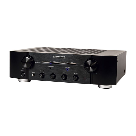
INTEGRA TED AMPLIFIER PM8003
PHONO
CD
INPUT SELECTOR
POWER AMP DIRECT
ST ANDBY
SPEAKERS
A
POWER ON/OFF
B
OFF
PHONES
A+B
-
TABLE OF CONTENTS
PM8003
Integrated Amplifier
TUNER
AUX/DVD
1
RECORDER
2
MUTE
VOLUME
SOURCE DIRECT
MIN
BASS
TREBLE
BALANCE
+
-
+
L
R
PM8003 /
F N/N1SG
/N1B/U1B
MAX
PAGE
Part no. 90M25AJ855010
First Issue 2008.08
MZ
Advertisement
Table of Contents

Related Manuals for Marantz PM8003


Summary of Contents for Marantz PM8003
- Page 1 Service PM8003 / F N/N1SG /N1B/U1B Manual Integrated Amplifier INTEGRA TED AMPLIFIER PM8003 PHONO TUNER AUX/DVD RECORDER MUTE INPUT SELECTOR VOLUME POWER AMP DIRECT SOURCE DIRECT ST ANDBY SPEAKERS BASS TREBLE BALANCE POWER ON/OFF PHONES TABLE OF CONTENTS SECTION PAGE 1.
- Page 2 MARANTZ Parts for your equipment are generally available to our National Marantz Subsidiary or Agent. ORDERING PARTS : Parts can be ordered either by mail or by Fax.. In both cases, the correct part number has to be specified.
-
Page 3: Technical Specifications
Depth ........... 15 inch (379mm) mpedance Weight (Amplifier) ........ 26.5 lbs (12.0kg) .....1.6V/600Ω 17-5/16 (440) ONO input level (1kHz) ......100mV INTEGRATED AMPLIFIER PM8003 z ~ 20kHz) ..±0.5dB ......87dB UX/DVD, RECORDER ......90dB T IN ..... 106dB (unit : inch (mm)) ...... -
Page 4: Alignments
2. ALIGNMENTS 2. ALIGNMENTS アイドリング電流調整 1. Idling Current Alignment Digital Voltmeter Digital Voltmeter L ch R ch T.P. T.P. J707 R707 R708 J708 P701 調整手順 Adjustment Procedure 調整時は必ず電源電圧を定格電圧に合わせてください。 Set the power voltage to rated voltage for this adjustment. 基板上の半固定抵抗 と でアイドリング電流... - Page 5 2. DC Offset Voltage Adjustment Digital Voltmeter Digital Voltmeter R ch L ch PHONO PRE OUT POWER AMP SPEAKERS DIRECT IN SYSTEM A MODEL NO. PM8003 AC IN REMOTE CONTROL TUNER RECORDER 1 RECORDER 2 / D V D P101 R639 R640 調整手順...
-
Page 6: Service Mode
3. SERVICE MODE 3. SERVICE MODE 確認 Microprocessor (QU01) version check Microprocessor (QU01) version 本機に電源ケーブルを接続します。 Connect the mains cord into the unit. ボタンを押しながら、 ボタンを POWER button with pressing the SOURCE SOURCE DIRECT POWER Press the 押します。 DIRECT button on the Unit. のバージョンが... -
Page 7: Protection Mode
動作について 4. PROTECTION MODE 4. PROTECTION マイコン の と の説明。 (QU01) PROT-1 (pin6) PROT-2 (pin7) Explanation of microprocessor (QU01) [PROT-1 (pin6) and PROT-2 (pin7)]. は、パワーアンプの下記の異常動作を検出 [A] The PROT-1 (pin6) is the port to detect the following [A] PROT-1 (pin6) するポートです abnormalities of the Power AMP スピーカー出力端子の... - Page 8 は、電源回路の異常を検出するポートです [B] PROT-2 (pin7) To check if the amp is in order, switch off the unit and switch パワーアンプ用電源回路の異常を検出。 it on again one minute later. This action will deactivate パワーアンプ用電源の と の中点電圧を監視 +48V -48V the protection operation. If the PROT-1 (pin6) remains し、...
-
Page 9: Writing Main Microprocessor Procedure
5. WRITING MAIN MICROPROCESSOR 5. WRITING MAIN MICROPROCESSOR PROCEDURE PROCEDURE を交換したときは へプログラムを書き込む必要が QU01 QU01 Microprocessor needs writing software, when a あります。下記手順に沿って書き込みをしてください。 microprocessor (QU01) is replaced. 必要機器 NECESSARY EQUIPMENT または 、 ポートつき • Windows PC (2000 or XP, with Serial Port) •... - Page 10 フォルダをダブルクリックして開きます。 TM86FH47pass Double click the TM86FH47pass folder. をダブルクリックします。 FlashProg.exe. FlashProg.exe Double click...
- Page 11 をクリックします。 Device Click Device. をクリックします。 Click Apply. Apply...
- Page 12 に が入力されます。 TMP86FH47 appear in Chosen Device. Chosen Device TMP86FH47 をクリックし、 をクリックします。 Object File, and click Browse... Object File Browse... Click...
- Page 13 から を選び、書き込 iHEX Fomat[*.h16,*.h20] in Files of type. Files of type iHEX Fomat[*.h16,*.h20] Choose み用データファイルを選択して をクリックします。 Open Choose writing data, and click Open. 書き込むファイル名は変わることがあります。 PM7003_V09.h16 をクリックします。 Communication. Communication Click PM7003...
- Page 14 から接続する 番号を選びます。 COM port number in COM port. COM Port COM Port Choose から を選択します。 9600 Choose 9600 in Data Rate. Data Rate をクリックします。 Click OK. この時 フォルダに フォルダと When Setup window is closed, the tmp folder and TMP86FH47pass ファイルが作成されます。 FlashProg.ini file are created simultaneously.
- Page 15 が閉じ、 が立ち上がります。 The Flash Programmer is launched. setup Flash Programmer アイコンをクリックします。 Click setup icon. setup をクリックします。 Click Browse..Browse...
- Page 16 フォルダから を選 FlashProg.ini in TM86FH47pass folder, and TM86FH47pass FlashProg.ini Choose び、 をクリックします。 Open click Open. をクリックします。 Click PM7003...
- Page 17 本機の電源スイッチをオンにします。 Press the POWER ON/OFF button, and turn on the unit. ウィンドウの左下のステータスが Flash Programming Status indication at lower left in Flash Programming から に変わります。もし Connecting Connected Connected window is changed to "Connected" from "Connecting". に変わらないときは接続を確認してください。 When it did not changed, check the connection of FPC or RS-232C cable.
- Page 18 から を選びます。 Setup Password Select Password in Setup.
- Page 19 画面が開きます。 Setup Password Setup Password opens. ブランクマイコンに書き込む場合は、次のページへ • When writing in a blank microprocessor • 既に書き込まれたマイコンに書き込む場合 アップデート は Refer to next page • ページへ • When writing (update) in the already written-in microprocessor Refer to 19 page...
- Page 20 ブランクマイコンに書き込む場合 When writing in a blank microprocessor から にチェックを入れます。 Check Single Boot Mode in Address Mode. Address Mode Single Boot Mode 内の設定 Setting in Device Password Device Password のチェックボックスにチェックを Check Device is BLANK. Device is BLANK 入れます。 Check Hex in input type. から...
- Page 21 既に書き込まれたマイコンに書き込む場合 アップデート When writing in the already written-in microcomputer から にチェックを入れま (update) Single Boot Mode Address Mode す。 Check Single Boot Mode in Address Mode. 内の設定 Setting in Device Password Device Password にはチェ ックを入れないでください。 Do not check Device is BLANK. Device is BLANK から...
- Page 22 の設定画面が開きます。 Auto Programming opens. Auto Programming...
- Page 23 から All Erase, Programming, Verify with SUM and Flash Memory Programming All Erase, Check にチェッ Programming, Verify with SUM, File Compare File Compare in Flash Memory Programming. クを入れます。 Check Manual in Recover Process by Programming から にチ Manual Error. Recover Process by Programming Error ェックを入れます。...
- Page 24 メインマイコン への書き込みが行われます。 (QU01) Writing data is written into the microprocessor (QU01). 書き込みが成功すると下記のような画面が出ますので を Yes, when writing is successful. Click クリックします。...
- Page 25 をクリックし終了します。 Cancel Click Cancel. をクリックします。 Click Cancel. Cancel...
- Page 26 から を選び終了します。 Exit in File, and finish. File Exit Select the 本機の電源スイッチを切りケーブルを外します。 Press the POWER ON/OFF button, and turn off the unit. の 確認をしてください。 Disconnect each cable. Software Version ページの で確認します。 "3.SERVICE MODE" Check the software version. Refer to "3. SERVICE MODE" on page 4.
-
Page 27: Wiring Diagram
6. WIRING DIAGRAM J755 P591 T0 WU01 VOLUME PWB T0 JU07 J593 J592 P751 (P971) SPEAKER TERMINAL J501 W008 W401 J331 W601 J701 J709 J751 P401 PHONO AMP PWB J754 W291 J283 W602 J702 P101 MAIN PWB P701 POWER STAGE PWB W801 WA01 J821... -
Page 28: Block Diagram
7. BLOCK DIAGRAM PHONO PRE OUT RIAA POWER AMP DIRECT SOURCE DIRECT CD DIRECT DIRECT BUFFER TUNER SPEAKER-A AUX / DVD SPEAKER-B VOLUME LINE BUFFER RECORDER-1 MUTE SPEAKER-B RECORDER-2 SPEAKER-B TREBLE BALANCE RECORDER-1 BASS HEADPHONE REC BUFFER RECORDER-2 PROTECION CIRCUIT R-CH MAIN TRANS. -
Page 29: Schematic Diagram
8. SCHEMATIC DIAGRAM SPK TERMINAL PWB P751 P401 PHONO AMP PWB P401 PHONO AMP PWB R467 16.5V 16.4V J011 15.5V 15.5V 15.6V R753 1.2V 1.2V 25.5V SPK_A(L) 0.6V J012 0.6V 0.6V 0.6V 0.6V 15.0V J013 3300p C421 R461 R465 C411 SPK_B(L) 10u/35 J014... - Page 30 P101 MAIN PWB TO TONE PWB TO TONE PWB TO VOLUME PWB TO PHONO AMP PWB To PHONO AMP PWB W201 W202 J592 W291 W401 +18V +18V J501 J281 J282 J283 B 7P-MQ-C -18V -18V PH_L PH-OUT-L R659 A-GND +24VL +24VL +24VL 46.9V...
- Page 31 P751 (P971) SPEAKER TERMINAL PWB P701 POWER STAGE PWB SPK TERMINAL PWB P751 P701 POWER STAGE PWB P401 PHONO AMP PWB 47.5V FROM MAIN POWER TRANSFORMER J801 G801 47.5V R467 Q713 16.5V 34.0V 16.4V 2SC2837 0.68/4.7 J011 R713 0.6V 1.8V 15.5V 34.0V 15.5V...
- Page 32 1.9 V P201 D-GND 5.SOURSE DIRECT 0.9 V D-GND 6.RESERVED W205 D-GND RU25 P201 TONE PWB PM7003 EARTH POWER AMP DIRECT:5V JU07 PM8003 SOURCE DIRECT:5V R223 16.5V SPK_B D-GND TO SPK TERMINAL PWB QU04 KRA102M SPK_A J755 W009 TREBLE BASS C205...
-
Page 33: Parts Location
P851 B PWB 9. PARTS LOCATION P401 B PWB C291 Q401 R409 R465 C292 Q402 R410 R466 C293 Q403 R411 R467 C294 Q404 R412 R468 C295 Q405 R413 R469 C296 Q406 R414 R470 C297 Q407 R415 R471 C298 Q408 R416 R472 C299 Q409... - Page 34 P591 B PWB P101 B PWB C591 B4 C301 B15 C903 F8 Q317 C11 Q915 G8 R388 D10 R624 G10 U109 F13 U31 C5 C592 B4 C303 A15 C911 G9 Q318 B11 Q916 H8 R391 D14 R625 G6 U11 D3 U32 D5 J591 A5 C304 A15...
- Page 35 P101 B PWB 鉛フリー半田 半田付けには、鉛フリー半田 (Sn-Ag-Cu) を使用してください。 Lead-free Solder When soldering, use the Lead-free Solder (Sn-Ag-Cu).
- Page 36 PU01 B PWB CU01 B4 LU32 B9 RU23 B5 U306 B3 U334 A5 U362 A9 CU02 C4 QU01 B5 RU24 A5 U307 C3 U335 C5 U363 B9 CU03 C4 QU02 B5 RU25 B5 U308 A3 U336 B5 U364 B9 CU04 C3 QU03 C5 RU26 B5 U309 C3...
- Page 37 P701 B PWB C701 D3 J709 B6 R710 D10 R955 C4 U215 C3 U244 C7 C702 D9 J801 D6 R713 C2 R956 C8 U216 B3 U245 B7 C705 B2 Q703 C2 R714 C10 R957 C4 U217 B3 U246 B8 C706 B10 Q704 C10 R715 C2 R958 C8...
-
Page 38: Exploded View And Parts List
10. EXPLODED VIEW AND PARTS LIST 5128 F only N only Ø3X8(M) 5129 Ø3X8(M) P981 W001 J001 004Lx6 5129 5128 U only Ø3X8(M) 5126 Ø3X8(M) J003-006 5110 Ø3X8(M) Ø3X8(M)x4 J007-010 001L 5127 Ø3X8(M) 5110 5110 5110 Ø3X6(M)x6 Ø3X6(M) Ø3X6(M) 5127 5405 Ø3X8(M) 5126... - Page 39 L001 1010100040018 TRANSF. # POWER TRANSFORMER 100V L001 /N1B 1010100030088 1010100030088 TRANSF. # POWER TRANSFORMER 230V L001 /N1SG 1010100030088 1010100030088 TRANSF. # POWER TRANSFORMER 230V NOTE : "nsp" PART IS LISTED FOR REFERENCE ONLY, MARANTZ WILL NOT SUPPLY THESE PARTS.
- Page 40 00M14AJ257310 LID TOP COVER SG 001D /N1B 00M14AJ257320 LID TOP COVER BL 001D /N1SG 00M14AJ257310 LID TOP COVER SG 001D /U1B 00M14AJ257320 LID TOP COVER BL NOTE : "nsp" PART IS LISTED FOR REFERENCE ONLY, MARANTZ WILL NOT SUPPLY THESE PARTS.
-
Page 41: Microprocessor And Ic Data
11. MICROPROCESSOR AND IC DATA QU01 : TMP86FH47UG Port Setting Port name I/O use Note Name Act. Init STBY 1 VSS 2 XIN 8M Clock in 3 XOUT O XOUT 8M Clock out 4 TEST TEST L->H : PROM Mode 5 VDD u-com power supply 6 P21 (XTIN) - Page 42 TMP86FH47 signments (Top view) QU01 : TMP86FH47UG TMP86FH47 Block Diagram Program memory Address/data bus (Flash memory) TLCS-870/C Data memory Boot program Flash memory I/F (RAM) (ROM Standby control circuit Interrupt controller RESET System control TEST circuit Timing generator Time base 8-bit 16-bit -bit AD...
- Page 43 LC78211, 78212, 78213 nued from preceding page. Q391 : LC78212 No. 4817-4/6...
- Page 44 Q713/Q714 : 2SC2837Y 2SC2837 LAPT Application : Audio and General Purpose Silicon NPN Epitaxial Planar Transistor (Complement to type 2SA1186) External Dimensions MT-100(TO3P) Absolute maximum ratings Electrical Characteristics ■ (Ta=25°C) ■ (Ta=25°C) Symbol 2SC2837 Symbol Conditions 2SC2837 Unit Unit 15.6 ±0.2 ±0.4 =150V...
- Page 45 Q715/Q716 : 2SA1186Y 2SA1186 LAPT Silicon PNP Epitaxial Planar Transistor (Complement to type 2SC2837) Application : Audio and General Purpose External Dimensions MT-100(TO3P) ■ Absolute maximum ratings (Ta=25°C) ■ Electrical Characteristics (Ta=25°C) Symbol 2SA1186 Symbol Conditions 2SA1186 Unit Unit 15.6 ±0.2 ±0.4 =–150V...
-
Page 46: Electrical Parts List
12. ELECTRICAL PARTS LIST PARTS INFORMATION NOTE ON SAFETY FOR FUSIBLE RESISTOR : The suppliers and their type numbers of fusible resistors RESISTORS are as follows; 1) 00MGD05 × × × 140, Carbon film fixed resistor, ±5% 1/4W 1. KOA Corporation 2) 00MGD05 ×... - Page 47 1340500044050 ELECT. CAP. 22 UF M 25V ARS P101 C602 1340500044050 1340500044050 ELECT. CAP. 22 UF M 25V ARS P101 C603 1340100865080 1340100865080 ELECT. CAP. RA2-63V221MH5#8-S1 NOTE : "nsp" PART IS LISTED FOR REFERENCE ONLY, MARANTZ WILL NOT SUPPLY THESE PARTS.
- Page 48 00D2140208003 RELAY RELAY(NA24W-K) P101 L912 1190100014090 1190100014090 FERRITE CORE BL02RN2R1N1A FERRITE BEAD P101 Q281 00D2690206908 00D2690206908 TRS. KRC102M-AT/P (10K-10K) P101 Q283 00D2690206908 00D2690206908 TRS. KRC102M-AT/P (10K-10K) NOTE : "nsp" PART IS LISTED FOR REFERENCE ONLY, MARANTZ WILL NOT SUPPLY THESE PARTS.
- Page 49 2130500020050 TRS. KTC3200 RANK=GR P101 Q617 2110500020090 2110500020090 TRS. KTA1268 RANK=GR P101 Q618 2110500020090 2110500020090 TRS. KTA1268 RANK=GR P101 Q619 2130500020050 2130500020050 TRS. KTC3200 RANK=GR NOTE : "nsp" PART IS LISTED FOR REFERENCE ONLY, MARANTZ WILL NOT SUPPLY THESE PARTS.
- Page 50 R323 1210100094060 1210100094060 RES. ! CFPS1/4CMHTA100J P101 R324 1210100094060 1210100094060 RES. ! CFPS1/4CMHTA100J P101 R325 1210100094060 1210100094060 RES. ! CFPS1/4CMHTA100J P101 R327 00D2412398955 RES. RD14B2E102JT(5) NOTE : "nsp" PART IS LISTED FOR REFERENCE ONLY, MARANTZ WILL NOT SUPPLY THESE PARTS.
- Page 51 P101 R517 00D2412394962 RES. RD14B2E220JT(5) P101 R518 00D2412394962 RES. RD14B2E220JT(5) P101 R519 00D2412394962 RES. RD14B2E220JT(5) P101 R520 00D2412394962 RES. RD14B2E220JT(5) P101 R521 00D2412397972 RES. RD14B2E471JT(5) NOTE : "nsp" PART IS LISTED FOR REFERENCE ONLY, MARANTZ WILL NOT SUPPLY THESE PARTS.
- Page 52 P101 R630 00D2412405974 RES. RD14B2E105JT(5) P101 R633 00D2412396928 RES. RD14B2E101JT(5) P101 R634 00D2412396928 RES. RD14B2E101JT(5) P101 R635 00D2412402951 RES. RD14B2E473JT(5) P101 R636 00D2412402951 RES. RD14B2E473JT(5) NOTE : "nsp" PART IS LISTED FOR REFERENCE ONLY, MARANTZ WILL NOT SUPPLY THESE PARTS.
- Page 53 STANBY LED PWB(P191) (00MWA24AJ209-) P191 D191 263710016400S 263710016400S L.E.D. SLI-325URT31W TP P191 R191 00D2412398997 RES. RD14B2E152JT(5) TONE AMP PWB (P201) (00MWA24AJ202-) P201 C201 1340101204080 1340101204080 ELECT. CAP. RC2-16V220ME1#-T2 NOTE : "nsp" PART IS LISTED FOR REFERENCE ONLY, MARANTZ WILL NOT SUPPLY THESE PARTS.
- Page 54 P201 R231 00D2412400995 RES. RD14B2E103JT(5) P201 R232 00D2412400995 RES. RD14B2E103JT(5) P201 R233 00D2412400995 RES. RD14B2E103JT(5) P201 R234 00D2412400995 RES. RD14B2E103JT(5) P201 R235 00D2412400995 RES. RD14B2E103JT(5) NOTE : "nsp" PART IS LISTED FOR REFERENCE ONLY, MARANTZ WILL NOT SUPPLY THESE PARTS.
- Page 55 00D2760401905 DIODE 1SS133T77 P401 D407 00D2760401905 DIODE 1SS133T77 P401 D408 00D2760401905 DIODE 1SS133T77 P401 J291 643810028008S 643810028008S TERMINAL CINCH JACK 4P AU MSP-244V4-17 GILT LF NOTE : "nsp" PART IS LISTED FOR REFERENCE ONLY, MARANTZ WILL NOT SUPPLY THESE PARTS.
- Page 56 R406 /U1B 00D2412191903 RES. RD14B2H330JT P401 R407 00D2412394962 RES. RD14B2E220JT(5) P401 R408 00D2412394962 RES. RD14B2E220JT(5) P401 R409 00D2412394962 RES. RD14B2E220JT(5) P401 R410 00D2412394962 RES. RD14B2E220JT(5) NOTE : "nsp" PART IS LISTED FOR REFERENCE ONLY, MARANTZ WILL NOT SUPPLY THESE PARTS.
- Page 57 P701 C702 1340500044050 1340500044050 ELECT. CAP. 22 UF M 25V ARS P701 C705 1330100534060 1330100534060 FILM CAP. FNS(135)-100VDC-103J P701 C706 1330100534060 1330100534060 FILM CAP. FNS(135)-100VDC-103J NOTE : "nsp" PART IS LISTED FOR REFERENCE ONLY, MARANTZ WILL NOT SUPPLY THESE PARTS.
- Page 58 CFPS1/4CMHTA100J P701 R727 1210100094060 RES. CFPS1/4CMHTA100J P701 R728 1210100094060 RES. CFPS1/4CMHTA100J P701 R729 1290500010080 1290500010080 RES. ! BPR58CFR10J P701 R730 1290500010080 1290500010080 RES. ! BPR58CFR10J NOTE : "nsp" PART IS LISTED FOR REFERENCE ONLY, MARANTZ WILL NOT SUPPLY THESE PARTS.
- Page 59 ! SHOTTKY 11EQS10 1A 100V P851 D859 2040500013050 2040500013050 DIODE ! SHOTTKY 11EQS10 1A 100V P851 D860 2040500013050 2040500013050 DIODE ! SHOTTKY 11EQS10 1A 100V NOTE : "nsp" PART IS LISTED FOR REFERENCE ONLY, MARANTZ WILL NOT SUPPLY THESE PARTS.
- Page 60 00D2690204900 TRS. KRA102M-AT/P (10K-10K) PU01 QU73 00D2690204900 00D2690204900 TRS. KRA102M-AT/P (10K-10K) PU01 QU74 00D2690204900 00D2690204900 TRS. KRA102M-AT/P (10K-10K) PU01 QU75 2130500010020 2130500010020 TRS. KTC3199 RANK=Y NOTE : "nsp" PART IS LISTED FOR REFERENCE ONLY, MARANTZ WILL NOT SUPPLY THESE PARTS.
- Page 61 RU75 00D2412396928 RES. RD14B2E101JT(5) PU01 RU81 00D2412400995 RES. RD14B2E103JT(5) PU01 RU82 00D2412400995 RES. RD14B2E103JT(5) PU01 RU83 1210100014020 RES. CFPS1/4CMHTA-2R2J PU01 XU01 142010004507S 142010004507S X'TAL CSTLS8M00G53 NOTE : "nsp" PART IS LISTED FOR REFERENCE ONLY, MARANTZ WILL NOT SUPPLY THESE PARTS.
-
Page 62: About Replace The Microprocessor With A New One
13. ABOUT REPLACE THE MICROPROCESSOR WITH A NEW ONE When replaced of the U-PRO (Microprocessor) or the Flash ROM, confirm contents of the following. Pos. After Description Remark Name replaced PU01 QU01 TMP86FH47UG After replaced A : Mask ROM (With software). No need write-in of software to the microprocessor. B : Flash ROM (With software).
Need help?
Do you have a question about the PM8003 and is the answer not in the manual?
Questions and answers