Table of Contents
Advertisement
Available languages
Available languages
Quick Links
Advertisement
Chapters
Table of Contents

Related Manuals for Stahl is1+ 9441 Series


Summary of Contents for Stahl is1+ 9441 Series
- Page 1 Betriebsanleitung Additional languages r-stahl.com Ethernet CPU Modul und Power Modul für Zone 1 / Class I, Div.1 Reihe 9441, Reihe 9444, Reihe 9492...
-
Page 2: Table Of Contents
Inhaltsverzeichnis Allgemeine Angaben ...................3 Hersteller ......................3 Zu dieser Betriebsanleitung ................3 Weitere Dokumente ....................3 Konformität zu Normen und Bestimmungen ............3 Erläuterung der Symbole ..................4 Symbole in der Betriebsanleitung ...............4 Symbole am Gerät ....................4 Sicherheit ......................5 Bestimmungsgemäße Verwendung ..............5 Qualifikation des Personals ................5 Restrisiken ......................6 Transport und Lagerung ..................8 Montage und Installation ..................8... -
Page 3: De De
Betriebsanleitung während der Lebensdauer des Geräts aufbewahren. Betriebsanleitung dem Bedien- und Wartungspersonal jederzeit zugänglich machen. Betriebsanleitung an jeden folgenden Besitzer oder Benutzer des Geräts weitergeben. Betriebsanleitung bei jeder von R. STAHL erhaltenen Ergänzung aktualisieren. ID-Nr.: 169128 / 944160310050 Publikationsnummer: 2020-08-25·BA00·III·de·08... -
Page 4: Erläuterung Der Symbole
Erläuterung der Symbole Erläuterung der Symbole Symbole in der Betriebsanleitung Symbol Bedeutung Hinweis zum leichteren Arbeiten GEFAHR! Gefahrensituation, die bei Nichtbeachtung der Sicherheitsmaßnahmen zum Tod oder zu schweren Verletzungen mit bleibenden Schäden führen kann. WARNUNG! Gefahrensituation, die bei Nichtbeachtung der Sicherheitsmaßnahmen zu schweren Verletzungen führen kann. -
Page 5: Sicherheit
Bereich. Es ist für den Einbau in Bereichen mit einem Verschmutzungsgrad 1 oder 2 gemäß IEC/EN 60664-1 vorgesehen. Alle Anschlüsse ausschließlich mit den von R. STAHL Schaltgeräte GmbH für den jeweiligen Anschluss freigegebenen Komponenten betrieben werden. Zur bestimmungsgemäßen Verwendung gehören diese Betriebsanleitung und die mitgeltenden Dokumente, z.B. -
Page 6: 3.3 Restrisiken
Umgebungsbedingungen (siehe Kapitel "Technische Daten") berücksichtigen. Gerät nicht belasten. Verpackung und Gerät auf Beschädigung prüfen. Beschädigungen umgehend an R. STAHL melden. Beschädigtes Gerät nicht in Betrieb nehmen. Gerät in Originalverpackung, trocken (keine Betauung), in stabiler Lage und sicher vor Erschütterungen lagern. - Page 7 Einen Abstand zwischen CPU Modul, Power Modul und Umgehäuse von mindestens 20 mm einhalten, damit die Luftzirkulation nicht behindert wird. Reparaturen am Gerät nur durch R. STAHL durchführen lassen. Gerät nur mit feuchtem Tuch und ohne kratzende, scheuernde oder aggressive Reinigungsmittel oder Lösungen schonend reinigen.
-
Page 8: 4 Transport Und Lagerung
Transport und Lagerung 3.3.2 Beschädigung elektrischer Komponenten Empfindliche elektronische Bauteile können durch elektrostatische Entladung (ESD) beschädigt werden. Vor dem Kontakt mit dem Gerät an einem geerdeten metallischen Körper entladen. Direkte Berührung von Steckverbindern oder Kontakten der Modulsteckplätze vermeiden. ... - Page 9 Montage und Installation 5.1.2 Montage Sockel Der Betrieb des Moduls ist nur in folgender Montagelage zulässig: Sockel senkrecht, LCD-Display unten. Sockel auf ebener Fläche, z.B. auf einer mindestens 2 mm dicken Montageplatte, direkt und ohne Distanzhülsen verschrauben. Dabei sicherstellen, •...
- Page 10 Montage und Installation 5.1.3 Montage CPU Modul und Power Modul HINWEIS! Fehlfunktion durch beschädigten Lichtwellenleiter. Nichtbeachten kann zu Sachschäden führen. Lichtwellenleiter des CPU Moduls nicht beschädigen. (11) (12) (14) CPU Modul montieren CPU Modul (11) senkrecht auf Steckplatz des Sockels stecken. ...
- Page 11 Montage und Installation 5.1.4 Montage BusRail GEFAHR! Explosionsgefahr durch fehlende Ableitung oder fehlerhaften Abschluss der Schiene! Nichtbeachten führt zu tödlichen oder schweren Verletzungen. DIN-Schiene im explosionsgefährdeten Bereich bzw. bei Betrieb mit explosionsgeschützten Betriebsmitteln mit dem Potenzialausgleich desxplosionsgeschützten Bereichs verbinden. ...
- Page 12 Montage und Installation (17) (18) (19) (19) (20) 12336E00 DIN-Schiene (17) in Klemme (X5 oder X6) stecken und mit der Montageplatte verschrauben (Anzugsdrehmoment: 2,6 Nm). BusRail-Teilstück (18) in DIN-Schiene einlegen und vorsichtig auf die Klemme schieben. Erdungsklammern (19) über DIN-Schiene clipsen. ...
- Page 13 Montage und Installation (23) (22) (24) (21) (25) (26) ( 6) 12337E00 DIN-Schienenstück (21) in Klemme (X5 oder X6) stecken und mit der Montageplatte verschrauben (Anzugsdrehmoment 2,6 Nm). Einen Abschluss (22) des Verbindungskabels auf die DIN-Schiene setzen und vorsichtig auf die Klemme schieben.
-
Page 14: 5.2 Austausch Und Upgrade Des Moduls
Montage und Installation Austausch und Upgrade des Moduls Das CPU Modul und Power Modul können während des Betriebs im explosionsgefährdeten Bereich auch unter Spannung gefahrlos gesteckt oder gezogen werden (hot-swap). (11) (12) (14) CPU Modul wechseln Stecker des Lichtwellenleiters an Buchse ausstecken. ... -
Page 15: Installation
Montage und Installation Installation Bei Betrieb unter erschwerten Bedingungen wie insbesondere auf Schiffen sind zusätzliche Maßnahmen zur korrekten Installation je nach Einsatzort zu treffen. Weitere Informationen und Anweisungen hierzu erhalten Sie gerne auf Anfrage von Ihrem zuständigen Vertriebskontakt. 5.3.1 CPU Modul und Power Modul anschließen Schutzkappen von LC-Stecker und LC-Buchse dürfen erst unmittelbar vor dem Stecken entfernt werden, um Verschmutzung der Faserenden zu vermeiden! Lichtwellenleiter anschließen... -
Page 16: Parametrierung Und Inbetriebnahme
Parametrierung und Inbetriebnahme Parametrierung und Inbetriebnahme Vor Inbetriebnahme folgende Prüfschritte durchführen: • Vorschriftsmäßige Montage und Installation des Gerätes. • Korrekter, fester Anschluss der Kabel. • Keine Schäden am Gerät und an den Kabeln. • Fester Sitz der Schrauben an den Klemmen. Richtiges Anzugsdrehmoment: 0,5 ... - Page 17 Parametrierung und Inbetriebnahme 6.1.1 Ebenenübersicht 12341E00 169128 / 944160310050 Ethernet CPU Modul und Power Modul 2020-08-25·BA00·III·de·08 für Zone 1 / Class I, Div.1 Reihe 9441, Reihe 9444, Reihe 9492...
- Page 18 Nach erfolgreichem Bootvorgang wechselt die LCD-Anzeige in die Systemebene und zeigt nacheinander folgende Informationen an: LCD-Anzeige Anzeige/Funktion Modulname und Hersteller IS1 Ethernet CPU R. STAHL, Germany 12296E00 Kopplungsart, Firmware-Version und Version des Boot-Programms Modbus TCP 20-01 (00-28) 12298E00 Erstelldatum der Firmware...
- Page 19 Parametrierung und Inbetriebnahme Systemebene In der Systemebene werden die aktuellen Kommunikationsadressen des CPU Moduls und Power Moduls angezeigt. Durch Drücken der Tasten ◄ oder ► kann zwischen folgenden Anzeigen gewechselt werden: LCD-Anzeige Anzeige/Funktion IP-Adresse CPU 0-0: IpAdr 192.23.121.7 12299E00 Subnetmask CPU 0-0: SubNet 255.255.248.0 12300E00...
- Page 20 Parametrierung und Inbetriebnahme Informations-/Serviceebene In der Informations-/Serviceebene können detaillierte Informationen zu den Modulen angezeigt und die Kommunikationsadressen des CPU Moduls und Power Moduls geändert werden (siehe "Modulabhängige Informationen anzeigen"). Expertenebene Änderungen in der Expertenebene haben Auswirkungen auf die Funktionsfähigkeit des CPU Moduls und Power Moduls! Änderungen in der Expertenebene dürfen nur durch geschultes und autorisiertes Servicepersonal vorgenommen werden!
- Page 21 Parametrierung und Inbetriebnahme IP-Adresse ändern LCD-Anzeige Einstellungen Taste [Enter] zweimal drücken, um von Systemebene in Informations-/Serviceebene zu wechseln. Taste [Enter] einmal drücken,wenn im Display CPU 0-0: Status "CPU 0-0: primary; 9441/12-00-00" angezeigt wird, NoDataExch 12309E00 um von Systemebene in Informations-/Serviceebene zu wechseln. Es erscheint folgende Anzeige (links dargestellt).
- Page 22 Parametrierung und Inbetriebnahme Subnetmask ändern LCD-Anzeige Einstellungen Taste [Enter] zweimal drücken, um von Systemebene in Informations-/Serviceebene zu wechseln. Taste [Enter] einmal drücken,wenn im Display CPU 0-0: Status "CPU 0-0: primary; 9441/12-00-00" angezeigt wird, NoDataExch 12309E00 um von Systemebene in Informations-/Serviceebene zu wechseln. Es erscheint folgende Anzeige (links dargestellt).
- Page 23 Parametrierung und Inbetriebnahme Default Gateway ändern Die Einstellung des Default Gateway ist notwendig, um von anderen Ethernet-Netzen Zugriff auf das CPU Modul zu erhalten. Ohne Default Gateway antwortet das CPU Modul nur auf Telegramme der durch IP-Adresse und Subnetmask definierten eigenen Netzadresse. Das Default Gateway muss sich im selben Netz wie das CPU Modul befinden.
- Page 24 Parametrierung und Inbetriebnahme Port für azyklische HART Kommunikation einstellen Änderungen der Porteinstellungen können Auswirkungen auf die Funktionsfähigkeit des Sockels haben! Änderungen der Porteinstellungen dürfen nur durch geschultes und autorisiertes Servicepersonal vorgenommen werden! Vor dem Ändern der Porteinstellungen sicherstellen, dass der gewünschte Port nicht bereits von anderen Applikationen in der Anlage verwendet wird.
- Page 25 Parametrierung und Inbetriebnahme 6.1.3 Redundanzbetrieb – Umschalten zwischen "Primary" und "Backup" Gerätelement Slot 0-1 CPU 0-1 Slot 0-0 CPU 0-0 Display und Tastatur für 0-0 und 0-1 15121E00 Die Slots 0-0 und 0-1 können, je nach Systemzustand, die Primary und Backup Funktion einnehmen.
- Page 26 Parametrierung und Inbetriebnahme Umschalten zwischen "Primary" und "Backup" LCD-Anzeige Einstellungen CPU Modul und Power Module installieren (siehe Kapitel "Montage und Installation"). System booten CPU 0-0: (siehe Kapitel "Ebenenübersicht", Abschnitt "Startup"). IpAdr; 0.0.0.0 15118E00 CPU 0-0 ist Primary und CPU 0-1 ist Backup. Es kann nur die CPU 0-0 über das Display gesteuert bzw.
- Page 27 Parametrierung und Inbetriebnahme LCD-Anzeige Anzeige/Funktion Status des CPU Moduls CPU 0-0: Status NoDataExch 12309E00 Mögliche Status-Informationen: Status-Information in Bedeutung LCD-Anzeige Hardware Error Hardwarefehler gefunden DataExch CPU Modul ist im Data Exchange, Konfiguration durch DTM NoDataExch CPU Modul ist nicht im Data Exchange Config Error Konfigurationsfehler des...
- Page 28 Parametrierung und Inbetriebnahme 6.1.5 Informationen zu I/O Modulen anzeigen LCD-Anzeige Einstellungen Taste [Enter] drücken, um von Systemebene in Modulebene zu CPU 0-0: Status wechseln. NoDataExch 12309E00 Es erscheint folgende Anzeige (links dargestellt). Mit der Taste ◄ oder ► gewünschtes Modul auswählen. ...
- Page 29 Parametrierung und Inbetriebnahme LCD-Anzeige Anzeige/Funktion Anzeige der Firmware- und der Hardware-Revision. slot FW 02-04, HW ‘E’ 12269E00 Anzeige der Seriennummer. slot SNo: 123456-7890 12270E00 Digital Output Modul Zusätzlich zu den allgemeinen Anzeigen gibt es beim Digital Output Modul noch folgende Anzeigen: LCD-Anzeige Anzeige/Funktion I/O Daten.
- Page 30 Parametrierung und Inbetriebnahme Analog Output Modul/Analog Input Modul Das Menü für die Analog Output Module und die Analog Input Module ist gleich. Für die Module AOMH 9461, AOMH 9466 und TIM R 9480 gibt es noch zusätzliche Menüpunkte (siehe Abschnitt "Analog Module mit HART" und "Temperatur Input Module").
- Page 31 Parametrierung und Inbetriebnahme 6.1.6 Diagnosedaten des Ethernet Switch anzeigen LCD-Anzeige Einstellungen Taste [Enter] zweimal drücken, um von Systemebene in CPU 0-0: Status Informations-/Serviceebene zu wechseln. NoDataExch 12309E00 Es erscheint folgende Anzeige (links dargestellt). Taste ◄ oder ► so oft drücken, bis folgende Anzeige erscheint CPU 0-0:Switch (links dargestellt).
- Page 32 Parametrierung und Inbetriebnahme 6.1.7 Diagnosedaten manuell sichern Die Diagnosedaten werden während des Betriebs im RAM gehalten. Alle 24 Stunden und bei schweren Fehlern werden die Diagnosedaten aus dem RAM in einen Flash Speicher gesichert. Gesicherte Diagnosedaten stehen auch nach Reset oder Wiederinbetriebnahme zur Verfügung.
-
Page 33: Betrieb
Betrieb Betrieb Betrieb Zum Betrieb des Geräts die Informationen im Kapitel "Bestimmungsgemäße Verwendung" und "Parametrierung und Inbetriebnahme" beachten. Anzeigen LEDs am Gerät zeigen den Betriebszustand des Geräts an (siehe auch Kapitel "Geräteaufbau"). Farbe Bedeutung LINK grün Status Ethernet grün Betriebsanzeige CPU Betriebsanzeige CPU Modul und I/O Modul PWR IN... - Page 34 Betrieb Fehler Status Zustandsbeschreibung / Fehlerbehebung LED "RUN" Datenaustausch • CPU ist im Datenaustausch mit dem AS. leuchtet mit AS • Es sind keine Modul-Sammelalarme vorhanden. LED "ERR" • Es können Signalalarme vorhanden sein. erloschen Diese werden am Modul bzw. an der LCD-Anzeige angezeigt.
- Page 35 Power Modul vorhanden oder Power Modul defekt. Wenn sich der Fehler mit den genannten Vorgehensweisen nicht beheben lässt: An R. STAHL Schaltgeräte GmbH wenden. Zur schnellen Bearbeitung folgende Angaben bereithalten: • Typ und Seriennummer des Geräts • DCS/SPS • Protokoll •...
-
Page 36: Instandhaltung, Wartung, Reparatur
Reparaturen am Gerät nur durch R. STAHL durchführen lassen. Rücksendung Rücksendung bzw. Verpackung der Geräte nur in Absprache mit R. STAHL durchführen! Dazu mit der zuständigen Vertretung von R. STAHL Kontakt aufnehmen. Für die Rücksendung im Reparatur- bzw. Servicefall steht der Kundenservice von R. STAHL zur Verfügung. -
Page 37: Reinigung
Zubehör und Ersatzteile HINWEIS! Fehlfunktion oder Geräteschaden durch den Einsatz nicht originaler Bauteile. Nichtbeachten kann zu Sachschäden führen. Nur Original-Zubehör und Original-Ersatzteile der R. STAHL Schaltgeräte GmbH (siehe Datenblatt) verwenden. 169128 / 944160310050 Ethernet CPU Modul und Power Modul 2020-08-25·BA00·III·de·08... -
Page 38: Anhang A
Anhang A Anhang A 13.1 Technische Daten Explosionsschutz Ausführung CPU Modul 9441 Power Modul 9444 Sockel 9492 Global (IECEx) Gas und Staub IECEx KEM 08.0035X Ex d [ia Ga] Ex d e [ia Ga] IIC T4 Gb Ex d e [ia Ga] IIC T4 Gb [op is T6 Ga] IIC T4 Gb [Ex ia Da] [Ex op is Da] [Ex ia Da] IIIC... - Page 39 Anhang A Technische Daten Schnittstellen Schnittstelle Ethernet Anschluss Lichtwellenleiter, 100BASE-FX, Ex op is Protokolle Modbus TCP Übertragungsrate max. 100 Mbit/s Max. Leitungslänge 2000 m Bediener-Schnittstelle Status Ethernet LED "LINK", grün Betrieb CPU Modul, LED "RUN", grün Power Modul Fehler CPU Modul, LED "ERR", rot Power Modul, I/O Modul...
- Page 40 Schadstoffklasse entspricht G3 Montage / Installation Einbaubedingungen Montageart auf Montageplatte Einbaulage vertikal Weitere technische Daten, siehe r-stahl.com. Ethernet CPU Modul und Power Modul 169128 / 944160310050 für Zone 1 / Class I, Div.1 2020-08-25·BA00·III·de·08 Reihe 9441, Reihe 9444, Reihe 9492...
-
Page 41: Anhang B
Anhang B Anhang B 14.1 Geräteaufbau Sockel 9492 (simplex bzw. redundant) Gerätelement Beschreibung Steckplatz Steckplatz für vertikalen BusRail- Anschluss (X6) – reserviert Steckplatz Steckplatz für CPU Modul Steckplatz Steckplatz für Power Modul Steckplatz Steckplatz für horizontalen BusRail- Anschluss (X5) (14) Montage- 4 x Montage- bohrungen... -
Page 42: 14.2 Maßangaben / Befestigungsmaße
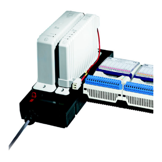
Anhang B CPU Modul 9441 und Power Modul 9444 Gerätelement Beschreibung Power Modul Power Modul 9444 LEDs Status- bzw. Fehleranzeige externe Hilfsenergie und (11) Ausgang Power Modul (12) CPU Modul CPU Modul 9441 (10) (13) LEDs Status- bzw. 11965E00 Fehleranzeige LC-Buchse für Ethernet, Lichtwellenleiter-Anschluss (13) - Page 43 Operating instructions Additional languages r-stahl.com Ethernet CPU module and power module for Zone 1/Class I, Div.1 Series 9441, Series 9444, Series 9492...
- Page 44 Contents General Information ....................3 Manufacturer .......................3 About these Operating Instructions ..............3 Further Documents .....................3 Conformity with Standards and Regulations ............3 Explanation of the Symbols ................4 Symbols in these Operating Instructions ............4 Symbols on the Device ..................4 Safety ........................5 Intended Use .......................5 Personnel Qualification ..................5 Residual Risks ....................6 Transport and Storage ..................8...
-
Page 45: En En
• Data sheet For documents in other languages, see r-stahl.com. Conformity with Standards and Regulations • Certificates and EU Declaration of Conformity: r-stahl.com. • The device has IECEx approval. See IECEx homepage: http://iecex.iec.ch/ to view the certificate. • Further national certificates can be downloaded via the following link: https://r-stahl.com/en/global/support/downloads/. -
Page 46: Explanation Of The Symbols
Explanation of the Symbols Explanation of the Symbols Symbols in these Operating Instructions Symbol Meaning Tip for making work easier DANGER! Dangerous situation which can result in fatal or severe injuries causing permanent damage if the safety measures are not complied with. -
Page 47: Safety
Specialists who perform these tasks must have a level of knowledge that meets applicable national standards and regulations. Additional knowledge is required for tasks in hazardous areas! R. STAHL recommends having a level of knowledge equal to that described in the following standards: •... -
Page 48: 3.3 Residual Risks
(see the "Technical data" chapter). Do not place any load on the device. Check the packaging and the device for damage. Report any damage to R. STAHL immediately. Do not commission a damaged device. Store the device in its original packaging in a dry place (with no condensation), and make sure that it is stable and protected against the effects of vibrations and knocks. - Page 49 Maintain a distance of at least 20 mm between the CPU module, power module and enclosure so that the air circulation is not restricted. Repair work on the device must be performed only by R. STAHL. Gently clean the device with a damp cloth only and without scratching, abrasive or aggressive cleaning agents or solutions.
-
Page 50: 4 Transport And Storage
Transport and Storage 3.3.2 Damage to electrical Components Sensitive electronic components can be damaged by electrostatic discharge (ESD). Before making contact with the device, discharge the charge to an earthed metal body. Avoid direct contact with connectors or the contacts on the module slots. ... - Page 51 Mounting and Installation 5.1.2 Mounting the Socket Operation of the module is only permissible in the following mounting position: Vertical socket, LCD display at the bottom. Screw down the socket directly on an even surface, e.g. on a mounting plate at least 2 mm thick, without distance sleeves.
- Page 52 Mounting and Installation 5.1.3 Mounting the CPU Module and Power Module NOTICE! Malfunction due to damaged fibre optics. Non-compliance can result in material damage. Do not damage the fibre optics on the CPU module. (11) (12) (14) Mounting the CPU module ...
- Page 53 Mounting and Installation 5.1.4 BusRail Mounting DANGER! Explosion hazard due to insufficient discharge or defective rail connection! Non-compliance may result in serious or even fatal injuries. Connect the DIN rail that is in the hazardous area or that is in operation with explosion-protected equipment to the potential equalisation in the explosion-protected area.
- Page 54 Mounting and Installation (17) (18) (19) (19) (20) 12336E00 Plug the DIN rail (17) into the terminal (X5 or X6) and screw it to the mounting plate (tightening torque: 2.6 Nm). Insert the BusRail section (18) into the DIN rail and carefully push it onto the terminal. ...
- Page 55 Mounting and Installation (23) (22) (24) (21) (25) (26) ( 6) 12337E00 Plug the DIN rail piece (21) into the terminal (X5 or X6) and screw it to the mounting plate (tightening torque: 2.6 Nm). Place an end (22) of the connecting cable on the DIN rail and carefully push it onto the terminal.
-
Page 56: 5.2 Replacing And Upgrading The Module
Mounting and Installation Replacing and Upgrading the Module The CPU module and the power module can be safely connected or disconnected during operation in the hazardous area (hot swap), even when live. (11) (12) (14) Replacing the CPU module Disconnect the plug for the fibre optic from the socket. ... -
Page 57: Installation
Mounting and Installation Installation Operation under difficult conditions, in particular on ships, requires additional measures to be taken for correct installation, depending on the operating location. Further information and instructions on this can be obtained from your regional sales contact upon request. 5.3.1 Connect the CPU Module and Power Module The protective caps on the LC plug and LC socket must only be removed immediately before connection, in order to prevent the fibre ends from being contaminated! -
Page 58: Parameterization And Commissioning
Parameterization and Commissioning Parameterization and Commissioning Before commissioning, carry out the following checks: • Mounting and installation of the device according to regulations. • Correct, secure connection of the cables. • No damage to the device or the cables. • The screws are securely fastened to the terminals. Correct tightening torque: 0.5 to 0.6 Nm. - Page 59 Parameterization and Commissioning 6.1.1 Level Overview 12341E00 169128 / 944160310050 Ethernet CPU module and 2020-08-25·BA00·III·en·08 power module for Zone 1/Class I, Div.1 Series 9441, Series 9444, Series 9492...
- Page 60 After the boot process has completed successfully, the LCD display changes to the system level and displays the following information in sequence: LCD display Display/function Module name and manufacturer IS1 Ethernet CPU R. STAHL, Germany 12296E00 Type of coupling, firmware version and boot program version Modbus TCP 20-01 (00-28) 12298E00...
- Page 61 Parameterization and Commissioning System level The current communication addresses of the CPU module and power module are displayed in the system level. Pressing the ◄ or ► buttons moves between the following displays: LCD display Display/function IP address CPU 0-0: IpAdr 192.23.121.7 12299E00 Subnet mask...
- Page 62 Parameterization and Commissioning Information/service level In the information/service level, detailed information about the modules can be displayed and the communication addresses of the CPU module and power module can be changed (see "Display module-dependent information"). Expert level Changes in the expert level have an effect on the functionality of the CPU module and power module! Changes in the expert level must only be made by trained, authorised service staff! Switching to the expert level is password-protected.
- Page 63 Parameterization and Commissioning Changing IP address LCD display Settings Press the [Enter] key twice to switch from the system level to the information/service level. Press the [Enter] key once if the display shows CPU 0-0: Status "CPU 0-0: primary; 9441/12-00-00" in order to switch from the NoDataExch 12309E00 system level to the information/service level.
- Page 64 Parameterization and Commissioning Changing the Subnet mask LCD display Settings Press the [Enter] key twice to switch from the system level to the information/service level. Press the [Enter] key once if the display shows CPU 0-0: Status "CPU 0-0: primary; 9441/12-00-00" in order to switch from the NoDataExch 12309E00 system level to the information/service level.
- Page 65 Parameterization and Commissioning Changing the default gateway The default gateway must be set in order to obtain access to the CPU module from other Ethernet networks. Without a default gateway, the CPU module only answers to telegrams from the system's own network address defined by the IP address and Subnet mask.
- Page 66 Parameterization and Commissioning Setting the port for acyclic HART communication Changes to the port settings can have an effect on the functionality of the socket! Changes to the port settings must only be made by trained, authorised service staff! Before changing the port settings, ensure that the required port is not already in use by other applications in the system.
- Page 67 Parameterization and Commissioning 6.1.3 Redundant Operation – Switching between "Primary" and "Backup" Device component Slot 0-1 CPU 0-1 Slot 0-0 CPU 0-0 Display and keyboard for 0-0 and 0-1 15121E00 Slots 0-0 and 0-1 can, depending on the system status, perform the primary or backup function.
- Page 68 Parameterization and Commissioning Switching between "Primary" and "Backup" LCD display Settings Install the CPU module and power module (see "Mounting and installation" chapter). Boot the system CPU 0-0: (see "Level overview" chapter, "Startup" section). IpAdr; 0.0.0.0 15118E00 CPU 0-0 is the primary and CPU 0-1 is the backup. Only CPU 0-0 can be controlled or parametrised using the display.
- Page 69 Parameterization and Commissioning LCD display Display/function CPU module status CPU 0-0: Status NoDataExch 12309E00 Possible status information: Status information on the Meaning LCD display Hardware error Hardware error detected DataExch CPU module is in data exchange, configuration via DTM NoDataExch CPU module is not in data exchange Config error...
- Page 70 Parameterization and Commissioning 6.1.5 Displaying Information about I/O Modules LCD display Settings Press the [Enter] key to switch from the system level to the CPU 0-0: Status module level. NoDataExch 12309E00 The following display appears (shown on the left). ...
- Page 71 Parameterization and Commissioning LCD display Display/function Display of the firmware and hardware revisions. slot FW 02-04, HW ‘E’ 12269E00 Display of the serial number. slot SNo: 123456-7890 12270E00 Digital output module In addition to the general displays, the digital output module also exhibits the following displays: LCD display Display/function...
- Page 72 Parameterization and Commissioning Analog Output Module/Analog Input Module The menus for the Analog Output Module and Analog Input Module are identical. Additional menu items exist for the AOMH 9461, AOMH 9466 and TIM R 9480 modules (see "Analogue module with HART" and "Temperature Input Module" sections). LCD display Display/function I/O data.
- Page 73 Parameterization and Commissioning 6.1.6 Display Diagnostic Data for the Ethernet Switch LCD display Settings Press the [Enter] key twice to switch from the system level to the CPU 0-0: Status information/service level. NoDataExch 12309E00 The following display appears (shown on the left). ...
- Page 74 Parameterization and Commissioning 6.1.7 Manually backing up Diagnostic Data The diagnostic data is stored in the RAM during operation. The diagnostic data from the RAM is backed up to Flash storage every 24 hours or in the event of a serious error. Backed up diagnostic data is also available after a reset or recommissioning.
-
Page 75: Operation
Operation Operation Operation For device operation, observe the information in the "Intended Use" and "Parameterisation and Commissioning" chapters. Indications The LEDs on the device indicate the operating state of the device (see also the "Device design" chapter). Colour Meaning LINK Green Ethernet status Green CPU operation indication... - Page 76 Operation Error Status Status description/troubleshooting "RUN" LED Data exchange • CPU is exchanging data with AS. lights up with AS • No common module alarms are present. "ERR" LED • Signal alarms may be present. is off These are displayed on the module or on the LCD display.
- Page 77 If the error cannot be eliminated using the specified procedures: Contact R. STAHL Schaltgeräte GmbH. For rapid processing, have the following information ready: • Type and serial number of the device • DCS/PLC •...
-
Page 78: Maintenance, Overhaul, Repair
Only return or package the devices after consulting R. STAHL! Contact the responsible representative from R. STAHL. R. STAHL's customer service is available to handle returns if repair or service is required. Contact customer service personally. Go to the r-stahl.com website. -
Page 79: Cleaning
Accessories and Spare Parts NOTICE! Malfunction or damage to the device due to the use of non-original components. Non-compliance can result in material damage. Use only original accessories and spare parts from R. STAHL Schaltgeräte GmbH (see data sheet). 169128 / 944160310050 Ethernet CPU module and 2020-08-25·BA00·III·en·08... -
Page 80: Annex A
Annex A Annex A 13.1 Technical Data Explosion Protection Version CPU module 9441 Power module 9444 Socket 9492 Global (IECEx) Gas and dust IECEx KEM 08.0035X Ex d [ia Ga] Ex d e [ia Ga] IIC T4 Gb Ex d e [ia Ga] IIC T4 Gb [op is T6 Ga] IIC T4 Gb [Ex ia Da] [Ex op is Da] [Ex ia Da] IIIC... - Page 81 Annex A Technical Data Interfaces Ethernet interface Connection Fibre optic, 100BASE-FX, Ex op is Protocols Modbus TCP Transfer rate max. 100 Mbps Max. line length 2000 m Operator interface Ethernet status "LINK" LED, green Operation of CPU "RUN" LED, green module, power module Error in CPU module, "ERR"...
- Page 82 G3 Mounting / Installation Installation conditions Mounting type On mounting plate Mounting position Vertical For further technical data, see r-stahl.com. Ethernet CPU module and 169128 / 944160310050 power module for Zone 1/Class I, Div.1 2020-08-25·BA00·III·en·08 Series 9441, Series 9444, Series 9492...
-
Page 83: Annex B
Annex B Annex B 14.1 Device Design Socket 9492 (simplex or redundant) Device Description component Slot Slot for vertical BusRail connection (X6) – Reserved Slot Slot for CPU module Slot Slot for power module Slot Slot for horizontal BusRail connection (X5) Mounting holes 4 x mounting holes (14) -
Page 84: 14.2 Dimensions / Fastening Dimensions
Annex B CPU module 9441 and power module 9444 Device Description component Power module Power module 9444 LEDs Status or error indication for external auxiliary power and (11) power module output (12) CPU module CPU module 9441 (10) (13) LEDs Status or error 11965E00 indication for Ethernet,... - Page 86 Class I, DIV 2 / Zone 1 Installation Ethernet CPU Module 9441/12-0*-*0 and Power Module 9444/12-11: for connection to I/O Modules located in with Socket 9492/12-11-** are Explosion-proof modules for Class I, II, III, Division 2, Group A-G, installation in Class I, Division 2, Group A-D or Class I, Zone 1, or Class I, Zone 1, Group IIC/IIB Group IIC/IIB areas;...
- Page 87 Live connection or disconnection of the fibre optic communication link in hazardous location is only permitted when connected to an “op is” limiting device (e.g. R. STAHL types 9721) General Notes see Certification drawing for IS1 resp. IS1+ Remote I/O System No. 9400 6 031 003 1 or 9400 6 031 004 1.
- Page 88 Example for Fieldbus System Topology with Bus Isolators The IS1 resp. IS1+ Remote I/O is a DIN rail mounted system designed interfacing Automation control systems with DIV 1 / Zone 1 to record and output process control signals between hazardous installation of IS1 resp.
- Page 89 Block Diagram of an RS485 Field Station: I.S. Inputs and Outputs Class I, II, III, DIV 1, Groups A-G; Class I, Zone 0, IIC/IIB or Non I.S. or Nonincendive circuits, Class I, II, III, DIV 2, Group A-G; Class I, Zone 2, Group IIC/IIB Block Diagram of an Ethernet Field Station: I.S.
- Page 90 National Electrical Code, ANSI/NFPA 70 Article 500 or Canadian Electrical Code, CSA C22. Installation with the use of an appropriate fieldbus isolator for nonincendive fieldbus circuits (e.g. R. STAHL type 9185). The Ethernet interface is achieved with the use of media converters and switches providing optical Ethernet.
- Page 91 Block Diagram of an RS485 Field Station: I.S. Inputs and Outputs Class I, II, III, DIV 1, Groups A-G; Class I, Zone 0, IIC/IIB or Non I.S. or Nonincendive circuits, Class I, II, III, DIV 2, Group A-G; Class I, Zone 2, Group IIC/IIB Block Diagram of an Ethernet Field Station: I.S.
- Page 92 Fieldbus Isolating Repeater Type 9185/11-35-10 Connections: X3, Pin 3, 5, 6, 8 Terminating resistor Z: value > 143 ohms + 1%, > 400 mW, with a thermal rating of 140 K/W. This resistor is included in the STAHL Entity parameters: Fieldbus connector.
Need help?
Do you have a question about the is1+ 9441 Series and is the answer not in the manual?
Questions and answers