Table of Contents
Advertisement
Ashly Amplifier User Guide
Document: DOC-HW-ASH-UG-B-0
Advanced Simulation Technology inc.
500A Huntmar Park Drive, Herndon, Virginia 20170 USA
Revision B, Version 0 (July, 2019)
Advanced Simulation Technology inc.
500A Huntmar Park Drive
Herndon, Virginia 20170 USA
Tel. (703) 471-2104 • Fax. (703) 471-2108
asti-usa.com
Advertisement
Table of Contents

Related Manuals for Ashly ne8250c


Summary of Contents for Ashly ne8250c
- Page 1 500A Huntmar Park Drive Herndon, Virginia 20170 USA Tel. (703) 471-2104 • Fax. (703) 471-2108 asti-usa.com Ashly Amplifier User Guide Document: DOC-HW-ASH-UG-B-0 Advanced Simulation Technology inc. 500A Huntmar Park Drive, Herndon, Virginia 20170 USA Revision B, Version 0 (July, 2019)
- Page 3 Product Name: Ashly Power Amplifier Ashly Amplifier User Guide © Copyright ASTi 2019 Restricted Rights: Use, duplication, or disclosure by the Government is subject to restrictions as set forth in subparagraph (c)(1)(ii) of the Rights in Technical Data and Computer Software clause at DFARS 252.227-7013.
- Page 4 Revision history Date Revision Version Comments 7/26/2019 Converted content to XML. Updated content for gram- mar, accuracy, and style.
-
Page 5: Table Of Contents
Contents 1.0 Introduction 1.1 Dimensions 2.0 Getting started 2.1 Cooling 2.2 Set up an Ashly Power Amplifier 3.0 General information 3.1 Front indicator lights 3.2 Rear panel connections 3.3 Front panel controls 4.0 Technical specifications 4.1 Wiring 4.2 Minimum guaranteed power 4.3 Reliability... -
Page 7: Introduction
Note: This document only pertains to Ashly Power Amplifiers and ASTi equipment. For gen- eral information about the Ashly Power Amplifier, go to Ashly.com. The Ashly Power Amplifier drives four to eight passive audio loudspeakers. Each amplifier is a network device that integrates with ASTi’s Audio Communications Environment Network (ACENet). -
Page 8: Dimensions
48.26 cm 8.89 cm Table 1: Ashly Power Amplifier dimensions Figure 2, "Ashly Power Amplifier front and rear panels" below shows the Ashly Power Ampli- fier's front and rear panels: Figure 2: Ashly Power Amplifier front and rear panels Copyright © 2019 Advanced Simulation Technology inc. -
Page 9: Getting Started
(2.5cm) away from the amplifier sides, and the back of the rack should be open. 2.2 Set up an Ashly Power Amplifier Figure 3, "Ashly Power Amplifier rear panel" below shows the Ashly Power Amplifier's rear panel: Figure 3: Ashly Power Amplifier rear panel To set up an Ashly Power Amplifier, follow these steps: 1. - Page 10 Ashly Amplifier User Guide (Rev. B, Ver. 0) 4. On the front panel, turn the channel attenuators all the way down. 5. Turn on the Power switch. The power indicator illuminates after a short boot-up sequence. 6. After connecting the amplifier to the network, set up the amplifier on ACENet in the Telestra Remote Management System.
-
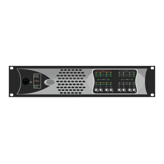
Page 11: General Information
Rear panel connections Front panel controls 3.1 Front indicator lights Figure 4, "Ashly Power Amplifier front indicator lights" below shows the Ashly Power Ampli- fier's front indicator lights: Figure 4: Ashly Power Amplifier front indicator lights 3.2 Rear panel connections... - Page 12 Input connectors: removable Euroblock connectors for balanced analog audio signal input. ASTi system setup does not use the input connectors. Figure 5, "Ashly Power Amplifier rear panel" below shows rear panel connections on the Ashly Power Amplifier: Figure 5: Ashly Power Amplifier rear panel The CAT5 Ethernet cables connect to the DATA LINK 10/100 Mbps port and either the Primary or Secondary Network Digital Audio ports on the rear panel.
-
Page 13: Front Panel Controls
Ashly Amplifier User Guide (Rev. B, Ver. 0) 3.3 Front panel controls Channel Level Controls act as the overall master gain control for each channel. An installation's exact setting depends on a number of factors: Speaker placement Speaker sensitivity The driven space's size The system's sound level Conventional audio setup procedures apply. -
Page 14: Technical Specifications
The Ashly Power Amplifier guarantees the following minimum power: 150 W per channel at 8 ohms 250 W per channel at 4 ohms 4.3 Reliability The Ashly Power Amplifier's (P/N: ne8250c low-Z) typical mean time between failure (MBTF) is 478,000 hours. Copyright © 2019 Advanced Simulation Technology inc. -
Page 15: Appendix A: References
A-1 Ashly Power Amplifier part numbers This document refers to a specific Ashly Power Amplifier. If purchasing an Ashly Power Ampli- fier from another source, follow the part numbers in Table 3, "Ashly Power Amplifier part num- ber" below to ensure compatibility.
Need help?
Do you have a question about the ne8250c and is the answer not in the manual?
Questions and answers