RCbenchmark 1580 Series Assembly Manual
Dynamometer
Hide thumbs
Also See for 1580 Series:
- Assembly manual (4 pages) ,
- General user manual (28 pages) ,
- Assembly manual (4 pages)

Related Manuals for RCbenchmark 1580 Series


Summary of Contents for RCbenchmark 1580 Series
- Page 1 Dynamometer Series 1580/1585 Assembly Manual 1.15 For the latest version of the manual and extra tutorials, please visit RCbenchmark.com...
- Page 3 Install 5kg load cell Wires out on this side 2x M4 Lower structural part Note: for added safety, you may use removable (blue) thread- locking fluid to secure the screws. Do not use permanent (red) fluid.
- Page 4 Wires pointing Install 2kg load cell and inside for both load upper structural part cells Upper structural part 2x 2kg load cell 4x M5 ⚠ 2x M5 Do not tighten yet.
- Page 5 Attach hinges to motor mounting part 4x M4 5mm 2x Hinge Motor mounting part...
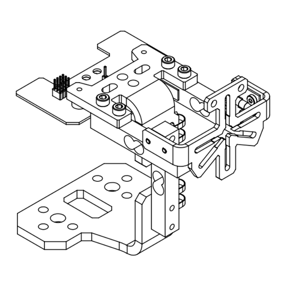
- Page 6 4x M4 5mm Assemble data ⚠ Do not tighten yet acquisition board, motor mounting part, and lower structural part 2x Spacer Data acquisition board 2x M4 Washer 2x M4 12mm...
- Page 7 Position 2kg load cells parallel to each other and tighten Tighten 4x Tighten 4x Parallel Top view...
- Page 8 Connect in the following order: the load cells, the power cables, and the USB cable Positive input (+) *Load cell connector (red wire to orientation is not important power supply) USB cable Ground input (-) (black wire to power supply) 3x Connect load cells under circuit* Secure the 3 wires...
-
Page 9: Software Installation
Software installation 1) Go to docs.rcbenchmark.com/en/dynamometer/ software/dynamometer-software-download.html to install the app. 2) Launch the application from your computer. 3) Connect the device to a computer using the USB cable. 4) Press the "Connect" button in the app as seen below. - Page 10 Calibration Follow the instructions provided in the app to calibrate your device. Recalibrate the device if it has been disassembled, if the wires have been moved, or every 2 months. 1) Go to the "Utilities" tab. 2) Calibrate the thrust. 3) Calibrate the torque and the weight.
- Page 11 Power system schematic RPM probe Ohmmeter (tap into motor signal) (before use, disconnect motor Motor from ESC Battery/power supply MAX. 35V RPM PROBE ESC signal (PWM) To computer The servo power rail of the Series 1580 in not connected. It is USB powered (max 100 mA) by a jumper on the Series 1585.
- Page 12 Secure all wires, the ESC, and the device Dangling wires may cause errors in the thrust and torque measurements. Secure all wires and the ESC using tie-wraps or double-sided tape. Wires from the motor to the ESC may be secured along the load cells. If the motor has stiff wires, it is recommended to perform a torque calibration for high precision measurements.
- Page 13 Attach using tie-wraps or double-sided tape ESC signal Insert or solder RPM probe in connector ESC - ESC + 2x C-clamp for attaching to Do not table reverse polarity...
-
Page 14: Speed Measurement
Support and warranty For feedback of questions regarding the installation of the device, please contact us at support@rcbenchmark.com. RCbenchmark products are fully tested and inspected before shipping. This product is covered by a one year warranty on manufacturing defects. The warranty does not cover misuse, product modifications, and... - Page 15 Motor and propeller testing The mechanical load on the motor is controlled by changing the throttle and by installing a propeller of different size or pitch. You may also perform your tests at multiple voltages. You can manually control the motor for your tests and record your data manually or continuously.
- Page 16 Included -Assembly manual (1) -RPM probes (1 + 1 extra) -Data acquisition board (1) -Calibration bar (1) -Spacers (2) -Calibration weight (200g) -Black knobs (2) -Motor mounting part (1) -Washers M4 (2) -Lower structural part (1) -Upper structural part (1) -Power cables (2 x 75cm) -M4 5mm (12) -Load cell 2 kg (2)
Need help?
Do you have a question about the 1580 Series and is the answer not in the manual?
Questions and answers