Table of Contents

Related Manuals for Autonics VG-C04 -25E Series


Summary of Contents for Autonics VG-C04 -25E Series
- Page 1 User Manual Vision Sensors VG Series Thank you for purchasing an Autonics product. This user manual contains information about the product and its proper use, and should be kept in a place where it will be easy to access. www.autonics.com...
- Page 2 © Copyright Reserved Autonics Co., Ltd.
-
Page 3: Preface
Preface Preface Thank you for purchasing an Autonics product. This user manual contains information about the product and its proper use, and should be kept in a place where it will be easy to access. © Copyright Reserved Autonics Co., Ltd. -
Page 4: User Manual Guide
(www.autonics.com) to download a copy. The manual's content may vary depending on changes to the product's software and other unforeseen developments within Autonics, and is subject to change without prior notice. Upgrade notice is provided through our homepage. ... -
Page 5: User Manual Symbols
Failure to follow instructions can result in serious injury or death. Failure to follow instructions can lead to a minor injury or product damage. An example of the concerned feature's use. Annotation mark. ※1 © Copyright Reserved Autonics Co., Ltd. -
Page 6: Safety Considerations
Failure to follow this instruction may result in fire or product damage. The above specifications are subject to change and some models may be discontinued without notice. Be sure to follow cautions written in the instruction manual, user manual and the technical descriptions (catalog, homepage). © Copyright Reserved Autonics Co., Ltd. -
Page 7: Caution During Use
Do not use the product in the place where strong magnetic field or electric noise is generated. This unit may be used in the following environments. ① Indoor (in the environment conditions in specifications) ② Altitude max. 2,000m ③ Pollution degree 2 ④ Installation category Ⅱ © Copyright Reserved Autonics Co., Ltd. - Page 8 Caution during Use viii © Copyright Reserved Autonics Co., Ltd.
-
Page 9: Table Of Contents
5.4.1 Replacement of color filter or polarizing filter ..........30 5.4.2 Replacement of light .................. 31 Vision Sensor Program [Vision Master] ..........33 Overview ......................33 Vision Master Work Flow ................... 37 6.2.1 Setting mode ....................37 © Copyright Reserved Autonics Co., Ltd. -
Page 10: Table Of Contents
6.7.10 Object counting ..................105 6.7.11 Color identification ..................108 6.7.12 Area of color ....................111 6.7.13 Object of color counting................114 Settings ....................117 Simulator ......................118 Device (Vision Sensor) ..................121 Troubleshooting ..................125 © Copyright Reserved Autonics Co., Ltd. -
Page 11: Product Instruction
Applicable to various environment with various light and filter - 4 types of light (white/red/green/blue) - 4 types of color filter (red/green/blue/infrared blocking) - Polarizing filter (window/red/green/blue/infrared blocking) Protection structure IP67 (IEC standard) © Copyright Reserved Autonics Co., Ltd. -
Page 12: Accessory And Sold Separately
1 Product Instruction Accessory and sold separately Overall configuration diagram 1.2.1 © Copyright Reserved Autonics Co., Ltd. -
Page 13: Accessory
Before using the product, please check whether all accessories above are included. If there is a damaged or missing accessory, please contact Autonics sales team or retailer. Please refer to the model name below, when purchasing the lost accessory. -
Page 14: Sold Separately
Polarizing filter FL-P-VG FL-RP-VG FL-GP-VG FL-BP-VG FL-ICP-VG (window) (red) (green) (blue) (infrared blocking) Power I/O cable CID-2-VG (length: 2m) CLD-2-VG (length: 2m) CID-5-VG (length: 5m) CLD-5-VG (length: 5m) CID-10-VG (length:10m) CLD-10-VG (length:10m) © Copyright Reserved Autonics Co., Ltd. - Page 15 CLR-10-VG (length:10m) Bracket B Protection cover ※ ■ ■ P96-M12-1 BK-VG-B ※Protection cover protects unused connectors from foreign substances. When installing the protection cover, please tighten the cover with hand. Vision panel ■ APC-1011 © Copyright Reserved Autonics Co., Ltd.
-
Page 16: Ordering Information
② Type Mono CMOS ③ Image element Color CMOS ④ Resolution (pixel) 752×480 White ⑤ Light Green Blue 16mm ⑥ Effective focal length 25mm Ethernet (TCP/IP) ⑦ Communication ※1. Light can be purchased separately. © Copyright Reserved Autonics Co., Ltd. -
Page 17: Unit Description
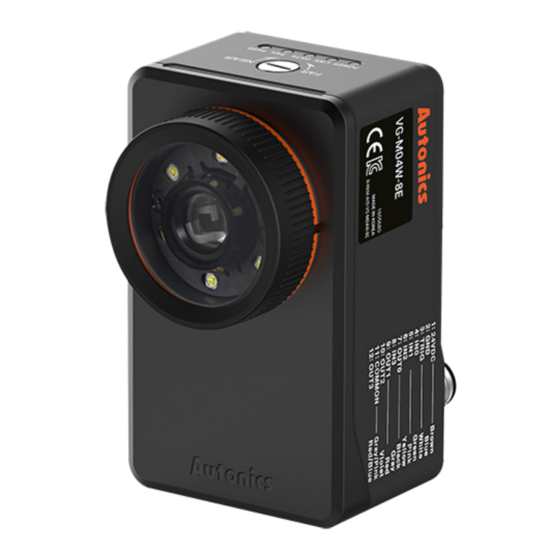
DATA Orange LED indicator vision sensor to PC. Flashes when detects failure during work FAIL Failure indicator Red LED group inspection. Flashes when passed inspection during PASS Pass indicator Green LED work group inspection. © Copyright Reserved Autonics Co., Ltd. - Page 18 1 Product Instruction © Copyright Reserved Autonics Co., Ltd.
-
Page 19: Specifications
Control output (OUT0 to OUT3) Output Type : inspection completion, inspection result, external light trigger, alarm, camera busy, changing work group completed FTP transmission Possible Communication Ethernet(TCP/IP), 100BASE-TX/10BASE-T Protection circuit Output short over current protection circuit © Copyright Reserved Autonics Co., Ltd. - Page 20 ※2. These inspections identify data by converting the color image to the mono image. ※3. Environment resistance is rated at no freezing or condensation. ※4. The weight includes packaging. The weight in parenthesis is for unit only. © Copyright Reserved Autonics Co., Ltd.
-
Page 21: Dimensions
3 Dimensions Dimensions Body (unit: mm) Bracket Bracket B (BK-VG-B) Bracket A (BK-VG-A) 3.2.2 3.2.1 © Copyright Reserved Autonics Co., Ltd. -
Page 22: Cable
(1) CID Series (2) CLD Series ※L(m): 2m, 5m, 10m Please refer to the cable length. Ethernet cable 3.3.2 (1) CIR Series (2) CLR Series ※ L(m): 2m, 5m, 10m Please refer to the cable length. © Copyright Reserved Autonics Co., Ltd. -
Page 23: Connections
4 Connections Connections ※ Use the product which of power supply is 24VDC. When selecting a product, please refer to Autonics selection guide. © Copyright Reserved Autonics Co., Ltd. -
Page 24: Power I/O Cable (M12 12-Pin Connector)
Gray - Down counter change Bit 3 - Quadrature B Gray/Pink COMMON COMMON Black OUT0 Inspection completion, inspection result, OUT1 external light trigger, alarm, camera busy, Purple OUT2 changing work group completed Red/Blue OUT3 © Copyright Reserved Autonics Co., Ltd. -
Page 25: Input
(1) External trigger input (TRIG), Work group change input (IN0 to IN3) Alarm cleared (IN0 to IN3) (2) Encoder input (IN2, IN3) Output (OUT0 to OUT3) 4.1.2 (1) NPN open collector output (2) PNP open collector output © Copyright Reserved Autonics Co., Ltd. -
Page 26: Ethernet Cable (M12 8-Pin/Rj45 Connector)
4 Connections Ethernet Cable (M12 8-pin/RJ45 connector) M12 8-pin RJ45 Pin arrangement Cable color Pin No. Signal Pin No. Signal White/Orange Orange White/Green Green White/Blue Blue White/Brown Brown © Copyright Reserved Autonics Co., Ltd. -
Page 27: Installation
- Setting network from Vision Master Adjusting vision sensor focus 6.6.2 Camera - Running Vision Master and activating the 5.3 Focus Adjustment 'Focusing Guide' function in the camera setting menu - Adjusting focus with focus adjuster © Copyright Reserved Autonics Co., Ltd. -
Page 28: Working Distance And Fov By Effective Focal Length
Working focal 1,000 distance length Horizontal axis (H) Vertical axis (V) ㅡ Horizontal 16mm ㅡ axis (H) Vertical ㅡ axis (V) ㅡ ㅡ Horizontal 25mm ㅡ ㅡ axis (H) Vertical ㅡ ㅡ axis (V) © Copyright Reserved Autonics Co., Ltd. -
Page 29: Installation Of Vision Sensor
Using (-) screwdriver, turn focus adjuster to right and left to adjust the focus. ※Please refer to '6.3 Installation of Vision Master' for the installation of Vision Master and network setting. ※Please refer to '6.6.2 Camera (6) Focusing guide ' for the focusing guide. © Copyright Reserved Autonics Co., Ltd. -
Page 30: Replacement Of Light And Filter
2nd While fixing the vision sensor with the assembly tool, hold the lens cover and disassemble it in a counter clock wise direction. 3rd Instead of the disassembled lens cover, assemble another color filter or polarizing filter in clock wise direction. © Copyright Reserved Autonics Co., Ltd. -
Page 31: Replacement Of Light
3rd Disassemble the light cover using the (+) screwdriver, and disassemble the inner LED light. 4th Place the connection pin of PCB of the inner LED light to face the direction of 6 o’clock and assemble it to the vision sensor body. © Copyright Reserved Autonics Co., Ltd. - Page 32 5th Align the light cover with the groove in the direction of 12o’clock and fix it with the screw. Tighten them with the 1.2kgf∙cm of tightening torque. 6th Assemble the disassembled lens cover in clock wise direction. © Copyright Reserved Autonics Co., Ltd.
-
Page 33: Vision Sensor Program [Vision Master]
6 Vision Sensor Program [Vision Master] Vision Sensor Program [Vision Master] Overview Vision Master is the vision sensor program that is connected with VG Series, Autonics vision sensor, to utilize it. Vision Master provides graphic user interface to make setting parameter and managing monitoring data of vision sensor easy. - Page 34 Inspects the ROI area of the input image based on the ROI area of the image registered by user. <Pass> <Template> <Fail> Area Inspects the direction of the edge in the input image based on the edge registered by user in the same area. <Template> <Pass> <Fail> Edge © Copyright Reserved Autonics Co., Ltd.
- Page 35 Inspects the input image based on the angle between two edges registered by user. <Template> <Pass> <Fail> Angle Inspects the input image based on the area between two circles registered by user. <Template> <Pass> <Fail> Diameter © Copyright Reserved Autonics Co., Ltd.
- Page 36 Compares the number of objects in a certain color which are in the ROI of registered image and that of the input image. <Template> <Pass> <Fail> Object of color counting ※Color identification, area of color, and object of color counting are only for VG-C Series. © Copyright Reserved Autonics Co., Ltd.
-
Page 37: Vision Master Work Flow
6 Vision Sensor Program [Vision Master] Vision Master Work Flow Setting mode 6.2.1 © Copyright Reserved Autonics Co., Ltd. -
Page 38: Operation Mode
6 Vision Sensor Program [Vision Master] Operation mode 6.2.2 © Copyright Reserved Autonics Co., Ltd. -
Page 39: Installation Of Vision Master
RJ45 Ethernet port Installation of the program 6.3.2 1st Download Vision Master program at Autonics web page(www.autonics.com). 2nd Close all programs before you start Vision Master installation. Double-click Vision Master setup.exe to start installation. 3rd When Installer Language window appears, select the language and click [OK] button. - Page 40 Please read the articles thoroughly before click [I Agree] button. 6th Choose Install Location window appears. Default installation path is as follows. C:\Program Files (x86)\Autonics\Vision Master\ Click [OK] button to install the program in the default installation path. © Copyright Reserved Autonics Co., Ltd.
- Page 41 If you want to install the program in another installation path, click [Browse..] button to designate a folder you want to install in and click [OK] button. 8th Installation progress is displayed in the status window as follows. © Copyright Reserved Autonics Co., Ltd.
- Page 42 If the check box in the Installation Complete window is checked, Vision Master runs upon completion of installation. You can run Vision Master by double-clicking the Vision Master icon on the desktop. The initial screen displays as follows. © Copyright Reserved Autonics Co., Ltd.
-
Page 43: Installation Folder Structure
6.3.3 This section explains the folder structure created when you installed Vision Master. The Vision Master folder is created in [C:\Program Files (x86)\Autonics\] as a subfolder unless you select a new destination to change location of Vision Master folder. After Vision Master is installed completely, Vision Master installation folder and related folders are created as follows in [C:\Users\(Account name)\Documents\Autonics\] as subfolders and work groups and documents are saved in. -
Page 44: Network Setting
You can check connectable devices and connected devices using Refresh icon ( ) on the top of the window. Factory default of the device (vision sensor) is as follows. IP address 192.168.0.2 Subnet mask 255.255.255.0 Gateway 192.168.0.1 © Copyright Reserved Autonics Co., Ltd. - Page 45 A list of the currently connected vision sensor is displayed. After checking “connectable status” indicator, and connect a vision sensor. : Connectable : Unconnectable - The vision sensor is not connectable because it is connected to another PC already. © Copyright Reserved Autonics Co., Ltd.
- Page 46 If a device is not recognized while it is connected, click “Manual IP Address Searching” and search IP address of the device to connect. (This is usable only when Gateway of the device and PC are same.) © Copyright Reserved Autonics Co., Ltd.
-
Page 47: Start And Exit
Click [X] button on the top right corner of the screen or ‘exit’ in the file menu to end the program. Since work group, parameter settings, and data are not saved automatically, please make sure that you have saved the work group before you exit. © Copyright Reserved Autonics Co., Ltd. -
Page 48: Vision Master Screen Layout
- Operation mode: displays taken images according to the “View Result Image” settings. Please refer to '6.6.6 Inspection'. Inspection Displays inspection result (Pass/Fail) of work group. result © Copyright Reserved Autonics Co., Ltd. - Page 49 - Work group status: displays status of currently registered work group. Parameter Displays specific parameters in the setting menu. Image Displays brightness value and pixel coordinate of the point where the information mouse cursor is pointing on the image window. © Copyright Reserved Autonics Co., Ltd.
-
Page 50: Menu
Load Work Group from PC: Loads work group from the local disk of PC. Work groups are saved in the default folder [C:\Users\ (Account name) \Documents\Autonics\Vision Master\Work] or the folder designated by user. Save Work Group to PC: Saves work groups registered and set in Vision Master to the ... - Page 51 At that moment, selected work group can be set as operating work group when the device turns on. Work group can be registered and saved up to 32. Exit: Exits Vision Master. © Copyright Reserved Autonics Co., Ltd.
- Page 52 User Manual: Loads user manual. Language: Changes program language. Vision Master Update: Updates version of Vision Master. Vision Master Information: Displays information about version of Vision Master and device firmware. © Copyright Reserved Autonics Co., Ltd.
-
Page 53: Toolbar
Takes an image with the camera of vision sensor. ※1, ※2 Takes multiple images with the camera of vision sensor, Continuous Snap according to the set number of frame per second (fps). Backward Loads previous image from images in preview window. © Copyright Reserved Autonics Co., Ltd. - Page 54 ※2. It is displayed only when the camera trigger mode is set to ‘free-run trigger’ or ‘internal trigger’. ※3. Use Multi View function as flows. 1st Click Multi View icon ( ) to open Multi View window as flows. © Copyright Reserved Autonics Co., Ltd.
- Page 55 You can only select devices which of the connectable status indicator is turned on in green color. 4th Set View Result Image. Inspection result of the running device (vision sensor) is displayed in the image window. © Copyright Reserved Autonics Co., Ltd.
- Page 56 6 Vision Sensor Program [Vision Master] 5th You can monitor statistics of Pass/Fail result. 6th You can monitor inspection status of maximum 4 vision sensors at the same time. © Copyright Reserved Autonics Co., Ltd.
-
Page 57: Setting Menu
Setting: Changes IP address setting of the currently connected device. [Current Network Setting] is network information of the currently connected device. To change network setting, enter new information in [New Network Setting]. © Copyright Reserved Autonics Co., Ltd. - Page 58 You can see the list of folder in the server. File Name: Sets file name of image to transmit to the FTP server. Click ‘Image File Naming Rule’ icon ( ) on the right side to set name. © Copyright Reserved Autonics Co., Ltd.
- Page 59 Work Group Number / Work Group Name: Displays number and name of inspecting work group. Image format filename extension: It is image format filename extension. It displays BMP (*.bmp) or JPG (*.jpg). © Copyright Reserved Autonics Co., Ltd.
-
Page 60: Camera
Internal Trigger: Takes image by occurring trigger in the sensor (1 to 60fps) External Trigger: Takes image with external input signal as trigger. If you use external trigger mode, you can use trigger delay mode. © Copyright Reserved Autonics Co., Ltd. - Page 61 ) and enter moving distance and distance resolution of encoder to calculate pulse value according to um/pulse or pulse/um setting value. After setting the trigger delay mode, timing diagram of trigger input is shown as follows. © Copyright Reserved Autonics Co., Ltd.
- Page 62 It is adjusting gain of CMOS image sensor. As higher gain level makes image brighter, increased noises makes resolution low. Setting range is from the level 1 to 16. Gain 1 level Gain 8 level Gain 16 level © Copyright Reserved Autonics Co., Ltd.
- Page 63 When sensing target is in near Focus adjusting is finished. When sensing object is far → rotate to the NEAR → rotate to the FAR direction. direction. © Copyright Reserved Autonics Co., Ltd.
- Page 64 With the higher edge threshold value, edge of high contrast is detected, and with the lower edge threshold value, edge of low contrast can be also detected. Actual Distance: It is for entering actual distance between two edges in unit of ㎛. © Copyright Reserved Autonics Co., Ltd.
- Page 65 After selecting focal length and entering the working distance, click ‘OK’ ( ) in the right bottom corner to register values after calculating distance per 1 pixel into unit of ㎛ based on the working distance and FOV by effective focal length. © Copyright Reserved Autonics Co., Ltd.
-
Page 66: Input
(2) Active level According to the active level, trigger is applied at High or Low. To avoid chattering of trigger signal, the vision sensor starts taking an image when the signal is maintained for 1ms. © Copyright Reserved Autonics Co., Ltd. - Page 67 High High Work group 5 High Work group 6 High High Work group 7 High High Work group 8 High High High … … … … … Work group 16 High High High High © Copyright Reserved Autonics Co., Ltd.
- Page 68 When changing work group of the vision sensor to work group 6 with the serial input signal, input the data signal as follows. Data Clock Input Bit 0 Bit 1 Bit 2 Bit 3 Bit 4 Bit 5 Bit 6 Bit 7 Work group Work group 6 © Copyright Reserved Autonics Co., Ltd.
- Page 69 Quadrature A/Quadrature B (IN2, IN3) Input 2 and input 3 are operated in encoder Quadrature. Both rising edge and falling edge of two encoders are counted. © Copyright Reserved Autonics Co., Ltd.
- Page 70 You can use the alarm cleared input to cleare alarm which is set in the output menu, when alarm is ON. Although alarm is cleared, alarm occures again in the status at alarm condition which is set in the output menu, © Copyright Reserved Autonics Co., Ltd.
-
Page 71: Output
Please refer to '6.6.5 Work Group'. External light trigger: When connected with the external light, power of the external light is turned ON/OFF with output signal from the vision sensor which is synchronized with camera trigger input. © Copyright Reserved Autonics Co., Ltd. - Page 72 Changing work group completed: It is signal to notice that changing work group is completed after inputting work group change input. (2) Control output You can set control output to NPN/PNP and N.O.(Normally open) / N.C(Normally close). © Copyright Reserved Autonics Co., Ltd.
- Page 73 Delay type is the moment of applying output delay time to. You can set whether to delay output after inspection completed or to delay output after trigger input. Delay output after inspection completed Delay output after trigger input © Copyright Reserved Autonics Co., Ltd.
- Page 74 Delay time is the time period of delaying inspection result output for, after starting of output delay operation. Setting range when delay type is “After inspection completed”: 0 to 60,000ms Setting range when delay type is “After trigger input”: 17 to 60,000ms © Copyright Reserved Autonics Co., Ltd.
-
Page 75: Work Group
Add: You can register work to inspect. Select inspection type and register. When making new work group and adding work, an image in the image window is registered ads master image. Please refer to '6.7 Inspection ' for inspection item setting. © Copyright Reserved Autonics Co., Ltd. - Page 76 2nd Press Ctrl+V key to open the message pop-up as below, and click ‘OK’. 3rd The work is copied. 4th Select the copy of the work and click ‘Edit’ to change specific settings of the work. © Copyright Reserved Autonics Co., Ltd.
- Page 77 Alignment: When inspection items with alignment are passed, the vision sensor outputs output signal. Logic combination: You can set output conditions by setting each logic combination to pass or fail with logical operator. © Copyright Reserved Autonics Co., Ltd.
- Page 78 Delete logical operator. Add logical operator: You can add logical operator (AND/OR). Add work/Delete work: You can add registered work to logical output or delete work from logical output. © Copyright Reserved Autonics Co., Ltd.
-
Page 79: Inspection
Sets whether to save inspection result image. Image format Selects image format to save in. (BMP, PNG, JPG) Selects saved path in which result images are saved. Saved path Click on the right to select saved path. © Copyright Reserved Autonics Co., Ltd. - Page 80 Select operation mode: It is to set operation when starting inspection. You can select whether to save or not to save before starting inspection. When the device is turned off, you can lose unsaved data. Setting of displaying the inspection image in full screen © Copyright Reserved Autonics Co., Ltd.
- Page 81 When operating device inspection with calibration function, result value of the ‘edge’, ‘length’, and ‘diameter’ inspections are displayed as actual value in the unit of mm, not pixel. Inspection result value without calibration function Inspection result value with calibration function © Copyright Reserved Autonics Co., Ltd.
-
Page 82: Inspection
To count the number of the object Color identification To inspect average color of the object Area of color To inspect area in a certain color Object of color counting To count the number of objects in a certain color © Copyright Reserved Autonics Co., Ltd. -
Page 83: Alignment
(±°) Automatic It operates teaching automatically, when user changes parameter or teaching adjust ROI. After setting ROI ( ), set area ( ) to inspect ROI ROI type in it. © Copyright Reserved Autonics Co., Ltd. - Page 84 ※Threshold is the boundary value when a value is discontinuously changed. ※1. When set template of ROI is 50% similar with the input image in 50 similarity threshold, the vision sensor regards them as the same target and outputs output signal. © Copyright Reserved Autonics Co., Ltd.
- Page 85 6 Vision Sensor Program [Vision Master] Examples of pass/fail in the alignment inspection Registering template of inspection target (similarity: 100% / similarity threshold: 80%) Passed alignment inspection. Failed alignment inspection. © Copyright Reserved Autonics Co., Ltd.
- Page 86 X: moving X axis coordinate / Y: moving Y axis coordinate / R: angle Examples of pass/fail when inspecting multiple work including alignment Registering template of the inspection target (registering alignment) Applying alignment Unapplying alignment © Copyright Reserved Autonics Co., Ltd.
-
Page 87: Brightness
Even if user set the pass range, it teaches pass range based on mean Automatic teaching brightness of ROI. It sets type of ROI to inspect. ROI type (rectangle/polygon/circle/concentric circle) OK/Cancel It registers work to work group or cancel to register. © Copyright Reserved Autonics Co., Ltd. - Page 88 Registering template of the inspection target (mean brightness: 181 / pass range: 166 to 196) Passed brightness (alignment applied) Failed brightness (Reduced ROI area brightness) (Below mean brightness of ROI area) © Copyright Reserved Autonics Co., Ltd.
-
Page 89: Contrast
Even if user set the pass range, it teaches pass range based on the teaching average contrast value of ROI. It sets type of ROI to inspect. ROI type (rectangle/polygon/circle) OK/Cancel It registers work to work group or cancel to register. © Copyright Reserved Autonics Co., Ltd. - Page 90 6 Vision Sensor Program [Vision Master] Examples of pass/fail in the contrast inspection Registering template of the inspection target (contrast: 74 / pass range: 59 to 89) Passed contrast (alignment applied) Failed contrast © Copyright Reserved Autonics Co., Ltd.
-
Page 91: Area
Dark object on the bright Bright object on the dark Item background background Extracting darker area Extracting brighter area Descrip compared to the brightness compared to the brightness tion standard standard Extraction mode Image © Copyright Reserved Autonics Co., Ltd. - Page 92 ※Threshold is the boundary value when a value is discontinuously changed. Examples of pass/fail in the area inspection Registering template of the inspection target (area: 13229 / pass range: 11244 to 15213) Passed area inspection Failed area inspection © Copyright Reserved Autonics Co., Ltd.
-
Page 93: Edge
It is range of the distance between edge at ROI teaching and edge detected from inspection target. Position threshold If the distance between edge at ROI teaching (0) and edge detected from inspection target is within the range of position threshold, it is processed as pass. © Copyright Reserved Autonics Co., Ltd. - Page 94 X, Y axes coordinate of the edge (A) and distance from the edge (D) are displayed. ROI type OK/Cancel It registers work to work group or cancel to register. ※Threshold is the boundary value when a value is discontinuously changed. © Copyright Reserved Autonics Co., Ltd.
- Page 95 6 Vision Sensor Program [Vision Master] Examples of pass/fail in the edge inspection Registering template of the inspection target (edge angle: 42° / pass range: ±10°) Passed edge (alignment applied) Failed edge © Copyright Reserved Autonics Co., Ltd.
-
Page 96: Shape Comparison
Even if user set the pass range, it teaches pass range based on the teaching pixel of ROI. It sets type of ROI to inspect. ROI type (rectangle/polygon/circle) OK/Cancel It registers work to work group or cancel to register. © Copyright Reserved Autonics Co., Ltd. - Page 97 Examples of pass/fail in the shape comparison inspection Registering template of the inspection target (Similarity: 100% / Similarity threshold: 80%) Passed shape comparison inspection (alignment applied) Failed shape comparison inspection © Copyright Reserved Autonics Co., Ltd.
-
Page 98: Length
ROI type and firstly detected edge becomes standard for inspection. (two arrows) OK/Cancel It registers work to work group or cancel to register. ※Threshold is the boundary value when a value is discontinuously changed. © Copyright Reserved Autonics Co., Ltd. - Page 99 6 Vision Sensor Program [Vision Master] Examples of pass/fail in the length inspection Registering template of the inspection target (Length: 386 / pass range: 376 to 396) Passed length inspection (alignment applied) Failed length inspection © Copyright Reserved Autonics Co., Ltd.
-
Page 100: Angle
ROI type and firstly detected edge becomes standard for inspection. (two arrows) OK/Cancel It registers work to work group or cancel to register. ※Threshold is the boundary value when a value is discontinuously changed. © Copyright Reserved Autonics Co., Ltd. - Page 101 6 Vision Sensor Program [Vision Master] Examples of pass/fail in the angle inspection Registering template of the inspection target (angle: 98° / pass range: 88 to 108°) Passed angle inspection Failed angle inspection © Copyright Reserved Autonics Co., Ltd.
-
Page 102: Diameter
It is roundness of the detected circle. It sets threshold to detect circle. Roundness It inspects diameter of the circle which of roundness is over the threshold. ※ 1 threshold checks whether to use roundness threshold or not. © Copyright Reserved Autonics Co., Ltd. - Page 103 It registers work to work group or cancel to register. ※Threshold is the boundary value when a value is discontinuously changed. ※1. When roundness threshold is set to 50, an object with 50% of circle shape is regarded as circle. © Copyright Reserved Autonics Co., Ltd.
- Page 104 6 Vision Sensor Program [Vision Master] Examples of pass/fail in the diameter inspection Registering template of the inspection target (diameter: 92, / pass range: 75 to 111) Passed diameter inspection Failed diameter inspection © Copyright Reserved Autonics Co., Ltd.
-
Page 105: Object Counting
It sets the standard value for regarding as an area. Area filter Area filter threshold regards a group of objects with the number of pixels threshold over the binary threshold as an area. © Copyright Reserved Autonics Co., Ltd. - Page 106 When user changes parameter or adjust ROI, it teaches automatically. teaching It sets type of ROI to inspect. ROI type (rectangle/polygon/circle) OK/Cancel It registers work to work group or cancel to register. ※Threshold is the boundary value when a value is discontinuously changed. © Copyright Reserved Autonics Co., Ltd.
- Page 107 Examples of pass/fail in the object counting inspection Registering template of the inspection target (the number of object: 4 / pass range: 4) Passed object counting (alignment applied) Failed object counting © Copyright Reserved Autonics Co., Ltd.
-
Page 108: Color Identification
(color area) mode. (RGB/CIElab/HSV) ROI average Item Description color R (Red) / G (Green) / B (Blue) L: contrast (+white ↔ -black) CIELab a: Saturation (+red ↔ -green) b: Saturation (+yellow ↔ -blue) © Copyright Reserved Autonics Co., Ltd. - Page 109 Color within the deviation range which is from b: Pass range for blue “A” to “a” is regarded as Pass. Color within the deviation range from “A” to setting value of each color is regarded as Pass. © Copyright Reserved Autonics Co., Ltd.
- Page 110 6 Vision Sensor Program [Vision Master] Examples of pass/fail in the color identification inspection Registering template of the inspection target Passed color identification Failed color identification © Copyright Reserved Autonics Co., Ltd.
-
Page 111: Area Of Color
ROI average color. green, blue color. It displays average color of ROI in a data value, depends on the set color system (color area) mode. ROI average color (RGB/CIElab/HSV) Item Description © Copyright Reserved Autonics Co., Ltd. - Page 112 Color within the deviation range which is from b: Pass range for blue “A” to “a” is regarded as Pass. Color within the deviation range from “A” to setting value of each color is regarded as Pass. © Copyright Reserved Autonics Co., Ltd.
- Page 113 Examples of pass/fail in the area of color inspection Registering template of the inspection target (area of color: 1948 / pass range: 1655 to 2240) Passed area of color Failed area of color © Copyright Reserved Autonics Co., Ltd.
-
Page 114: Object Of Color Counting
ROI average color. green, blue color. It displays average color of ROI in a data value, depends on the set color system (color area) mode. ROI average color (RGB/CIElab/HSV) © Copyright Reserved Autonics Co., Ltd. - Page 115 Color within the deviation range which is from b: Pass range for blue “A” to “a” is regarded as Pass. Color within the deviation range from “A” to setting value of each color is regarded as Pass. © Copyright Reserved Autonics Co., Ltd.
- Page 116 Examples of pass/fail in the object of color counting inspection Registering template of the inspection target (the number of object: 10 / pass range: 10 Passed object of color counting Failed object of color counting © Copyright Reserved Autonics Co., Ltd.
-
Page 117: Settings
A list of connected vision sensors is displayed. You can select the vision sensor to use from the list of connected vision sensor. After registering work group and setting parameters, you can start inspection. Device (Vision sensor) © Copyright Reserved Autonics Co., Ltd. -
Page 118: Simulator
2nd Click ‘Open image(O)’ or ‘Open all images from folder(F)’ from the File(F) in the menu to load an image to inspect. You can see the loaded image in the image window and preview window in the right side of the screen. Work group © Copyright Reserved Autonics Co., Ltd. - Page 119 3rd When adding work in the ‘work group’ setting, click [OK] button in the following pop-up message to register master image. For more details, refer to '6.6.5 Work Group'. 4th Set inspection items. For more details, refer to '6.7 Inspection'. Work group © Copyright Reserved Autonics Co., Ltd.
- Page 120 ) on the top right side. You can see inspection status in the ‘Inspection’ setting window by playing the images of the preview window. Inspection 6th You can save work group registered with the simulator in the PC. © Copyright Reserved Autonics Co., Ltd.
-
Page 121: Device (Vision Sensor)
2nd Click focusing guide in the ‘Camera’ setting to set the area to focus on, and adjust focus with focus adjuster. When adjusting focus with focusing guide, run Continuous snap ( Camera 3rd If taken images are dark, set the exposure time longer or light level and gain higher. Camera © Copyright Reserved Autonics Co., Ltd. - Page 122 4th Select the type of input signal which performs as a camera shutter to take image by setting the trigger mode. Camera 5th Set input and output. Input Output 6th Add work in the ‘work group’ setting. For more details, refer to '6.6.5 Work Group'. Work group © Copyright Reserved Autonics Co., Ltd.
- Page 123 You can see the images which is being taken by the vision sensor. 9th When you click Start device inspection, Select operation mode window appears. Select between Save and run and Unsave and run for registered work group. Inspection © Copyright Reserved Autonics Co., Ltd.
- Page 124 7 Settings You can also save work group in the File menu to start inspection. 10th Monitor inspection status. Inspection © Copyright Reserved Autonics Co., Ltd.
-
Page 125: Troubleshooting
Error occurs in Ethernet Refer to ‘6.3.5 Network setting' to set correctly. communication. Check that connection or specification of the communication cable is corresponding to that of Autonics guide. Use the Autonics cable (sold separately). © Copyright Reserved Autonics Co., Ltd. - Page 126 * Dimensions or specifications on this manual are subject to change and some models may be discontinued without notice. MSO-VGU1-V4.0-1901US...
Need help?
Do you have a question about the VG-C04 -25E Series and is the answer not in the manual?
Questions and answers