
Related Manuals for Toa IP-1000AF


Summary of Contents for Toa IP-1000AF
- Page 1 User’s Manual IP Audio Interface Unit IP-1000AF Thanks for your purchase of TOA products IP-1000 series. Please read the manual carefully to ensure the machine operating in long time and fault-free. TOA Corporation...
- Page 2 Chapter 1 Safety Precaution...
-
Page 3: Chapter 1: Safety Precaution
Chapter 1: safety precaution Please abide by the warning and the relevant safety tips. Please take this manual in convenient place after you reading the guide for future reference. Warning The sign means there is potential safety hazard, when operate wrong may result in death or serious injury. - Page 4 Chapter 2 Products Description...
-
Page 5: Chapter 2: Products Description
Chapter 2: Products Description 2.1Summary 2.1 Summary IP-1000AD is an IP audio interface unit, it can broadcast the signal which is received by the audio input interface to other terminals, and it also can receive the broadcast from other terminals and servers. It supports browser system setting. -
Page 6: Interface Description
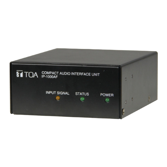
Chapter 2: Products Description 2.2 Interface Description Front Back ①INPUT SIGNAL: input indicator light ②STATUS: status indicator light ③POWER: power indicator light ④Grounding switch ⑤INPUT VOLUME: input volume adjusting knob, the input volume adjusting, clockwise direction is increase the volume, counterclockwise is decrease the volume. ⑥RESET: pressing the button to restore the factory default IP (or upgrade firmware )、broadcasting IP. - Page 7 Chapter 3 Wiring...
-
Page 8: Chapter 3: Wiring
Chapter 3: wiring 3.1 Wiring Diagram 3.1 Wiring diagram... -
Page 9: Installation Description
Chapter 3: Wiring 3.2 Installation description 3.2 Installation description 3.2.1Wall-mounted installation diagram It is s only for single device installation. 3.2.1.1 Reference size (unit: mm) 3.2.1.2 Please refer to the following picture for installation: Using the countersunk head screw M3*6 to fasten the two wall-mounted bracket in the two sides of the device, and then installing the device in a suitable position by screw(non standard) or expansion screw(non standard). - Page 10 Chapter 3: Wiring 3.2 Installation description 3.2.2 Device cabinet installation diagram (2 sets of IP-1000AF installation) It is suitable for 2 devices installation, and it need device cabinet installation bracket suite for optional configuration. 3.2.2.1 Reference size (unit: mm) 3.2.2.2 Please refer to the following picture for installation: Using the half cabinet mounting bracket(MB-IP10B-BK) to fix the two devices as the mentioned method, then using length M5*12 and above screw to install the devices in the suitable place.
- Page 11 Chapter 3 Wiring 3.2 Installation description 3.2.3 Device box installation diagram (4 sets IP-1000AF installation) It is suitable for 4 devices installation, and it needs installation bracket suite for optional configuration. 3.2.3.1Reference size (unit: mm) 3.2.3.2 Please refer to the following picture for installation: Using the half cabinet mounting bracket(MB-IP10B-BK) to fix the four devices as the mentioned method, then using length M5*12 and above screw to install the devices in the suitable place.
-
Page 12: Reference Size
Chapter 3: Wiring 3.3 Reference size 3.3 Reference size (unit: mm) Note: the attached floor mat (10*3) can be pasted on the bottom of the device it is for increasi ng the device antiskid effect on the desk. - Page 13 Chapter 4 System setting by browser...
-
Page 14: Chapter 4: System Setting By Browser
Chapter 4: System setting by browser 4.1 Entering into browser 4.1 Entering into browser Step 1: Please input IP address of the IP audio interface unit (factory defaults is 192.168.1.101), then press Enter. Step 2: Please input the user name and password in the login window of the Web page (the defaults is admin). -
Page 15: Network Parameters
Chapter 4: System setting by browser 4.2 Network parameters 4.2 Network parameters Identify the unique number of the speaker and it can’t be repeated with Device number other terminals or hosts. IP address IP address of IP audio interface unit The defaults port number is 2046, please don’t modify it if not in specially Device port situation. -
Page 16: Audio Parameters
Chapter 4: System setting by browser 4.3 Audio parameters 4.3 Audio parameters Broadcast coding, PCM means no data be compressed, ADPCM means Coding mode packed data (low network data value). Line input volume The volume of audio line input(0~15). Broadcasting IP audio interface unit sampling rate in broadcasting. - Page 17 Chapter 4: System setting by browser 4.4 Firm alarm parameters 4.4 Fire alarm parameters When control input in the status which isn’t trigger the control input interface,, the status decide the alarm way.(open circuit alarm or closed Status circuit alarm) NO: control input interface is closed to trigger the alarm.
-
Page 18: Web Management
Chapter 4: System setting by browser 4.5 WEB management 4.5 WEB management You can modify the account number and password of the login Web page in the Web management parameters. - Page 19 Chapter 4: System setting by browser 4.6 Restarting device 4.6 Restarting device User can click “restart device” to restart the device.
-
Page 20: Resetting To Defaults
Chapter 4: System setting by browser 4.7 Resetting to defaults 4.7 Resetting to defaults Resetting defaults: all the parameters will reset to defaults. -
Page 21: Firmware Upgrade
Chapter 4: System setting by browser 4.8 Firmware upgrade 4.8 Firmware upgrade Clicking into the firmware upgrade mode to enter the firmware upgrade interface. Click browse in the upgrade firmware interface, please select the correct upgrade files, click on "upgrade", it will automatically restart after completed the upgrade. -
Page 22: System Log
Chapter 4: System setting by browser 4.9 System log 4.9 System log It can be browsed of the unit log in the Web page, click “delete all logs” can delete all the logs in the Web page. - Page 23 Chapter 5 Appendix...
-
Page 24: Chapter 5: Appendix
Chapter 5: Appendix 5.1 Specification 5.1.1 IP Audio Interface Unit IP-1000AF Model IP-1000AF Power DC24V Power consumption Less than 85mA Range: 1Vrms (Max:2Vrms), unbalanced, impedance 10KΩ Audio input Range: 1Vrms, unbalanced, impedance 600Ω Audio output Line input (sampling rates:22K):20~10kHZ Frequency response... - Page 25 TOA Corporation 201611...
Need help?
Do you have a question about the IP-1000AF and is the answer not in the manual?
Questions and answers