
Related Manuals for FlexDSL ORION 2


Summary of Contents for FlexDSL ORION 2
- Page 1 User Manual NTU Orion 2 FlexDSL ORION 2(+) NTU DEVICES TECHNICAL DESCRIPTION AND OPERATIONS MANUAL Version Document name UM_Flexdsl-NTU-Orion2_V1-4.Doc Revision 18. November 2008...
- Page 2 User Manual NTU Orion 2 © Copyright ©2008 by FlexDSL Telecommunications AG. The content of this publication may not be reproduced in any part or as a whole, transcribed, stored in a retrieval system, translated into any language, or transmitted in any form or by any means, electronic, mechanical, magnetic, optical, chemical, photocopying, manual, or otherwise, without the prior written permission of FlexDSL Telecommunications AG.
-
Page 3: Table Of Contents
SELECTION GUIDE ......................8 INTRODUCTION ........................9 TECHNICAL DESCRIPTION ....................10 Application and general information about FlexDSL Orion 2 devices ......10 Main features of FlexDSL Orion 2 devices ..............11 Description of FlexDSL Orion 2 NTU devices .............. 12 3.3.1... - Page 4 User Manual NTU Orion 2 4.6.2.2 <CONNECT N:1..13/R> command ..............54 4.6.2.3 <LINK [SN/00/FE]> > command ..............54 4.6.2.4 <LINKCLEAR> command ................55 4.6.3 Performance management menu ................. 55 4.6.3.1 <H> command ....................55 4.6.3.2 <TCPIP> command ..................56 4.6.3.3 <MAC>...
- Page 5 APPENDICES ........................106 Example 1 of configuration of Orion 2 devices ............106 7.1.1 Configuration of the FlexDSL Orion 2 device at the Central Office premises..106 7.1.2 Configuration of the FlexDSL Orion 2 device at the Customer Premises... 107 7.1.3...
-
Page 6: Version Control
User Manual NTU Orion 2 TECHNICAL SPECIFICATION ..................114 Interfaces ........................114 8.1.1 xDSL Line Interface .................... 114 8.1.2 E1 Line Interface ....................114 8.1.3 Monitor Interface ....................114 8.1.4 Ethernet ......................114 Power Supply ......................115 Environmental ......................115 8.3.1... -
Page 7: Safety Regulations
PROTECTIVE ERTH CONDUCTOR. INCORRECT USE OF THIS DEVICE, USE IN ANY OTHER ENVIRONMENT AND/OR HOUSING THAN PROVIDED BY FLEXDSL MIGHT LEAD TO HARMFUL CONDITIONS. FAILURE TO FOLLOW THESE PRECAUTIONS MAY RESULT IN DEATH, SEVERE INJURY OR PROPERTY DAMAGE. Please read this manual carefully before operating the system. -
Page 8: Selection Guide
User Manual NTU Orion 2 1 SELECTION GUIDE... -
Page 9: Introduction
NTU Orion 2 2 INTRODUCTION The present document describes devices of the FlexDSL Orion 2 NTU family. The document contains the technical description of the devices, installation, configuration, and operation instructions. Appendices containing additional information about the system are also an integral part of the present document. -
Page 10: Technical Description
The devices can be powered from local DC sources. Regenerators and NTUs can be fed both locally or remotely from LTUs. Figure 1.1 presents an example of organization of data transmission systems with the help of modems of the FlexDSL Orion 2 family. Other variants of the usage of this equipment are also possible. -
Page 11: Main Features Of Flexdsl Orion 2 Devices
- relative air humidity – from 5% … 85% at +25°C. Main features of FlexDSL Orion 2 devices FlexDSL Orion 2 modems represent the next generation of modems of the FlexDSL Orion family and have the following features: 1. A new type of line encoding – TC-PAM32 (TC-PAM16 is also supported). -
Page 12: Description Of Flexdsl Orion 2 Ntu Devices
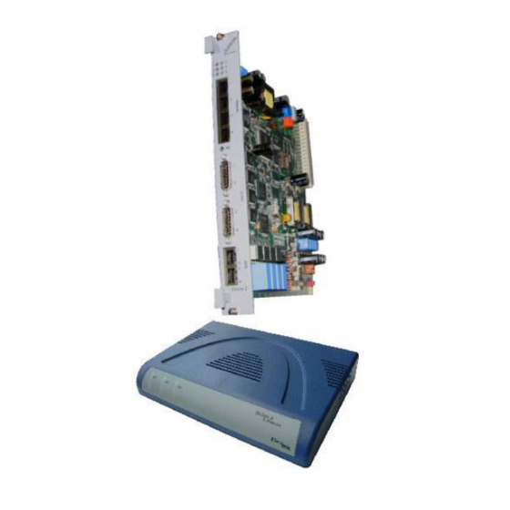
User Manual NTU Orion 2 Description of FlexDSL Orion 2 NTU devices From the mechanic point of view, the device represents a case made of shockproof polystyrene to withstand harsh environmental conditions, the case containing the basic elements of the device. - Page 13 User Manual NTU Orion 2 Figure 3.2: Top- and front view Orion 2 NTU devices...
- Page 14 User Manual NTU Orion 2 Figure 3.3. Rear view FlexDSL Orion 2 NTU devices FG-PAM-SA2N-2E1B/Eth,V51 FG-PAM-SAN-E1B/Eth,V50 FG-PAM-SA2N-Eth,V53; FG-PAM-SA4N-Eth,V54 FG-PAM-SAN-Eth,V52 (from top to bottom).
-
Page 15: Remote Power Supply, Wetting Current- Supply And Consumption Modes
User Manual NTU Orion 2 Figure 3.4. Top view FG-PAM-RAIL2N-2E1B/Eth, V51devices Figure 3.5. Front view FG-PAM-RAIL2N-2E1B/Eth, V51 devices 3.3.1 Remote power supply, wetting current- supply and consumption modes The wetting current supply and remote power supply modes can be changed by using jumpers and the management PC. -
Page 16: Compatibility Of Wetting Current Supply And Remote Power Supply Modes
User Manual NTU Orion 2 • When working with lines and the a junction box, the xDSL cable should be disconnected from the device supplying the remote power; • The insulation of cable pairs, junctions (junction boxes, plinths, etc.) should correspond to norms and standards of the network;... -
Page 17: Description Of Flexdsl Orion 2 Interfaces
The operation modes described below refer to the line interface of the device. The FlexDSL Orion2 devices can have 1, 2 or 4 xDSL interfaces. The interfaces can operate independently of each other as well as can be combined to operate in the multipair mode. -
Page 18: Master/Slave/Auto
Master/Slave operation modes. 3.3.2.1.2 Multipair modes FlexDSL Orion2 modems and regenerators support the multipair mode. If 2, 3 or 4 DSL channels are configured to operate in the multipair mode, they function at the same clock frequency and line rate as one DSL channel with doubled, tripled or quadrupled transmission capacity. - Page 19 E1 stream and Ethernet packets are transmitted. The use of this scheme involving the FlexDSL Orion2 equipment allows one to increase the transmission range, compared to the use of only one xDSl channel (the adavantage in the transmission range will depend on the cable parameters and noise immunity).
-
Page 20: Reservation
The <MULTIPAIR> command is used to configure this operation mode. 3.3.2.1.3 Reservation Reservation is provisioned for 2- and 4-channel FlexDSL Orion2 devices. The main task of reservation is to transmit the most important data even in the case of a failure of one or several DSL connections (contingency). - Page 21 User Manual NTU Orion 2 Table 3.5 Examples of reservation with two channels. Normal mode DSL2 down DSL1 down Mode DSL1 DSL2 DSL1 DSL2 DSL1 DSL2 E1-1, E1-2, E1-1, DSL1: baserate 72, 40 TS 29 TS 40 TS E1-1, DSL2: baserate 61...
- Page 22 User Manual NTU Orion 2 Normal Mode Central Office Customer Premises Equipment E1-1, 57 TS WAN (ETH1) Transmitted via DSL1 ETH1 Ethernet Ethernet ETH1 Network Network DSL1 FlexDSL FlexDSL Orion2 Orion2 DSL2 G.703 (E1-1) G.703 (E1-1) G.703 (E1-2) G.703 (E1-2) G.703 (E1-3)
- Page 23 User Manual NTU Orion 2 At the same time, while for a two-channel system the replacement of channels is trivial in the case of contingency, in tre- and four-channle systems different variants are possible. However, any system with the reservation mode follows a strict logic of channel substitution because by default the system operates under conditions of incomplete data transmission, i.e., unreliable...
-
Page 24: Automatic Configuration Of A Link
User Manual NTU Orion 2 3.3.2.1.4 Automatic configuration of a link FlexDSL Orion2 devices allow one to configure the link in accordance with the Master-modem configuration. This mode is available for the following links: • Point-point single-channel links; • Point-point multichannel links with independent channels;... -
Page 25: E1 Interface (2 Mbit/S G.703/G.704)
Figure. 3.10 Example No. 3 of automatic configuration of a link FlexDSL Orion2 regenerators are configured similarly to the above examples. 3.3.2.2 E1 interface (2 Mbit/s G.703/G.704) The operation modes are described below refer to the E1 interfaces. -
Page 26: Transparent And Itu-T G.704
User Manual NTU Orion 2 3.3.2.2.1 Transparent and ITU-T G.704 In the transparent mode, the E1 data will be transmitted over the DSL without any changes. The transparent mode is only possible for transmission rates of no less than 2056 Kbit/s when transmitting one E1 stream in this mode and of no less than 4104 Kbit/s when transmitting both E1 streams in this mode. -
Page 27: Ais Detection
The following sources can serve as reference timing signals for a device with the E1 network interface in the xDSL direction: 1. An external generator (for SubRack FlexDSL Orion 2 devices) (EXTERNAL). 2. A signal from the first input E1 stream (E11) (in its presence). -
Page 28: Ethernet Interface
The FlexDSL Orion 2 equipment supports two priority queues when sending packets – a high priority queue and a low priority queue. - Page 29 A 4-port Ethernet switch is embedded in the printed board of LTUs. In the software of FlexDSL Orion 2 devices of the V9 type, the group of physical ports ETH1, ETH2, ETH3 and ETH4 is combined logically into one LAN port (VLAN tag, TRUNK/ACCESS, QoS, priority queues of Ethernet packets), the configuration being performed simultaneously for physical Ethernet ports.
- Page 30 User Manual NTU Orion 2 Internal Management Port Port 2 Virtual port (Telnet management) VLAN Port 1 Port 2 DSL1 WAN1 WAN2 Switch (phisical socket) Port 4 Ethernet Network Figure 3.13 Internal Switch for single-channel devices (for example, FG-PAM-SAN-E1B/Eth, V50).
-
Page 31: An Integrated Switch Of 64-Kbit/S Time Slots
Ethernet packets of the VLAN format are always transmitted over the xDSL or E1 interfaces in FlexDSL Orion 2 devices. In this case, the data of Assess ports are first transformed into Ethernet packets of the VLAN format according to the specified rules and then are transmitted over the line interface. -
Page 32: Mode Of Simultaneous Transmission Of Time Slots Of E1 And Ethernet Data
User Manual NTU Orion 2 Table 3.6 Examples of the correspondence between the data transmission rates for a modem and transmitted time slots of the E1 stream for this transmission mode in a single-channel device. Time slots of E1 streams (first... - Page 33 User Manual NTU Orion 2 Figure 3.15 Example of distribution of time slots in an xDSL frame at a line rate of 89x64 kbit/s in the mode when both E1 interfaces and both internal WAN1 and WAN2 ports are used for the...
-
Page 34: Test Loops
User Manual NTU Orion 2 3.3.4 Test loops To simplify the device start-and-adjustment, the system provides activation of test loops on E1 interfaces or the line interface of the device. Master Regenerator Slave Interface Interface LOOP1 LOOP2 1:1 LOOP2 1:1... -
Page 35: Performance Monitoring
User Manual NTU Orion 2 3.3.4.2 Performance monitoring The transmission performance of a link can be monitored in two different ways. The signal quality is typically used during installation and maintenance procedures, whereas the G.826 error performance parameters are used for long term evaluation of operating links and during acceptance testing. -
Page 36: Bert Test
User Manual NTU Orion 2 The G826 and G826 E1 command (the Performance management menu) are used to view the G.826 error performance statistics. 3.3.5 BERT test BERT testing is provided in a simple way. It’s preferred to switch on the Loop2 on the remote unit (slave) and setup the BERT on the master unit. - Page 37 User Manual NTU Orion 2 Table 3.7 “The device statuses according to the statuses of LEDs”. G.703 1, DSL 1 G.703 2, Device Status DSL* DSL 2 G703* Power failure or power is off Hardware or software failure Red blinking...
-
Page 38: Alarm Leds
3.4.2 Alarm LEDs If an alarm appears on any of Orion 2 devices (Master or Slave), the alarm LEDs are lit with red or amber. The Table below presents alarm conditions with the help of alarm LEDs.: Table 3.9 “Alarm LEDs of an Orion 2 device”. -
Page 39: Management Of Flexdsl Orion 2 Devices
Management of FlexDSL Orion 2 devices with Ethernet interfaces 3.5.2.1 Telnet The front panel of FlexDSL Orion 2 devices contains the Ethernet connector. The local network containing the management computer (or the PC itself) can be connected to this connector. -
Page 40: Web
Ethernet interface. Any WEB browser is used to access the WEB interface of the FlexDSL Orion 2 device (the WEB browser is installed on a user PC and is used to search and display information in the network). To display the WEB browser, you should enter http://X.X.X.X/. - Page 41 User Manual NTU Orion 2 Figure 3.20 “Table of G.826 error performance parameters according to ITU-T G.826” Figure 3.21 “Table of xDSL performance parameters FlexDSL Orion 2 devices”.
- Page 42 User Manual NTU Orion 2 Figure 3.22. “Table of E1 statistics (according to ITU-T G.826) for FlexDSL Orion 2 devices” Figure 3.23 “Table of TCP/IP, ICMP statistics”.
- Page 43 User Manual NTU Orion 2 Figure 3.24 “Table of LAN (Ethernet), WAN1 and WAN2 statistics”. More detailed information about statistics and alarm statuses of the device is presented in Section 4.6.2 of the present document. All the tables displayed are dynamic. The parameters in the tables are refreshed every 5 seconds.
-
Page 44: Snmp
NTU Orion 2 3.5.2.3 SNMP The SNMP protocol is used to monitor statuses, to configure and manage FlexDSL Orion 2 devices. In this case, the control computer should have a special SNMP program installed. FlexDSL Orion 2 devices support SNMP v1. - Page 45 User Manual NTU Orion 2 • to configure the device, to control configurations (use, acknowledge), backup configurations and restore configurations. • to view and clear G.826 statistics for E1 and DSL. • to view alarm statuses. Every variable of the Nateks-MIB, as well as of other MIB files has a detailed description in the MIB file itself.
- Page 46 User Manual NTU Orion 2 Figure 3.27 SNMP – “Alarm statistics”. Figure 3.28 SNMP – “Loading of the NATEKS-MIB via the WEB interface”.
-
Page 47: Programming Guide
User Manual NTU Orion 2 4 PROGRAMMING GUIDE Command structure The command structure is conform to the ITU-T M.3400 Rec. for the telecommunication management networks: Table 4.1 Command structure. Sub-set Short-form Performance management Fault and maintenance management Configuration management... - Page 48 User Manual NTU Orion 2 Figure 4.1 Command set tree for NTU, NxDSL, NxE1, 1xEth devices.
- Page 49 User Manual NTU Orion 2 Figure 4.2 Command set tree for NTU, NxDSL, 1xEth devices.
-
Page 50: Orion 2 Software
NTU Orion 2 Orion 2 software Every Orion 2 device can contain up to two version of the software in EEPROM: unchangeable (standby) software (software No. 1) and upgradeable software (software No. 2). Two versions are necessary to prevent the device failure due to downloading of faulty or damaged software or due to hardware failure (for example, power cutoff, etc.) during downloading of the new... - Page 51 User Manual NTU Orion 2 • configuration parameters applied after the restart; • configuration parameters applied instantly; • configuration parameters requiring confirmation. Configuration changes, which are used after the restart, are written into the startup configuration, but before the restart the device continues functioning according to its “old”...
-
Page 52: Groups Of Commands Requiring Confirmation
Figure 4.5 Operations with configuration parameters that should be confirmed. Groups of commands requiring confirmation The following four groups of parameters require confirmation in Orion 2 devices: LINE, NET, VLAN and SNMP. Configurations of each group change by using special commands (see Fig. -
Page 53: Command Syntax
User Manual NTU Orion 2 Command syntax The following rules are used to describe commands: • parameters in angular brackets < > are obligatory; • parameters in direct brackets[ ] are not obligatory; • the symbol ( / ) between parameters requires to enter one of the listed parameters;... -
Page 54: System Invitation
User Manual NTU Orion 2 4.6.1.1 System invitation The following format of the system invitation is used in all menus: <cc>_<addr>_<sf>>, сс is the device mode [RR – regenerator, CO – Master; CP – Slave; CX – a modem with both types of interfaces, CA –... -
Page 55: Linkclear> Command
User Manual NTU Orion 2 Example: • LINK 10 - Establish connection to subrack unit with slot number 10. Available only for subrack units. • LINK 00 - Establish monitor control node. Available only for subrack units. • LINK FE - Establish monitor control node. Available only for common CLI RS232 Terminal units. -
Page 56: Tcpip> Command
User Manual NTU Orion 2 4.6.3.2 <TCPIP> command command displays a summary table of statistics of ICMP, IP and TCP protocols, <TCPIP> i.e., packets processed by the internal INT interface. CP_PM>TCPIP -- TCP/IP Statistics ------- ICMP ------- IP -- IP Frag ------ TCP ------------... -
Page 57: Mac> Command
User Manual NTU Orion 2 4.6.3.3 <MAC> command The <MAC> command displays the table of the Ethernet interface statistics of the modem. CO_PM>MAC -- MAC Tx status ------------------- MAC Rx status --------------------- Tx packets: Rx packets: 13356 Tx good: Rx good:... -
Page 58: G826> Command
User Manual NTU Orion 2 4.6.3.4 <G826> command The <G826> command displays the ITU-T G.826 performance parameters of the line. Depending on the number of DSL channels in the system, a table is displayed containing 1, 2 or 4 columns of data. -
Page 59: G826 Е1> Command
User Manual NTU Orion 2 4.6.3.5 <G826 Е1> command The <G826 Е1> command displays the ITU-T G.826 error performance parameters on the E1 side. If the CRC4 mode is on for both channels, the following parameters are displayed: CO_PM>G826 E1 ~~~~~~~~~~~~~~~~~~~~~~~~~~~~~~~~~~~~~~~~~~~~~~~~~ G.826 Error Performance... -
Page 60: Allg826> Command
User Manual NTU Orion 2 Definitions: CRC4: – Cyclic redundancy check indicating errored submultiframes received on the E1 side; E-bit: – CRC4-indication bit denoting received errored submultiframes received on the E1 side; FAS: – Errored frame alignment signal received on the E1 side;... -
Page 61: Linkstat> Command
User Manual NTU Orion 2 4.6.3.9 <LINKSTAT> command The <LINKSTAT> command will show an steady quick status of the whole link. -------------------------------------------------------------------------------- DSL 1 -------------------------------------------------------------------------------- CO link up RR1 (N) link up RR1 (C) link up CP link up -------------------------------------------------------------------------------- CO_PM>... -
Page 62: Netstat> Command
User Manual NTU Orion 2 4.6.3.12 <NETSTAT> command The <NETSTAT> command displays statistics of LAN (Ethernet), WAN1 – WAN4 and INT (internal management port) interfaces. CO_PM>NETSTAT -------------------------------------------------------------------------------- Statistics WAN1 WAN2 -------------------------------------------------------------------------------- Bytes sent Packets sent HP packets sent LP packets sent... -
Page 63: Fault And Maintenance Management Menu
User Manual NTU Orion 2 4.6.4 Fault and maintenance management menu After typing “2” in the main menu and pressing enter, the following message is displayed: Fault and maintenance management activated Enter <M> to return to MAIN, or <H> for HELP information 4.6.4.1 <H>... -
Page 64: Nm> Command
User Manual NTU Orion 2 4.6.4.2 <NM> command command displays the ITU-T G.991.2 Noise Margin performance parameters. <NM> (The maximum possible increase in the noise margin at which the BER is expected to be less that 10 The action of the <NM> command terminates by entering any other command or by pressing “enter”. -
Page 65: Status Eth> Command
User Manual NTU Orion 2 Power backoff Output signal power reduction[dB] Far end power Far end signal power reduction [dB] (in the current version invalid backoff values are displayed) Loop attn Attenuation in the loop [dB] Maximum possible increase in the noise margin for which the BER... -
Page 66: Mactable> Command
User Manual NTU Orion 2 4.6.4.5 <MACTABLE> command The <MACTABLE> displays the dynamic table of MAC addresses: CO_FMM>MACTABLE 00:0c:6e:ea:ee:4a 00:c0:26:a3:6e:a2 00:c0:26:31:66:3e 00:0c:f1:6e:19:8c 00:0f:24:b5:65:d0 00:1f:00:00:01:eb 02:01:00:00:00:00 00:c0:df:0e:b5:40 00:80:48:15:72:0b 00:05:5d:c7:e6:8f 00:c0:26:a3:65:32 00:c0:26:a7:cd:13 00:c0:26:31:5d:61 00:80:48:15:d3:06 00:c0:26:31:65:07 00:08:0d:b1:e9:fa CO_FMM> Option: С – update the table continuously. -
Page 67: Loop1 On/Off [N=1
User Manual NTU Orion 2 Table 4.3 «<ALARM> - definitions». Definitions (E1-1, E1-2): LOS-S Loss of signal on the Е1 side LFA-S Loss of frame alignment on the E1 side AIS-S Receiving AIS on the E1 side AIS-R Receiving AIS on the E1 side by a remote device BER-S The block error rate on the Е1 side exceeded the admissible value... -
Page 68: Loop2 N:addr On/Off> Command
User Manual NTU Orion 2 4.6.4.8 <LOOP2 N:ADDR ON/OFF> command The <LOOP2 N:ADDR ON/OFF> command activates/deactivates the remote loopback on the line interface. The parameter N:ADDR sets the number N of the DSL interface and the device address (as in the CONNECT command). -
Page 69: Reset> Command
User Manual NTU Orion 2 4.6.4.11 <RESET> command The <RESET> command restarts the device. CP_FMM>RESET 4.6.4.12 <AСO [GROUP ON/OFF])> command The <AСO> command without additional parameters lists deactivated alarm relays. CO_FMM>ACO E1-1, ETHERNET CO_FMM> The <ACO [GROUP ON/OFF]> command activated/deactivates the GROUP alarm relays. -
Page 70: Softupdate> Command
User Manual NTU Orion 2 For example: if it is necessary to deactivate alarm statuses of the group Е1-1 and DSL, enter the ACO command twice: first, with the parameter Е1-1, and second, with the parameter DSL. CP_FMM>ACO E1-1 ON E1-1, ETHERNET CP_FMM>ACO DSL ON... -
Page 71: Apply /All/Net/Line> Command
User Manual NTU Orion 2 ver – the number of the software version. date – the date of the software creation. length – the size in bytes. CRC OK/FAIL – a label showing if the software is damaged or not. -
Page 72: Restore> Command
User Manual NTU Orion 2 4.6.4.19 <RESTORE> command The <RESTORE> command restores the startup configuration from the backup configuration, which is written in the EEPROM. As a result, values from the backup configuration are written into the startup configuration. For example: CO_FMM>RESTORE... -
Page 73: Load> Command
User Manual NTU Orion 2 SNMP.TRAPIP.0 00 00 00 00 SNMP.TRAPIP.1 00 00 00 00 SNMP.COMMUNITY 43 4F 4D 4D 4F 4E 00 20 60 00 00 13 00 02 B2 3C\ 00 18 65 44 00 05 5E 2C FF FF FF FF 00 17 59 F8\ M.ALARM_CUTOFF... -
Page 74: Powermode [0
User Manual NTU Orion 2 4.6.4.23 < POWERMODE [0..5]> command The < POWERMODE [0..5]> command initialized the desired power mode. Normal unit power consumption mode. No power saving features enabled Normal unit power consumption mode. Power consumption increases very slowly during startup (soft start). -
Page 75: Tlm S [N:[Rnn-Rkk]] [Abc]> Command
User Manual NTU Orion 2 4.6.4.25 <TLM S [N:[Rnn-Rkk]] [ABC]> command This command sets NTU reaction on external alarms of regenerators. Parameters: selected line Rnn - Rkk: regenerator or the range of regenerators to set reaction for. Example: 'R1', 'R9', 'R04', 'R1-R4', 'R07-R09'. -
Page 76: Bert> Command
User Manual NTU Orion 2 4.6.4.26 <BERT> command The <BERT> command allows one to enter the submenu for BER Testing subsystem. Type <M> to return to the main menu. 4.6.4.27 <H> command Type and the monitor lists all available commands in the fault and maintenance sub-menu: <H>... -
Page 77: Show > Command
User Manual NTU Orion 2 4.6.4.31 <SHOW > command This command shows the actual status of the BERT. CO_BERT>SHOW Testing E1-1, External output -------------------------------------------------------------------------------- BERT status G.826 -------------------------------------------------------------------------------- Sync : Sync loss Errors Alarms : ALL 0s Errored seconds Bitrate TX... -
Page 78: Configuration Management Menu
User Manual NTU Orion 2 4.6.5 Configuration Management menu After typing “3” in the main menu and pressing enter, the following message will be displayed: Configuration management activated Enter <M> to return to MAIN, or <H> for HELP information The content of the configuration management menu mainly depends on the operation mode of the device. -
Page 79: Auto [On/Off]> Command
User Manual NTU Orion 2 APPLY [ALL/GROUP] Apply changes to running configuration GSCOMPAT [ON/OFF] Set GS compatibility mode on and off NMTHR [N/OFF]] Set the Noise Margin alarm threshold LATHR [N/OFF] Set the Line Attenuation alarm threshold MODE [N] Sets the number of DSL channels to N... - Page 80 User Manual NTU Orion 2 TS into DSL 0-31 0-31 TS into WAN NONE NONE -------------------------------------------------------------------------------- CO_CM> For devices in the CA mode: CA_CM>CONFIG -------------------------------------------------------------------------- Running Line Configuration -------------------------------------------------------------------------------- xDSL DSL1 DSL2 Mode ---- All slave, AUTO ON ---- Extended rates:...
- Page 81 User Manual NTU Orion 2 Group of E1 parameters G.704 framing Framing mode CRC4 CRC4 mode AIS Detection AIS detection mode AIS Generation AIS generation mode E1 clock Clock source TS into DSL List of time slots of E1 transmitted/received overt DSL TS for WAN List of time slots of E1 used for WAN data список...
-
Page 82: Master On/Off N> Command
User Manual NTU Orion 2 4.6.5.4 <MASTER ON/OFF N> command The <MASTER ON/OFF N> activates/deactivates the «MASTER» mode on the interface with the number N. The <MASTER ON> activates the MASTER mode. The <MASTER OFF> command activates the SLAVE mode. -
Page 83: Baserate K/Auto [N=1
User Manual NTU Orion 2 4.6.5.6 <BASERATE K/AUTO [N=1..4]> command K [N=1..4]> The <BASERATE command sets the transmission rate K over the line xDSL interface, where N is the number of the interface. For PAM16 the available rates (BASERATE) lie in the range from 3 to 60, and for PAM32 – from 12 to 89. -
Page 84: Annex A/B/Ab [N=1
User Manual NTU Orion 2 of the xDSL stream (57*64 = 3648 kbit/sec) will be used to transmit WAN (Ethernet) by the <PAYLOAD E1-1, WAN> command. For modems with one xDSL channel, the command is as follows: CO_CM>PAYLOAD WAN CO_CM>PAYLOAD E11,WAN CO_CM>PAYLOAD NONE... -
Page 85: Reserve [List]>,
User Manual NTU Orion 2 The two-pair mode can be activated simultaneously for two pairs of channels: 1-2 and 3-4. The 2+2 mode is also possible: CO_01_CM>MULTIPAIR 2+2 4.6.5.12 <RESERVE [list]>, <RESERVE [list] [list]> command The <RESERVE> command allows one to combine xDSL channels into groups in order to reserve them.Command -
Page 86: Dslts List/None [N=1
User Manual NTU Orion 2 CO_CM>AISGEN ON CO_CM>AISDET ON 4.6.5.16 <DSLTS list/NONE [N=1..4]> command command sets transmitted/received time slots of the given <DSLTS list/NONE [N=1..4]> E1 channel to be transmitted over the xDSL channel. Here, N is the number of the E1 interface. -
Page 87: Id N> Command
User Manual NTU Orion 2 Note: It is also possible to set an empty password (in this case, the password is not requested while opening the telnet session). This command sets the password only to access the device over the telnet protocol. When managing the devices via the RS-232 interface, the password is not requested. -
Page 88: License [License_Key]> Command
User Manual NTU Orion 2 4.6.5.27 <LICENSE [LICENSE_KEY]> command With the <LICENSE [LICENSE_KEY]> command its possible to display or to enter the license key. 4.6.5.28 <MODE N> command The <MODE N> command sets number of xDSL interfaces system will operate with. -
Page 89: Netconfig [R/N/S/B]> Command
User Manual NTU Orion 2 4.6.5.31 <NETCONFIG [R/N/S/B]> command Without parameters the command displays the running configuration of the <NETCONFIG> network subsystem and interfaces: CO_09_NET>NETCONFIG -------------------------------------------------------------------------------- Running Network Configuration -------------------------------------------------------------------------------- VLANs & QoS Interfaces WAN1 WAN2 Mode access trunk trunk... - Page 90 User Manual NTU Orion 2 QoS for HPQ Minimum priority of a packet to be transmitted via the high priority queue. Slicing for LPQ Size of slicing for low priority packets Ethernet port configurations Speed/Duplex Operation mode of the Ethernet interface...
- Page 91 User Manual NTU Orion 2 The NETCONFIG command always displays the running configuration. If the new configuration differs from the running one, the NETCONFIG command displays the running configuration and a warning: CO_09_NET>NETCONFIG -------------------------------------------------------------------------------- Running Network Configuration -------------------------------------------------------------------------------- VLANs & QoS...
-
Page 92: Interface Name Command Param > Command
User Manual NTU Orion 2 When a command used to change the configuration of the VLAN or network, for example, INTERFACE, VID, SETIP, NETMASK, is successful, the new configuration is applied similarly to command. This is determined by the fact that configurations of the group <NETCONFIG N>... -
Page 93: Ethsd 10/100/Auto H/F [N=1
User Manual NTU Orion 2 The VID command is used to assign the VLAN name to its number. The List of VLANs, received by the interface is checked only in the TRUNK mode. In the ACCESS mode, only one VLAN (its default VLAN) is received by the interface although there can be added special MAC addresses for which another VLAN is assigned. -
Page 94: Gateway X.x.x.x> Command
User Manual NTU Orion 2 4.6.5.36 <GATEWAY X.X.X.X> command The <GATEWAY X.X.X.X> sets the default IP address of the router. 4.6.5.37 <NETMASK X.X.X.X> command The <NETMASK A.B.C.D> command sets the subnet mask of the modem. 4.6.5.38 <VID [1-8] ID> command command sets VID for the VLAN with the number 1…8 equal to the ID... -
Page 95: Snmpset On/Off> Command
User Manual NTU Orion 2 4.6.5.42 <SNMPSET ON/OFF> command The <SNMPSET ON> command enables processing SNMP SET requests, which allows one to configure and manage the device, however, this command makes the device sensitive to attacks over SNMP in unprotected PC networks. -
Page 96: Software Downloading
User Manual NTU Orion 2 5 SOFTWARE DOWNLOADING The device hardware allows using new functions by updating the software. The downloading of the software can be performed as follows: • via the RS232 port by using the “Flash Loader” program;... - Page 97 User Manual NTU Orion 2 5. Select «Select Device» in the «Setting» menu, then select «FG-PAM» and click «Ok». 6. Select the «SSS» file and click Open. 7. Select «Connect COM» in the «Action» menu.
- Page 98 User Manual NTU Orion 2 8. Switch on the device being activated. 9. Click «Yes» in the “Flashloader” window. 10. The loading progress will be displayed in the window “Flash Loader: Send Panel”. 11. If the loading is successful, the following window will be displayed:...
-
Page 99: Software Loading Via The Com Port (The 1K-Xmodem Protocol)
User Manual NTU Orion 2 12. Click «Ok». 13. Select «Disconnect COM» in the «Action» menu. 14. Switch off the device being loaded and disconnect it from the PC. 15. Follow items 1, 2, 7 – 15 to load the software into other devices. - Page 100 User Manual NTU Orion 2 5. Then, the Connect To window is displayed. Select the COM port connected to the shelf in the “Connect Using” drop-down menu. Click OK. 6. Configure the parameters of the COM port (COM properties). •...
- Page 101 User Manual NTU Orion 2 7. Select Properties in the “File” menu of the HyperTerminal program. Select the Setting tab. Select the VT100 emulation in the Emulation drop-down menu. Click...
- Page 102 User Manual NTU Orion 2 9. Select Call in the “Call” menu. (If the menu is not available, the connection is established automatically. Go to item 10.) Input %XX, where XX is the slot number in the shelf. The main menu of the device is displayed.
-
Page 103: Software Loading Via Ethernet (1K-Xmodem And Telnet)
User Manual NTU Orion 2 completed, the device stores the downloaded file into the memory. After the Send button is clicked, the “1K-Xmodem file send for…” window pops up. The window displays the software downloading statistics (the name of the file, the number of transmitted packets, the error checking method, the last error, the downloading progress, time, etc.). -
Page 104: Service Instructions
User Manual NTU Orion 2 6 SERVICE INSTRUCTIONS General requirements • Before unpacking, check if the packing box is intact and if the equipment model is consistent with that specified in the purchase contract. • Before starting operating the device, read carefully the present technical description and service instructions. -
Page 105: Evaluation Of The Quality Of The Digital Channel And Operation Parameters
(LOOP1) and G.826 statistics of E1 interfaces. If LOOP1 is activated on this network interface and the G826 statistics displays errors, a conclusion can be made that the E1 network interface of the FlexDSL Orion 2 system is configured improperly or malfunctions. -
Page 106: Appendices
User Manual NTU Orion 2 7 APPENDICES Example 1 of configuration of Orion 2 devices An example of organization of a data transmission system with the help of Orion 2 devices is presented below: Central Office Ethernet Network Repeater Point... -
Page 107: Configuration Of The Flexdsl Orion 2 Device At The Customer Premises
Confirmation of all configurations (Fault And Maintenance Management menu): <CONFIRM> – confirm all configurations (written in the startup configuration) 7.1.3 Configuration of the FlexDSL Orion 2 regenerator at the Regenerator Point. System configuration (Configuration Management menu): <DEFAULT EVERYTHING> – enable default settings Line interface configuration (Configuration Management menu): <MASTER AUTO>... -
Page 108: Example 2 Of Configuration Of Orion 2 Devices
(Enter the PING command to check IP addresses in all networks connected to the FlexDSL Orion2 equipment). 7.2.1 Configuration of the FlexDSL Orion 2 device at the Central Office premises. System configuration (Configuration Management menu): <DEFAULT EVERYTHING>... -
Page 109: Configuration Of The Flexdsl Orion 2 Device At The Customer Premises
– confirm configurations (written startup <CONFIRM> configuration) 7.2.2 Configuration of the FlexDSL Orion 2 device at the Customer Premises System configuration (Configuration Management menu): <DEFAULT EVERYTHING> – enable default settings Line interface configuration (Configuration Management menu): <MASTER OFF> – enable the Slave mode Configuration of the internal Ethernet switch (Network Management submenu): –... -
Page 110: Configuration Of The Flexdsl Orion 2 Regenerator At The Regenerator Point
User Manual NTU Orion 2 7.2.3 Configuration of the FlexDSL Orion 2 regenerator at the Regenerator Point. System configuration (Configuration Management menu): <DEFAULT EVERYTHING> – enable default settings Line interface configuration (Configuration Management menu): <MASTER AUTO> – enable automatic detection of the Master/Slave mode <BASERATE AUTO>... -
Page 111: Connectors' Description
User Manual NTU Orion 2 Connectors’ description 7.3.1 “Ethernet” connector Type – 4*RJ-45 (female), four connectors of 8 pins each. Table 7.1 “Ethernet” connector Front View Pin No. Description (PC connector) Tx+ (transmit data) Tx- (transmit data) Rx+ (receive data) -
Page 112: G703" Connector (Е1 Interface For Stand Alone And Minirack Devices)
User Manual NTU Orion 2 7.3.3 “G703” connector (Е1 interface for Stand Alone and MiniRack devices) Type – RJ-45 (female), 8 pins. Table 7.3 “G703” connector. Front View Signal Description (PC connector) RX_1/2A E1Input → CH1/2 Wire A RX_1/2B E1Input → CH1/2 Wire B Not used TX_1/2A E1 Output →... -
Page 113: Monitor" Connector
User Manual NTU Orion 2 7.3.4 “Monitor” connector Type: Sub-D9, female Table 7.4 “Monitor” connector. Pin No. Signal Description MAJ_ALARM Urgent-alarm output Transmit data (to the modem) Receive data (from the modem) Not Used (Do not connect) SGND Signal ground 3.3Vdc... - Page 114 User Manual NTU Orion 2 8 TECHNICAL SPECIFICATION Interfaces 8.1.1 xDSL Line Interface Specification ITU-T G.991.2-G.shdsl, ITU-T G.991.2-G.shdsl.bis Line Code TC-PAM Impedance 135Ω Transmit Power 13.5 (Annex A) or 14.5 (Annex B) dBm @ 135 Ω Number of Pairs 1,2 or 4...
- Page 115 User Manual NTU Orion 2 Power Supply Specification ETSI ETS 300 132-2 Voltage 1 x 38 ..72V over Molex type safety approved connector 38..118Vdc over xDSL Voltage for -24V models 1 x 18..72V over Molex type safety approved connector No remote power feeding allowed Power Consumption Typ.
Need help?
Do you have a question about the ORION 2 and is the answer not in the manual?
Questions and answers