Table of Contents
Advertisement
Quick Links
Advertisement
Table of Contents

Related Manuals for Hydrajaws 2008


Summary of Contents for Hydrajaws 2008
- Page 1 P a g e...
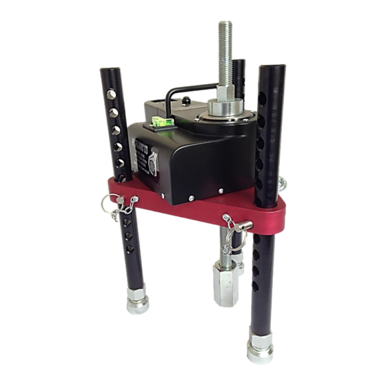
- Page 2 Figure 1 Hydrajaws® Model 2008 Pull-Out Tester It is essential that the operating instructions are read before the tester is operated for the first time. Always keep these operating instructions together with the tester. Ensure that the operating instructions are with the tester when it is given to other persons.
- Page 3 Material: stainless steel and ceramic Battery Powered (PP3) KIT CONTENTS 1. Model 2008 Tester Body 2. 22mm Operating Nut 3. 0-145kN Digital Gauge (Bluetooth version optional for recording data via suitable mobile device) 4. Offset Load Spreading Bridge plate with 10mm eye hook 5.
-
Page 4: Table Of Contents
Using optional 125kN Heavy Duty bridge DESCRIPTION The Hydrajaws model 2008 Heavy Duty Tester is designed for establishing linear loading of mechanical and resin anchors, eye type anchors, threaded bar, re-bar and structural bolts and fixings to a maximum load of 145kN. -
Page 5: Load Spreading Bridge Assembly
Figure 3 Figure 4 The bridge has been designed specifically for the model 2008 tester and directs reaction loads away from the fixing [Figure 3]. The lightweight aluminium load spreading bridge fits in the carry case disassembled [Figure 4]. The bridge is simple to assemble and adjust. -
Page 6: Setting Up For Test
SETTING UP FOR TEST Assemble the load spreading bridge. Secure the tester to the bridge if appropriate. Position the tester and bridge over the fixing and using the M20 connecting rod pass this through the tester and bridge. Connect the M20 connecting rod to fixing using the appropriate threaded adaptor [Figure 7];... -
Page 7: Operating The Tester
OPERATING THE TESTER Switch the digital gauge on (see separate gauge operating instructions on page 9). Commence applying the load to the fixing by turning the hexagon nut on the end of the operating piston in a clockwise direction by hand until tight or reading appears on gauge. -
Page 8: Changing The Gauge Battery
CHANGING THE GAUGE BATTERY The battery (PP3) is changed by removing the battery cover (2 x M3 flat head screws) in base of tester. Undo battery strap and remove battery by disconnecting. Replace battery and reassemble connections, do not over-tighten battery strap and replace cover [Figure 13]. - Page 9 Figure 18 Figure 17 Figure 19 Figure 20 P a g e...
-
Page 10: Operating Instructions Of Digital Gauge
OPERATING INSTRUCTIONS FOR DIGITAL GAUGE 1. Press button P to switch gauge on [Figure 21]. The preset program will be in ‘Normal rise and fall mode’ This will give a load reading in kN rising as the operating handle on the tester is turned clockwise. -
Page 11: Operating Instructions For Bluetooth Gauge
& eyebolts. The digital system using Bluetooth produces real time visual graphs for each test. A button and active LED on the top of the Model 2008 tester housing indicates that the tester is equipped with this feature [Figure 22]. -
Page 12: Eyebolt Testing
EYEBOLT TESTING 1. Screw the M20 connecting rod into the heavy duty clevis and ensure the thread engages fully so is flush with the block. 2. Adjust the 3 telescopic legs on the bridge so that the pin lines up with the eye under test. Place the pin through the eye and secure the clevis and pin. - Page 13 RE-BAR OPERATING INSTRUCTIONS MODEL 2008 1. The Model 2008 Portable Heavy Duty Tester will accept Rebar adaptors 6mm, 8mm, 10mm, 12mm, 14mm, 16mm, 18mm, 20mm & 22mm re- bar directly through the cylinder. Place the tester and triangular load spreading bridge directly over the re-bar by passing through the cylinder hole.
- Page 14 Figure 30 Figure 29 Figure 31 Figure 32 13 | P a g e...
-
Page 15: Using Optional 125Kn Heavy Duty Bridge
2 M8 x 15 counter sunk screws. 3. Secure the plate to the Model 2008 tester using holes marked A with the x 2 M8 x 25 counter sunk screws and this will allow the tester to be parallel when mounted on the bridge. - Page 16 Hydrajaws® Limited 1 The Courtyard Roman Way Coleshill Birmingham B46 1HQ Telephone +44 (0)1675 430370 Fax +44 (0)1675 465950 Email: tester@hydrajaws.co.uk www.hydrajaws.co.uk August 2014 15 | P a g e...
Need help?
Do you have a question about the 2008 and is the answer not in the manual?
Questions and answers