Table of Contents
Advertisement
Quick Links
Advertisement
Table of Contents

Related Manuals for Hydrajaws 2000


Summary of Contents for Hydrajaws 2000
- Page 1 2000 Model Tester Operating Instructions H Y DR A JAW S L I M I T E D...
-
Page 2: Model 2000 Parts
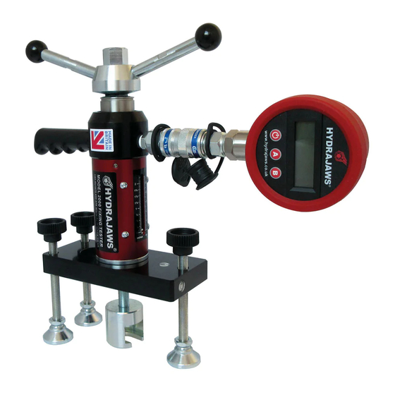
2000 Model Tester Model 2000 Parts 1. Gauge - Analogue with QR Hydraulic Coupler 2. Gauge - Digital with QR Hydraulic Coupler (optional) 3. Quick release coupling when fitted or gauge (1 & 2) 4. Tester body with 50mm/scale indicator 5. Load jaw 6. -
Page 3: Table Of Contents
The tester and 2.4 Threaded rod adaptors bridge are supplied as an integral part 2.5 The clevis adaptor of all the 2000 tester kit ranges. 3. SCAFFOLD TESTER KIT A comprehensive range of accessories 4. SAFETY HARNESS EYEBOLT... -
Page 4: Kit Contents
TESTER AND ACCESSORIES FULL KIT CONTENT RANGE: Model 2000 tester attached to 14. M12 threaded stud adaptor 150 load spreading bridge 15. M16 threaded stud adaptor Oil bottle (Detachable gauge only) 16. M20 threaded stud adaptor Analogue load gauge(s) 17. Insulation adaptor Digital load gauge(s) 18. -
Page 5: General Testing Procedure
1. GENERAL TESTING PROCEDURE SETTING UP THE TESTER Fig 1 1 Fit the appropriate adaptor to the tester. Example shown is a bolt tester adaptor. (For fitting of other adaptors please see individual instructions in this manual). 2. The tester is supplied with a locking adaptor fitted into the tester body. This locking adaptor can be removed for fitting of different adaptors by using the 3mm Ball Driver. - Page 6 1. GENERAL TESTING PROCEDURE continued.. TESTING PROCEDURE Fig 4 6. Set the red pointer on the gauge to zero - hold the tester by the grip handle and proceed to load the fastener by turning the operating handle clockwise (fig 4). CAUTION! Hold the fastener securely by the grip handle as long as the fastener is under...
- Page 7 Adjusting the handle position (fig 7) The top part of the unit can be rotated if the handle or gauge becoming obstructed by the unit legs or other objects. This is achieved by loosening the three grub screws (a) on the body using the allen key provided.
-
Page 8: Pulling Adaptors
2. PULLING ADAPTORS 2.1 THE BOLT TEST ADAPTOR Fig 9 Using the bolt test adaptor directly For M16 nuts, (fig 8) the bolt tester adaptor (a) directly engages the nut (b) in the pulling jaw. Mount the locking adaptor into the tester (see Section 1 General testing procedure). -
Page 9: Threaded Stud Adaptors
2.2 M10, M12, M16 AND M20 THREADED STUD ADAPTORS Suitable for testing sleeve and stud anchors. Fig 12 (fig 12) After the anchor has been set in accordance with the manufacturers recommendations, a suitable threaded rod (a) is screwed into the anchor and the adaptor (b) then fitted. The length of the threaded rod to be screwed into the anchor must be at least equal to the diameter of the... -
Page 10: The Clevis Adaptor
2.4 M5, M6, M8 AND M10 THREADED ROD ADAPTORS The M5 and M6 threaded rod adaptors are Fig 16 equipped with an external M12 thread for use in conjunction with the M12 threaded button adaptor. They are used primarily for testing remedial wall ties. The M8 and M10 threaded rod adaptors are equipped with an M16 external thread and the M16 nut fitted with connects to the pulling slot... -
Page 11: Scaffold Tester Kit
3. SCAFFOLD TESTER KIT The Hydrajaws Test meter is part of a KIT CONTENTS: purpose made system for testing fixings and measures the load supplied. The • 2000 model Medium Duty Tester Scaffold Tester Kit has accessories with fixed Gauge to 20kN* designed to test Scaffold Anchors and • 150mm Load Spreading Bridge Ringbolts to the requirements of the •... - Page 12 The new Proof Load testing requirement is for a tensile test of 1.5 x the design load. The Hydrajaws Scaffold Tester Kit will test all of these types to a maximum tensile load of 20kN. TG4:04 also describes six types of anchor most commonly used for anchoring scaffold ties.
- Page 13 Test rig arrangements for: Fig 21 Standard ringbolt 20kN gauge Scaffold ringbolt Drop-in anchors (concrete only)
-
Page 14: Safety Harness Eyebolt Tester Kit
For testing Safety Harness Eyebolts to the KIT CONTENTS: requirements of BS5845 and BS EN795 Protection Against Falling From A Height, • 2000 model Medium Duty Tester with Anchor Devices - Requirement for Testing fixed Gauge to 15kN* and BS 7883: 2005 BS 788: 2005 code of •... - Page 15 Fig 22 In brickwork reaction loads are directed away from the brick 15kN under test gauge In brickwork reaction loads are directed away from the brick 15kN Eyebolt gauge under test Eyebolt Clevis Clevis Cross pin Cross pin 150 load spreading bridge Swivel foot 75mm hex legs...
-
Page 16: Wall Tie Tester Kit
5. WALL TIE TESTER KIT SITE TESTING OF KIT CONTENTS: WALL TIES • 2000 model Medium Duty Tester with fixed Gauge to 5kN* The purpose of carrying out site tests on • Wall Tie Spacer Bridge wall ties is either as part of a site survey to •... - Page 17 Note: A sample of the tie may be required to confirm the right adaptor is supplied. NOW AVAILABLE: WALL TIE TESTER KIT MK 2 The Hydrajaws Wall Tie Tester Kit Mk2 is used for testing all types of remedial wall tie to meet the requirements of DD140. It is used with appropriate adaptor and mounts direct to tester.
-
Page 18: Material Bond Tester Kit
6. MATERIAL BOND TESTER KIT The bonding strengths of a wide and KIT CONTENTS: varied range of materials including • 2000 model Medium Duty Tester with concrete, screeds, repair mortars, epoxy fixed Gauge to 25kN* resin coatings, laminates, plastics, • Bond test stool with adjustable legs paints and enamels may be accurately •... - Page 19 6. Apply adhesive to substrate test surface (fig 26a). This ensures the adhesive wets out both surfaces and helps prevent interfacial failures. 7. Press the steel dolly into the substrate test surface with a firm pressure (fig 26b) DO NOT ‘seat’ the dolly by twisting it into position. If the dolly is twisted into position it will increase the likelihood of interfacial failures. 8. Remove excess adhesive from around the edge of the dolly without disturbing its position (fig 26c).
- Page 20 MATERIAL BOND TESTER KIT continued.. IMPORTANT! A low reading will be obtained if: • The pull-off tester is misaligned and not perpendicular to the specimen • The specimen is misaligned and not perpendicular to the pull-off tester • The bondline is not of uniform thickness (0.5mm) •...
-
Page 21: Optional Load Spreading Bridges
270mm or 600mm wider span bridge with telescopic legs. These are designed to attach easily to the Hydrajaws Model 2000 Tester. To install, first remove any existing load spreading bridge by removing the two Pyramid Stool positioning screws using the 3mm ball driver. -
Page 22: Care Of Tester
9. CARE OF TESTER 9.1 LUBRICATION Fig 34 Lubrication of rod This is required periodically depending on usage. Unscrew and remove operating handle. Take care to avoid moving the washer and bearing below. Grease surfaces and threads before re-assembly (fig 34). Oil refilling Connecting and disconnecting Gauges from the Tester body will eventually use... -
Page 23: Oil Refilling Instructions
9.2 OIL REFILLING INSTRUCTIONS NOTE: A tester with a fixed gauge cannot Fig 36 be filled with oil by the operator. 1. Remove the bridge and all accessories. 2. Secure the tester (e.g. in a vice or other suitable holding device if on-site) with the coupler in the vertical position. - Page 24 FOR MORE INFORMATION ON HYDRAJAWS AND A FULL RANGE OF TESTING APPLICATIONS PLEASE VISIT THE WEBSITE AT: WWW.HYDRAJAWS.CO.UK H Y DR A JAW S L I M I T E D 20/21 The Courtyard Gorsey Lane Coleshill Birmingham B46 1JA...
Need help?
Do you have a question about the 2000 and is the answer not in the manual?
Questions and answers