Table of Contents
Advertisement
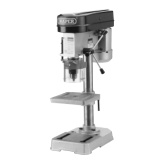
5 SPEED
BENCH DRILL PRESS
MODEL No.D13/5A
STOCK No. 33662
• INSTRUCTIONS •
IMPORTANT: PLEASE READ THESE INSTRUCTIONS CAREFULLY TO
ENSURE THE SAFE AND EFFECTIVE USE OF THIS TOOL.
09/2001
GENERAL INFORMATION
This manual has been compiled by Draper Tools and is an integrated part of the power tool equipment, which should be kept with the machine.
This manual describes the purpose for which this tool has been designed and contains all the necessary information to ensure its correct and
safe use. We recommend that this manual is read before any operation of the machine, before performing any kind of adjustment to the
machine, and prior to any maintenance tasks. By following all the general safety instructions contained in this manual, it will ensure both
machine and operator safety, together with longer life of the tool itself.
All photographs and drawings in this manual are supplied by Draper Tools to help illustrate the operation of the machine.
Whilst every effort has been made to ensure accuracy of information contained in this manual, the Draper Tool policy of continuous
improvement determines the right to make modifications without prior warning.
Advertisement
Table of Contents

Related Manuals for Draper D13/5A


Summary of Contents for Draper D13/5A
- Page 1 GENERAL INFORMATION This manual has been compiled by Draper Tools and is an integrated part of the power tool equipment, which should be kept with the machine. This manual describes the purpose for which this tool has been designed and contains all the necessary information to ensure its correct and safe use.
-
Page 2: Table Of Contents
Operation............................16 Troubleshooting ..........................17 Optional Accessories .......................... 18 DECLARATION OF CONFORMITY Draper Tools Ltd. Hursley Road, Chandlers Ford, Eastleigh, Hampshire. SO53 1YF. England. Declare under our sole responsibility that the product: Stock No.:- 33662 Part No:- D13/5A Description:- Bench Drill To which this declaration relates is in conformity with the following directive(s) 73/23 EEC &... -
Page 3: Specification/Guarantee
This guarantee applies in lieu of any other guarantee expressed or implied and variations of its terms are not authorized. Your Draper guarantee is not effective unless you can produce upon request a dated receipt or invoice to verify your proof of purchase within the 12 month period. -
Page 4: Unpacking/Checking Contents
Please contact the stockist where your purchase was made if you have any enquiries, eg. problems with assembly, apparent missing/damaged parts, help with accessories available or technical advise, or alter- natively call the Draper Helpline on: (023) 8026 6355. Fig.1. -
Page 5: Power Supply
(i.e. red). Fuse covers are available from your Draper Tools stockist. If the fitted plug is not suitable, it should be cut off and destroyed. *The end of the cable should now be suitably prepared and the correct type of plug fitted. -
Page 6: General Safety Instructions For Power Tools
IMPORTANT Draper Tools Limited recommends that this machine should not be modified or used for any application other than that for which it was designed. If you are unsure of its relative applications do not hesitate to contact us in writing and we will advise you. -
Page 7: Additional Safety Rules For Drill Presses
ADDITIONAL SAFETY RULES FOR DRILL PRESSES 1. This drill press is intended for use only with 6. CAUTION. When practical, use a vice or drill bits. The use of any other accessories may clamps to secure workpiece to avoid work- be hazardous. -
Page 8: Know Your Bench Drill
KNOW YOUR BENCH DRILL MOTOR TABLE PULLEY COVER COLUMN MOTOR PULLEY BASE SPINDLE PULLEY ON/OFF SWITCH SPECIFICATION LABEL DRIVE BELT/TENSION ADJUSTER DOWN FEED ASSEMBLY MOULDED PLUG AND CABLE CHUCK GUARD CHUCK - 8 -... -
Page 9: Assembly
ASSEMBLY 1. Locate the column base and three Fig.1. mounting bolts (Fig.1.) from the loose parts. 2. Secure the column to the base using the Fig.2. three bolts as shown in Fig.2. - 9 -... - Page 10 ASSEMBLY Cont'd 3. Assemble the table and table locking Fig.3. handle Fig.3. 4. Slide the table over the drill press column Fig.4. and fasten in place by tightening table locking handle as shown in Fig.4. 5. Carefully put the head assembly Fig.5.
- Page 11 ASSEMBLY Cont'd 6. Screw the three downfeed handles into the Fig.6. three holes located in the pinion shaft, as shown in Fig.6. 7. From the loose parts locate the chuck guard Fig.7. and depth setting rod . Loosen screw . Fig.7. 8.
- Page 12 ASSEMBLY Cont'd 11. Make sure the taper of the spindle Fig.12. Fig.12. and the tapered hole in the chuck are clean. Push the chuck up onto the spindle far as it will go. 12. Open the chuck jaws as wide as possible by Fig.13.
-
Page 13: Speed/Belt Changing
SPEED/BELT CHANGING SPINDLE SPEEDS Fig.14. Five spindle speeds of 550-2500r.p.m. are SPINDLE MOTOR available with your drill press. The highest speed FAST is obtained when the belt is on the largest step of the motor pulley and the smallest step of the spindle pulley as shown in Fig.14. -
Page 14: Table Adjustment
TABLE ADJUSTMENT 1. The table Fig.17. can be raised or lowered Fig.17. on the drill press column by loosening the table clamp handle Fig.17. Move the table to the desired position on the column and tighten table clamp handle 2. The table can be tilted right or left by Fig.18. -
Page 15: Spindle Return Spring Adjustment
SPINDLE RETURN SPRING ADJUSTMENT ADJUSTING SPINDLE RETURN SPRING Fig.21. For the purpose of automatically returning the spindle upward after a hole has been drilled, a spindle return spring is provided in the spring housing Fig.21. This spring has been properly adjusted at the factory and should not be disturbed unless absolutely necessary. -
Page 16: Operation
DEPTH SETTING Cont'd 2. All holes will then be drilled to the same Fig.24. depth when the stop nuts contact the depth stop as shown in Fig.24. OPERATION The following directions will give the inexperienced operator a start on common drill press operations. Use scrap material for practice to get the feel of the machine before attempting regular work. -
Page 17: Troubleshooting
TROUBLE SHOOTING WARNING: FOR YOUR SAFETY ALWAYS TURN THE MAIN SWITCH ON THE MACHINE"OFF" AND REMOVE THE PLUG FROM THE POWER SUPPLY BEFORE CARRYING OUT ANY MAINTENANCE OR TROUBLE SHOOTING. TROUBLE PROBABLE CAUSE REMEDY Noisy operation 1. Incorrect belt tension 1. -
Page 18: Optional Accessories
Manufactured from cast iron with fully hardened jaws. Carton packed. Stock No. Jaw-mm Width Jaw-mm Opening 54634 75mm 80mm 54635 100mm 90mm 54636 120mm 118mm 54637 145mm 140mm Drill Bit accesoiries are available in the Draper Catalogue. - 18 -... - Page 19 NOTES - 19 -...
- Page 20 ©Published by Draper Tools Ltd. No part of this publication may be reproduced, stored in a retrieval system or transmitted in any form or by any means, electronic, mechanical photocopying, recording or otherwise without prior permission in writing from Draper Tools Ltd.
Need help?
Do you have a question about the D13/5A and is the answer not in the manual?
Questions and answers
How do you remove the chuck to replace it.