Advertisement
Technical Instructions
S6 104
Mounting 3
Communicating with the Workstation Using SuperVision 6
Inputs 8
Digital Outputs 11
Analog Outputs 12
Writing GFBs for the S6104 12
Point Identifiers 13
Point Identifiers in WebCTRL 13
Channel Numbers in SuperVision 13
Transferring Memory 14
Transferring Memory in WebCTRL 14
Transferring Memory in SuperVision 15
Troubleshooting 15
Formatting the Module 15
LEDs 15
Protection 16
Production Date 16
Automated Logic Corporation • 1150 Roberts Blvd. • Kennesaw, GA 30144 • 770/429-3000 • 770/429-3001 Fax •
www.automatedlogic.com • Copyright 2002 Automated Logic Corporation. All rights reserved. Automated Logic, the
Automated Logic logo, SuperVision, Eikon, Alert, InterOp, and WebCTRL are registered trademarks of Automated Logic
®
Corporation. BACnet
is a registered trademark of ASHRAE. All other brand and product names are trademarked by
their respective companies.
Advertisement
Table of Contents

Related Manuals for Automated Logic S6104


Summary of Contents for Automated Logic S6104
-
Page 1: Table Of Contents
Protection 16 Production Date 16 Automated Logic Corporation • 1150 Roberts Blvd. • Kennesaw, GA 30144 • 770/429-3000 • 770/429-3001 Fax • www.automatedlogic.com • Copyright 2002 Automated Logic Corporation. All rights reserved. Automated Logic, the Automated Logic logo, SuperVision, Eikon, Alert, InterOp, and WebCTRL are registered trademarks of Automated Logic ®... -
Page 2: Using The S6104
Using the S6 104 The S6104 is part of the S-Line, designed For more information, see the appropriate specifically for controlling rooftop Air module driver document on the Automated Handling Units (AHUs). The module can be Logic website at www.automatedlogic.com. -
Page 3: Specifications
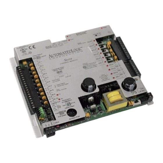
10 in this situation. Before setting or changing the address, make Input Resolution 10 bit A/D. sure the S6104’s power is off. The S6104 only reads the address when the module is turned Digital Outputs 6 digital outputs (Form on. -
Page 4: Power Wiring
The S6104 has two rotary switches for The S6104 has an operating range of 21.6VAC addressing: to 26.4VAC. If voltage measured at the module’s power input terminals is outside this • For WebCTRL systems, use the switches range, the module may not work properly. -
Page 5: Using The S6104 On An Arc156 Segment
ARC156. For a summary of the differences Network between ARCNET and ARC156, please refer to Before connecting the S6104 to the CMnet, be ARC156 CMnet Wiring Technical Instructions. sure the S6104’s power is off. Use the appropriate wire for network 1. -
Page 6: Communicating Through The Logistat Port Using Supervision
A ccess E IA-232 M ode Select P ort 2- Tx out Port 3- Rx in for communications when the S6104 is on an 5- Gnd TT L 1,6,8- +10V or floating ARC156 CMnet. M ode Select S w itch Table 2. -
Page 7: Communicating Through The Access Port Using Supervision
Port Using SuperVision enable communications through the LogiStat Port. When using SuperVision, you can connect a workstation or portable computer directly to the S6104 module using an APT and the Legacy ARC156 module’s Access Port (see Figure 6). This type Logi-... -
Page 8: Inputs
30 meters about wire length, gauge, and shielding. *Automated Logic Corporation recommends a specific wire to connect the S6104 to the LogiStat. This 22AWG solid copper wire is available from Magnum Cable NOTE On an ARC156 network segment, Corporation (part number A3LOGISTAT). - Page 9 T o M o d u le G ro u n d P o w e r S u p p ly Figure 8. Input Wiring 1. Be sure the S6104’s power is off before Open Energy Management Equipment wiring any inputs or outputs.
-
Page 10: Logistat Wiring
S6104” on page 12 for more information Mode Select about using a LogiStat sensor. Grip here 1. Be sure the S6104’s power is off before wiring a LogiStat to the LogiStat Port. 0-5VDC Thermistor/ 0-20mA 2. If using a LogiStat or LogiStat Plus, set the... - Page 11 86. Channel 81 corresponds to HOA Digital Outputs switch number one, channel 82 corresponds The S6104 has 6 digital outputs which can be to HOA switch two, and so on. connected to a maximum of 24 Volts AC/DC (see Figure 14). Each digital output is a dry An off status means the HOA switch is in Auto contact (rated at 3A maximum).
- Page 12 Status page in resistance). SuperVision** * use point type of HOA Status Feedback and point Be sure the S6104’s power is off before wiring number any inputs or outputs. Connect the output ** use channel numbers 81 - 86 wiring to the screw terminals on the module.
- Page 13 Number number, and minimum and maximum Digital DO 1 HOA Status present values for each point on the S6104. Digital DO 2 Select a physical point type from the point HOA Status type field and enter the number of the input or...
- Page 14 FB). mA or Volts § § 0 to 5V Digital The S6104 can store a single Function Block -17° to 213° F 0.00 15.88 in addition to the module driver. If any Thermistor -27° to 100.6° C 0.00...
- Page 15 SuperVision v2.6b or later, FB Link v2.7a or later, and the SLM NOTE Since the module is automatically module driver. The S6104 module using the formatted when you transfer memory, you SLM module driver can store a single FB.
- Page 16 LED data from the CMnet. Protection Digital Output Status - lights when the digital The S6104 module is protected by internal output is activated. solid state Polyswitches on the incoming power and network connections. These Analog Output Status - lights when the Polyswitches are not replaceable and will analog output is activated.
Need help?
Do you have a question about the S6104 and is the answer not in the manual?
Questions and answers