Nuova Simonelli prontobar Service Manual
Hide thumbs
Also See for prontobar:
- User handbook manual (72 pages) ,
- Handbook (39 pages) ,
- Maintenance plan (10 pages)
Chapters
Table of Contents

Subscribe to Our Youtube Channel
Related Manuals for Nuova Simonelli prontobar


Summary of Contents for Nuova Simonelli prontobar
- Page 1 SERVICE MANUAL...
- Page 2 SERVICE MANUAL Edition Date Changes on last versions 09/2012 Reorganization chapter 2. Functions and descriptions updates on chapter 07/2014 12-13. Chapter 9 updates. Edition 02 to 02/2014...
- Page 3 POURING GROUP GROUP MAINTENANCE GRINDERS BOILER TANKS SOLENOID VALVES ELECTRICAL COMPONENTS CAP PUMP AND WATERSTOP VALVE MILK CIRCUIT DOOR PROGRAMMING SPECIAL FEATURES ALARMS DAILY CLEANING AND MAINTENANCE BEVERAGE PREPARATION PRONTOBAR ROUTINE MAINTENANCE SCHEMATIC SPARE PART CATALOGUE Edition 02 to 02/2014...
-
Page 5: Table Of Contents
SERVICE MANUAL INDEX ANNUAL POURING GROUP INTRODUCTION ....1.1 MAINTENANCE..... . 4.9 DESCRIPTION. - Page 6 12.2 PROGRAMMING IN USER MODE..12.4 PRONTOBAR..... . . 18.3 12.2.1 Language selection..12.4 12.2.2...
-
Page 7: Index
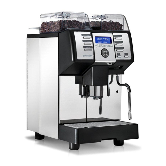
1.4.1 Machine identification ..1.8 with each other. PRONTOBAR makes up to 140 1.4.2 Transport ....1.8 espressos an 70 cappuccinos an hour. -
Page 8: Description
SERVICE MANUAL DESCRIPTION Fig. 1 Coffee bean holder cap Ground coffee conveyor hatch Milk flow adjusting tape Milk suction tube Control panel Control panel hatch opening / locking key Hot water wand Steam wand Pouring spout 10 Drop collecting tray grid 11 Water collecting tray 12 Coffee grounds drawer 13 Main switch (ON / OFF) -
Page 9: Keyboard Description (Standard Configuration)
SERVICE MANUAL KEYBOARD DESCRIPTION (Standard configuration) Fig. 2 Product’s dose key Programming keys Hot water key Steam key Decaffeinated coffee ON/OFF Washing Left grinder Milk button Edition 02 to 02/2014... -
Page 10: Safety Instruction
SERVICE MANUAL SAFETY INSTRUCTION Fig. 4 This book is an integral and essential part of the product and must be given to the user. Read this book care- fully. It provides important information concerning safety of installation, use and maintenance. Save it carefully for future reference. - Page 11 SERVICE MANUAL At the end of installation, the device is Fig. 6 switched on and taken to rated oper- ating conditions, leaving it in a state in which it is “ready for operation”. The device is then switched off and the whole hydraulic circuit is bled of the first lot of water in order to remove any initial impurities.
- Page 12 SERVICE MANUAL For installation, the qualified electri- To ensure that the machine is properly cian must fit an omnipolar switch in ventilated, place it with the ventilation accordance with the safety regula- side at a distance of 15 cm (5,9 in) from tions in force and with 3 (0,12) or more walls or other objects.
- Page 13 SERVICE MANUAL WARNING MECHANICAL HAZARD Never press and/or pull the safety switch. Fig. 11 CAUTION INFORMATION TO THE USERS Under the senses of art. 13 of Law Decree 25th July 2005, n. 151 “Implementation of the Directives/ Guidelines 2002/95/CE, 2002/96/CE and 2003/108/CE, concerning the reduction of the use of dangerous substances in electric and electronic equip-...
-
Page 14: Transport And Handling
SERVICE MANUAL TRANSPORT AND CAUTION HANDLING RISK OF IMPACT OR CRASHING 1.4.1 MACHINE IDENTIFICATION Before carrying out the following operation, the Always quote the machine serial number in all load must be checked to ensure that it is in the communications to the manufacturer, Nuova correct position and that, when the supports are Simonelli. -
Page 15: How To Install
SERVICE MANUAL HOW TO INSTALL INDEX TOOLS REQUIRED: HOW TO INSTALL....2.1 FIRST-TIME INSTALLATION ... 2.2 2.1.1 Weight and dimensions . -
Page 16: First-Time Installation
SERVICE MANUAL FIRST-TIME INSTALLATION Fig. 14 In this section the technical data of Prontobar are listed and first installation is safety guided. 2.1.1 WEIGHT AND DIMENSIONS Prontobar is 843.5 mm high, 400 mm wide and 607 mm deep. It’s net weight is 65 kilos. -
Page 17: Water Supply And Drainage
SERVICE MANUAL 2.1.3 WATER SUPPLY AND DRAIN- Fig. 17 WARNING The water hardness must be less then 4° - 6° fr (french degree). The chlorine content must not exceed 100mg per litre (0.00000361lb/cu in). Otherwise the conditions of guarantee of the machine will expire. -
Page 18: Water Tank Version
SERVICE MANUAL Drill the drainage tray to match the collector. Fig. 20 Clamp the drainage pipe to the drainage col- Fig. 21 lector. 00:23 Fig. 22 2.1.4 WATER TANK VERSION Fill the tank with demineralised water to the maximum level. LEVEL LEVEL WARNING... -
Page 19: Optional Direct Grounds Discharge
SERVICE MANUAL 2.1.5 OPTIONAL DIRECT GROUNDS Fig. 23 DISCHARGE Grounds discharge version, the service engi- neer must insert the conveyor funnel into the drawer and the discharge pipe into the relevant fitting under the machine. 00:34 2.1.6 REFILL COFFEE BOILER Fig. -
Page 20: Switching On/Off
SERVICE MANUAL Move down the group by pressing the arrow Fig. 26 down button and lubricate the bushes on top of the group with Teflon Spray. Move up the group by pressing the arrow up Fig. 27 button and lubricate with Teflon spray the two bushes on bottom of the group. -
Page 21: Accessories Box
SERVICE MANUAL NOTE When installing the machine for the first time or after water heater unit maintenance, press the button to dispense hot water before dis- pensing any coffee. Repeat this operation as required and until there is an even flow of water from the nozzle. -
Page 22: Filling The Coffee Bean Container
SERVICE MANUAL 2.1.10 FILLING THE COFFEE BEAN CONTAINER Use ONLY toasted coffee beans into the cof- Fig. 31 fee bean holder. Don’t insert caramelized, sugar coated or similar coated coffee beans, instant coffee or any other sugary beverages because they will harm the appliance. Listed below some possible configurations for the containers: and double dose and left container regular coffee beans for single and double doses. -
Page 23: Change Products Name
SERVICE MANUAL 2.1.12 CHANGE PRODUCTS NAME To change the beverage labels, lift the front Fig. 33 plastic cover with a normal screw driver using light pressure. With each machine are available different names, if more or different names are needed it’s possible to print the label using black background and font “cou- rier 24”, dim 45x70. -
Page 24: Beverages Programming
SERVICE MANUAL 2.2.2 BEVERAGES PROGRAMMING After language, press the arrow up key and insert the technical password that’s key 2 for five times 2-2-2-2-2 in sequence. Use arrow up key and select PROG DOSES pressing ENTER. Listed below some suggestions to start the settings of the machine. -
Page 25: Setting Programming
SERVICE MANUAL 2.2.3 SETTING PROGRAMMING It is the temperature of the water in the coffee boiler used to brew coffee, sug- gested value between 88 to 98; the temperature change the colour and the taste in the espresso, 90-92 for lighter colour cream, less bitterness more acidity (more COFFEE then 40% robusta percentage in the blend);... -
Page 26: Calibration
SERVICE MANUAL CALIBRATION The next installation phase involves setting the grind, the cappuccino air and the milk flow. These can also be made when the machines is turned on. 2.3.1 RIGHT GRINDER ADJUSTMENT To adjust grinding fineness on the right grinder, Fig. -
Page 27: Milk Temperature Adjustment
SERVICE MANUAL 2.3.3 MILK TEMPERATURE Fig. 38 ADJUSTMENT Insert the regulator on the pipe and adjust the screw on the right hand side of the machine. 01:44 Fig. 39 The default setting is to screen it completely closed, then open by two and a half turns. 01:52 Fig. -
Page 28: Autosteam Adjustment
SERVICE MANUAL Clockwise to reduce it. Fig. 42 We recommend performing this operation while actually pouring milk. 01:38 2.3.5 AUTOSTEAM ADJUSTMENT Fig. 43 The autosteam nozzle consist of a steninless steel outer pipe with an air inlet and a teflon inner pipe. - Page 29 SERVICE MANUAL In default setting, the teflon pipe covers half Fig. 46 the hole at the lower end of the steel pipe. 02:27 If the hole is covered, the foam is compact; Fig. 47 if the hole is open, the foam will have larger bubbles.
- Page 30 SERVICE MANUAL 2.16 Edition 02 to 02/2014...
-
Page 31: Pouring Group
SERVICE MANUAL POURING GROUP INDEX TOOLS REQUIRED: POURING GROUP ....3.1 POURING GROUP REMOVAL ..3.2 GROUP MOTOR REMOVAL... 3.5 HEATING ELEMENT AND PROBE REMOVAL . -
Page 32: Pouring Group Removal
SERVICE MANUAL Turn the machine off to access the dispensing Fig. 48 group, open the door, remove the grounds draw- er and remove the coffee hoppers by undoing the safety screw. 00:04 POURING GROUP REMOVAL Fig. 49 To access the pouring group, just open the door. The service engineer will need to: Turn the machine off. - Page 33 SERVICE MANUAL Remove the coffee nozzle; clip and top pis- Fig. 52 ton of the group. 00:27 Loosen the 4 screws on the front panel with Fig. 53 a philips screw driver. slide down the front panel. Remove the front panel from the front. 00:30 10 Remove the motor plug on top of the Fig.
- Page 34 SERVICE MANUAL 12 Unhook the water supply pipe by loosening Fig. 56 the fixing ring. Press the metal ring using a flat head screw- driver or a finger and pull the pipe. 00:44 13 Remove the covers of the grinder chutes. Fig.
-
Page 35: Group Motor Removal
SERVICE MANUAL GROUP MOTOR REMOVAL Fig. 59 The service engineer needs to: Remove the 2 screws at the top of the group using a philips screw driver. Slide out the motor. Remove the motor plug. This operation can be carried out with the group fitted to the machine and following the same 01:15 procedure. -
Page 36: Movement Screw And Bearings Removal
SERVICE MANUAL MOVEMENT SCREW AND Fig. 62 BEARINGS REMOVAL After removing the group from the machine (see par. 3.1) and the motor (see par. 3.2), you can: Release the worm screw by undoing the three 2.5 mm allen screws on top of the group support. - Page 37 SERVICE MANUAL When refitting these parts the service engi- Fig. 66 neers should take care to correctly position the first worm screw bearing, which has two washers with a grooved part inside and the balls in the centre. The next step is to insert the support (B) and then the second bearing (C).
-
Page 38: Infusion Chamber Removal
SERVICE MANUAL 10 Lubricate the bearings and bushing with Fig. 70 NUOVA SIMONELLI silicon lubricant. INFUSION Fig. 71 CHAMBER REMOVAL The brewing chamber can be reached by remov- ing the group, the motor and the worm screw: Pull out the two runners by removing two 3 mm allen screws and the two 2.5 mm on the... -
Page 39: Blade Ejector Worm Screw And Blade Ejector Removal
SERVICE MANUAL BLADE EJECTOR Fig. 74 WORM SCREW AND BLADE EJECTOR REMOVAL The blade ejector worm screw is located on the lower support bracket of the group. Once the pouring group has been removed (see par. 3.1); it is possible to take out the blade ejec- tor worm screw by removing the two screws on the base with a philips screw driver. - Page 40 SERVICE MANUAL Add a drop of loctite to the screw and tight- Fig. 78 en the 3 mm allen screw. 04:23 3.10 Edition 02 to 02/2014...
-
Page 41: Group Maintenance
SERVICE MANUAL GROUP MAINTENANCE INDEX TOOLS REQUIRED: GROUP MAINTENANCE ..4.1 SEMI-ANNUAL POURING GROUP MAINTENANCE ....4.2 4.1.1 Top piston . -
Page 42: Semi-Annual Pouring Group Maintenance
SERVICE MANUAL SEMI-ANNUAL POURING Fig. 79 GROUP MAINTENANCE It is recommended that the group has routine maintenance every 6 months or 25.000 pouring cycles. Follow the maintenance check list instruc- tion. Turn the machine off and remove the grounds drawer and the drip tray. Switch off the machine at the mains;... -
Page 43: Top Piston
SERVICE MANUAL 4.1.1 TOP PISTON Fig. 83 Remove the nozzle from the pipes. 00:34 Remove the upper piston cup. Fig. 84 00:37 Slide down the piston. Fig. 85 With the aid of a flat screw driver remove the screw security the piston shower. Clean the shower well with a damp cloth or soak it a while in hot water and pulicaff;... -
Page 44: Lower Piston
SERVICE MANUAL 4.1.2 LOWER PISTON Fig. 87 Press the down arrow and move the cham- ber to the bottom position. Remove the teflon pipe from the fitting: while holding the ring, pull on the delivery pipe. 00:54 With pliers, remove the bottom seeger from Fig. - Page 45 SERVICE MANUAL Slide out the piston out from the top. Fig. 91 01:20 Using a flathead screwdriver, take out the Fig. 92 screw securing the shower to the piston clean the shower with a damp cloth or leave to soak in hot water and pulicaff. shower dirty, replace...
- Page 46 SERVICE MANUAL 12 To reassemble, use teflon tape in the screw Fig. 95 thread. Add the new seal and lubricate with NUOVA SIMONELLI silicon grease. 01:42 13 Tighten the screw, but not fully. Fig. 96 01:44 14 Insert the lower piston and completely tight- Fig.
- Page 47 SERVICE MANUAL 16 Insert the seeger in the middle of the lower Fig. 99 piston shaft. 01:58 17 Press the up arrow key and insert the previ- Fig. 100 ously assembled spring. 02:07 Fig. 101 18 Press the down arrow to lower the chamber. Let go when the piston is about to enter the bottom support of the spring.
-
Page 48: Cleaning Runners And Lubrication
Lubricate the worm near the infusion chamber bushing with teflon spray. 00:54 Use NUOVA SIMONELLI silicon lubricants Fig. 105 on the screw worm bearings. 00:54 Moving the chamber up and down to remove Fig. -
Page 49: Annual Pouring Group
SERVICE MANUAL ANNUAL POURING GROUP Fig. 107 MAINTENANCE Every year or after 50.000 cycles the group should be replaced with a new or reconditioned one. For reconditioning follow the maintenance check list directions. 4.2.1 GROUP REMOVAL AND Fig. 108 CLEANING Unscrew the 4 allen screws and remove the top cover. - Page 50 SERVICE MANUAL Release the worm screw by undoing the Fig. 111 three 2.5 mm allen screws on top of the sup- port group. 03:32 The worm screw is at the back of the infu- Fig. 112 sion chamber. The bearings are part of the worm screw.
-
Page 51: Reassembling Pouring Group And Substitute Parts
SERVICE MANUAL The spring is secured to the blade ejector Fig. 115 shaft. 04:00 10 Wash everything with water and degreas- Fig. 116 ing soap. For a detailed overview of these actions, please refer to previous section of this chapter. 04:10 4.2.2 REASSEMBLING POURING... - Page 52 SERVICE MANUAL Blade expulsion busing. Fig. 119 Movement screw. 04:29 Blade expulsion spring. Fig. 120 04:33 The average time for annual maintenance is Fig. 121 about 2 hours and the replacement parts list is a follows: 02290021 02290019 03000069 05000737 0500744.1 08000085 04:36...
-
Page 53: Grinders
SERVICE MANUAL GRINDERS INDEX TOOLS REQUIRED: GRINDERS..... . 5.1 CONTAINERS ..... . . 5.2 GRINDER CHANGING . -
Page 54: Containers
SERVICE MANUAL CONTAINERS Fig. 122 The engineer needs to turn the key anti- clockwise. Open the front panel. 00:05 To remove the coffee containers, the service Fig. 123 engineer needs to close the two tabs that close the container. 00:19 Unscrew the safety screw and remove the Fig. -
Page 55: Grinder Changing
SERVICE MANUAL GRINDER CHANGING Fig. 125 To change the grinders, the engineer needs to remove (suction) the coffee beans in the grinder. Loose the adjustment worm screw that adjusts grinding fineness using the Phillips screwdriver, and then to slide the regulator from the top. -
Page 56: Changing The Condenser
SERVICE MANUAL Use the relevant screw to adjust grinding Fig. 129 fineness to obtain the desired coffee quality. 01:17 CHANGING Fig. 130 THE CONDENSER To access the condensers, the service engineer will have to: Switch off the machine. 01:21 Remove the left panel by taking out the two Fig. -
Page 57: Boiler Tanks
SERVICE MANUAL BOILER TANKS INDEX TOOLS REQUIRED: BOILER TANKS ....6.1 BOILER TANK AND FUSE COMPONENTS ..... . 6.3 DRAINING THE BOILER . - Page 58 Fig. 135 screw and loosen the bottom one on the inner panel. 00:22 Prontobar has two boilers, one for the coffee Fig. 136 and the other for the steam. The boilers hold 0.8 liters each. Both are stainless steel, insu- lated and use 1000W heating element each.
-
Page 59: Boiler Tank And Fuse
SERVICE MANUAL BOILER TANK AND FUSE Fig. 137 COMPONENTS The coffee boiler tank has: (A): Temperature probe (B): 16Bar expansion valve (C): Hot water solenoid valve connection fitting (C) (D): Safety thermostat (98 ° C - CSA version for the North American market only). 00:41 The steam boiler has: Fig. -
Page 60: Draining The Boiler
SERVICE MANUAL To replace the thermal fuse: Fig. 141 (1): Turn off Prontobar and unplug it. (2): Disconnect the fuse connections and slide out the fuse from the bottom. This operation takes place in the bottom part of the boiler tank. -
Page 61: Heating Element
SERVICE MANUAL Insert a pipe in the drain. Fig. 145 02:16 Open the connection on top of the boiler Fig. 146 tank to let air in so the water can drain. Wait for the boiler tank to empty completely. The procedure is the same for the steam boiler tank. - Page 62 SERVICE MANUAL The service engineer unfastens: Fig. 149 The heating element power cable. 02:56 The teflon water inlet pipe. Fig. 150 02:59 The electrical connections for the coffee Fig. 151 solenoid exhaust. 03:02 8-9 Remove the ground connection, then free the Fig.
- Page 63 SERVICE MANUAL 11-12 Open the front panel by loosening the 4 Fig. 153 screws. 03:19 13-14 Remove the Teflon pipe, and with a Fig. 154 Phillips screwdriver, unscrew the two screws holding the boiler tank. 03:27 15 Remove the boiler from behind. Fig.
- Page 64 SERVICE MANUAL 17 After replacing the coffee boiler tank, the Fig. 157 boiler must be filled using the refill function on the special manual handling function menu. 18 To enter manual handling, turn off the machine’s main switch, pressing and hold- ing the up / down arrow keys.
-
Page 65: Solenoid Valves
SERVICE MANUAL SOLENOID VALVES INDEX TOOLS REQUIRED: SOLENOID VALVES ....7.1 HOW TO ACCESS ....7.2 REMOVING THE SOLENOID VALVE. -
Page 66: How To Access
SERVICE MANUAL HOW TO ACCESS Fig. 161 The solenoid group is accessible from the right side of the machine. Open the door. 00:01 Remove the grounds drawer. Fig. 162 00:06 Undo the two screws on the front right panel. Fig. 163 Remove the milk pipe temperature control. - Page 67 SERVICE MANUAL Starting at the top right corner of the sole- Fig. 165 noid the valves are: Steam for milk frother Steam for manual wand Hot water for manual wand Hot water bypass (optional) Self-levelling. 00:32 From top left, the valves are: Fig.
-
Page 68: Removing The Solenoid Valve
SERVICE MANUAL REMOVING THE SOLENOID Fig. 168 VALVE This must be done with the machine switched off and the boiler cold. To access the service engineer must: Remove the right panel. 00:58 Remove the condenser exhaust pipe clip Fig. 169 and pipe (for frother solenoid valve only;... - Page 69 SERVICE MANUAL With a 13 wrench, turn the nut and remove Fig. 172 the copper steam pipe. 01:21 With a Phillips screwdriver, undo the two Fig. 173 screws that hold the solenoid. 01:28 When replacing the solenoid, ensure proper Fig. 174 positioning of the joints.
-
Page 70: Coffee Solenoid Valve
SERVICE MANUAL COFFEE SOLENOID VALVE Fig. 175 To replace the coffee solenoid valve: Remove the front panel by loosing the 4 screws. 01:44 Remove the Teflon pipe by holding the ring. Fig. 176 Remove the exhaust pipe clip and the coffee Fig. - Page 71 SERVICE MANUAL With 12 and 13 wrench, remove the copper Fig. 179 pipe connecting the solenoid valve and the coffee boiler tank. 01:59 Remove and replace the solenoid, making Fig. 180 sure the fittings are correctly positioned. 02:06 Edition 02 to 02/2014...
- Page 72 SERVICE MANUAL Edition 02 to 02/2014...
-
Page 73: Electrical Components
SERVICE MANUAL ELECTRICAL COMPONENTS INDEX TOOLS REQUIRED: ELECTRICAL COMPONENTS..8.1 HOW TO ACCESS ....8.2 TRANSFORMER ..... 8.5 CAPACITOR. -
Page 74: How To Access
SERVICE MANUAL HOW TO ACCESS Fig. 181 Make sure the machine is turned off. Using a Phillips screwdriver, undo the two screws at the top and the two screws on the front left side panel. 00:07 The electrical components are: Fig. - Page 75 SERVICE MANUAL (E) Drawer magnetic reader. Fig. 185 00:25 Two grinder capacitors Fig. 186 (one for the single grinder version). 00:27 (G) Microswitch for tank presence. Fig. 187 00:32 (H) Power Transformer for control unit and Fig. 188 group motor. 00:33 Edition 02 to 02/2014...
- Page 76 SERVICE MANUAL (I) Left grinder connector. Fig. 189 00:36 (J) The electric control unit. Fig. 190 00:39 Edition 02 to 02/2014...
-
Page 77: Transformer
SERVICE MANUAL TRANSFORMER Fig. 191 To replace the transformer, disconnect the input. 00:46 Disconnect the output connectors with flat Fig. 192 screwdriver to undo the screws. 00:45 With a 5 mm allen key unscrew the screw to Fig. 193 remove the transformer. 00:42 Edition 02 to 02/2014... -
Page 78: Capacitor
SERVICE MANUAL CAPACITOR Fig. 194 To replace the capacitor, switch off the machine with the main switch. Remove the two cables. 00:51 Use a 13 wrench to unscrew the nut. Fig. 195 00:33 When replacing the capacitor, always check Fig. 196 the label values. -
Page 79: Electronic Control Unit
SERVICE MANUAL ELECTRONIC CONTROL Fig. 197 UNIT To remove the electronic control unit, dis- connect all connecting wires and four lock- ing screws on the frame. 01:10 At the top of the unit are: Fig. 198 Fuse [6.3 A] Input power transformer and motor output 01:12 Motor encoder... - Page 80 SERVICE MANUAL At the bottom of the unit are: Fig. 201 Clock battery On the eprom is indicated the release of the software loaded Door and bottom drawer microswitch connector Relay and solenoid valves, grinders and pump connectors. 01:42 Dip switch to configure the machine (see Fig.
- Page 81 SERVICE MANUAL For installation, follow the wiring diagram Fig. 205 (see chap. 18 for complete diagram). 01:32 All connections are shown in the diagram Fig. 206 inside in the left panel. 02:19 Edition 02 to 02/2014...
- Page 82 SERVICE MANUAL 8.10 Edition 02 to 02/2014...
-
Page 83: Cap Pump And Waterstop
SERVICE MANUAL CAP PUMP AND WATERSTOP VALVE INDEX TOOLS REQUIRED: CAP PUMP AND WATERSTOP VALVE ......9.1 HOW TO ACCESS . -
Page 84: How To Access
SERVICE MANUAL HOW TO ACCESS Fig. 207 To access the service engineer must: Turn off the machine. 00:06 Remove the back panel by undoing the two Fig. 208 screws with a Phillips screwdriver. 00:08 In the tank version, remove the tank. Fig. - Page 85 SERVICE MANUAL Remove the left side panel. Fig. 211 00:18 Please note that the two versions of the Fig. 212 machine presents some differences: In the tank version are: (A) Tank water level sensor (Fig. 211). (B) Water tank connection (Fig. 212). 00:22 Fig.
-
Page 86: How To Replace The Flowmeter
SERVICE MANUAL Please note that the two versions of the Fig. 214 machine presents some differences: In the tank version are: On the bottom panel both the versions are equipped with a metal high pressure flow- meter (C). The direct connection version also has a water stop valve used to control the input water (D). - Page 87 SERVICE MANUAL With a 12 wrench remove the inlet and outlet Fig. 217 teflon pipes. When replacing the flowmeter, see the arrows Fig. 218 to ensure that the input and output are cor- rectly connected. WARNING Please pay attention when reassembling the retain valve.
-
Page 88: Pump Removal
SERVICE MANUAL PUMP REMOVAL Turn the machine off and unplug it, open the rear panel on the right side, remove the tank and open the boiler protection panel. In the tank version, remove the tank. Remove the input and output pipes from the Fig. - Page 89 SERVICE MANUAL Disconnect the capacitor undoing the screw Fig. 221 with a phillips screwdriver. With a phillips screwdriver, undo the screw Fig. 222 clump, disconnect the wires and slide out the motor from the right side of the machine. Fig. 223 Edition 02 to 02/2014...
-
Page 90: Pump Pressure Setting
SERVICE MANUAL PUMP PRESSURE SETTING Fig. 224 Whenever the pump is replaced or special main- tenance is required, check the pump pressure. Open the door turning the key anticlockwise. 00:04 Remove the grounds drawer and the drip Fig. 225 tray. 00:10 Slide out the nozzle. - Page 91 SERVICE MANUAL Slide down and remove the front panel. Fig. 228 Unhook the water supply pipe by pressing the fixing ring with a finger or using a flat head screw driver. 00:44 Put only the grounds drawer in its position to close the circuit of the magnetic sensor for “drawer out”...
-
Page 92: Replace Waterstop Valve
SERVICE MANUAL REPLACE WATERSTOP Fig. 230 VALVE To replace the waterstop valve in the direct con- nection version: Turn the machine off and unplug it. Open the rear panel and remove the aquas- top outlet pipe, pressing the ring. 02:11 Remove the faston connections. -
Page 93: Milk Circuit
SERVICE MANUAL MILK CIRCUIT INDEX TOOLS REQUIRED: MILK CIRCUIT ....10.1 10.1 CAPPUCCINO MAKER AND NOZZLE ..... . 10.2 10.2 AUTO WASHING AND AIR SOLENOIDS VALVES . -
Page 94: And Nozzle
SERVICE MANUAL 10.1 CAPPUCCINO MAKER AND Fig. 234 NOZZLE Turn off the machine and open the door. 00:08 Inside the pouring nozzle are: Fig. 235 A Cappuccino maker, B Steam inlet pipe on top, C Milk inlet pipe on the right (white silicone), D the blue inner pipe is for the coffee, E (OPTIONAL) The blue exterior one is to add optional hot water. -
Page 95: Auto Washing And Air Solenoids Valves
SERVICE MANUAL 10.2 AUTO WASHING AND AIR Fig. 238 SOLENOIDS VALVES To access open the right panel undoing the two screws in top and the two screws in the front. The autowashing and air valves are located in the right part of the machine. 00:43 10.2.1 AUTOWASHING SOLENOID... -
Page 96: Air Solenoid Valve
SERVICE MANUAL When reassembling, ensure the fittings com- Fig. 242 ply with the entry and exit arrows. 01:06 10.2.2 AIR SOLENOID VALVE Fig. 243 To remove the air solenoid, disconnect elec- trical connections from the coil. 01:13 Remove the clip and the silicon pipe. Fig. -
Page 97: Air Regulator
SERVICE MANUAL 10.3 AIR REGULATOR Fig. 246 The air regulator is behind the front panel and is connected to the air solenoid valve. 01:38 10.4 MILK PIPE Fig. 247 Whenever the right side panel is crened, verify that there are no blockages in the milk pipe. 01:49 10.5 Edition 02 to 02/2014... - Page 98 SERVICE MANUAL 10.6 Edition 02 to 02/2014...
-
Page 99: Door
SERVICE MANUAL DOOR INDEX TOOLS REQUIRED: DOOR......11.1 11.1 DISPLAY AND KEYBOARD... 11.2 11.2 NOZZLE . -
Page 100: Display And Keyboard
SERVICE MANUAL 11.1 DISPLAY AND KEYBOARD Fig. 248 The front of the machine are located: A Display B Keyboard with six drinks keys C Hot water key D Steam key E 4 multifunction keys 00:06 F Coffee nozzle Fig. 249 G Lock key H Hot water wand F Steam wand... - Page 101 SERVICE MANUAL Disconnect the three connectors: Fig. 252 A Keyboard B Display C USB 00:24 Undo the six screws on the keypad display Fig. 253 cover. The seventh screw is near the display con- nector. Under the protection. 00:33 Remove the cover. Fig.
-
Page 102: Nozzle
SERVICE MANUAL To change the display, remove the 4 screws. Fig. 256 00:42 Undo the two nuts to remove the USB pro- Fig. 257 gramming board. 00:51 10 The micro switch connections are inside the Fig. 258 door. 01:02 11.2 NOZZLE Fig. - Page 103 SERVICE MANUAL To adjust the nozzle angle turn the two 3mm Fig. 260 allen screws and tighten the screws with the nozzle correctly in place. This is useful to reduce the flow equally in the two nozzles. Remove the cappuccino maker. Fig.
-
Page 104: Botton Drawer
SERVICE MANUAL 11.3 BOTTON DRAWER Fig. 264 Remove the bottom drawer and tray. On the left of the tray is the relevant micro. 01:36 11.4 STEAM AND HOT WATER Fig. 265 NOZZLES 2° Open the door, remove the clip and slide down the water and steam nozzles. -
Page 105: Beverage Labels
SERVICE MANUAL 11.5 BEVERAGE LABELS Fig. 267 To change the beverage labels, lift the front plastic cover with a normal screwdriver using light pressure. 01:50 Remove the cover and replace the drink Fig. 268 label. 02:10 11.7 Edition 02 to 02/2014... - Page 106 SERVICE MANUAL 11.8 Edition 02 to 02/2014...
- Page 107 SERVICE MANUAL PROGRAMMING INDEX PROGRAMMING ....12.1 12.1 INTRODUCTION ....12.3 12.2 PROGRAMMING IN USER MODE.
- Page 108 SERVICE MANUAL right arrow EXIT 22222 COFFE TEMPERATURE O - 80 max 105 C° BUTTON 1-6 BUTTON 1 select grinder STEAM TEMPERATURE O -min 80 max 150 C° GROUP TEMPERATURE O -min 50 max 105 C° 2 COFFEE MAINTEINANCE 0:500:30000 BUTTON 2 select grinder GROUNDS NUMBER...
- Page 109 SERVICE MANUAL 12.1 INTRODUCTION Fig. 269 When the machine is turned on, the software release "A" is displayed as well ad the position of the 4 dip switches for configuring the machine "B". When the number is displayed the related dipswich is position ON.
-
Page 110: Programming In User Mode
SERVICE MANUAL 12.2 PROGRAMMING IN USER Fig. 272 MODE 12.2.1 LANGUAGE SELECTION To enter the menu press ENTER for 5 seconds; "SELECT LANGUAGE" appears: this is the only function in user mode. 00:34 Fig. 273 Press the ENTER key to enter the sub- menu. -
Page 111: Read Beverages Counters
SERVICE MANUAL 12.2.2 READ BEVERAGES Fig. 276 COUNTERS To access the beverages counters page switch off the machine until screen shows “MACHINE OFF”. Press the keys number 1 and 4 together as in the image (276). Accessing to the page by this way do not allow the client to zero the counters. -
Page 112: Program Doses
SERVICE MANUAL Fig. 280 With the up and down arrow keys, you can see: All six drinks Tea/hot water Steam Cleaning/wash counter Litres total Drink total 01:32 12.3.2 PROGRAM DOSES Fig. 281 From the service engineer mode menu, press: A The down arrow key to select the "program doses"... - Page 113 SERVICE MANUAL It is possible to select the beverage by Fig. 283 pressing the keys: COFFEE: coffee cycle 2 COFFEE: coffee cycle DISABLE : key disabled MILK + COFFEE: milk cycle + coffee cycle CAFFELLATTE: milk cycle + coffee cycle together COFFEE + MILK: coffee cycle + milk MACCHIATO: milk cycle + pause (few sec-...
-
Page 114: Functions Description
SERVICE MANUAL COFFEE and 2 COFFEE beverage functions. GRIND TIME (used to set the grinding time GRIND TIME (used to set the grinding time of the right-hand grinder) of the right-hand grinder) GRIND TIME (used to set the grinding time GRIND TIME (used to set the grinding time of the left-hand grinder) - Page 115 SERVICE MANUAL Press ENTER to confirm settings. Pressing ENTER it is possible to enter the sub menu; the keys are used WASH (Automatic milk tube wash): to increase/reduce grinding time. Press It is possible to set the cold water washing time ENTER to confirm settings.
-
Page 116: Setting
SERVICE MANUAL 12.3.4 SETTING Fig. 285 From the service engineer mode menu, press: A The down arrow key to select the "setting" sub-menu. B The ENTER key to go into the sub-menu. The programs available are: Coffee temperature Steam temperature 03:26 Group temperature Maintenance... - Page 117 SERVICE MANUAL GROUP TEMPERATURE Fig. 288 The temperature of the delivery group can be set. By pressing the ENTER key the submenu can be accessed; keys let you increase/ diminish the temperature of the water in the coffee boiler (min. 50°C max. 105°C.) Press ENTER to confirm settings.
- Page 118 SERVICE MANUAL RINSE GROUP Fig. 292 It can be set to ON/OFF. If set on ON, the machine will carry out a rinsing cycle of the group 20 minutes after the last cycle if the machine is not being used. By pressing the ENTER key the submenu can be accessed;...
- Page 119 SERVICE MANUAL Pressing ENTER it is possible to enter the sub menu and the display will read as follows: SUNDAY DAY OFF keys are used to view the settings for each day of the week. Press ENTER to set the required day of the week; the keys are used to select the hour and minutes for switching on and the hour and minutes for switching off.
- Page 120 SERVICE MANUAL ENERGY SAVING Fig. 296 This is used to set the time after which the machine enables the energy-saving device, while still keeping the water tank at working tempera- ture. 04:47 Press the ENTER key to access the sub- menu.
- Page 121 Press RESET to quit the submenu. 05:06 DE-SCALING Fig. 301 (Prontobar version with Tank only) Press the ENTER key to access the submenu. The first message to appear concerns the pos- sibility to set water hardness. 05:12 12.15...
-
Page 122: Setting Water Hardness
SERVICE MANUAL Press the keys to enable (YES) / deactivate (NO) cleaning at the end of service. WaterHardness ° FR keys can be used to select one of the following two functions: Start Cycle? Back to the main menu and to confirm the tem- perature programmed. -
Page 123: De-Scaling Cycle
SERVICE MANUAL Press the ENTER key to return to the main menu and save the setting to memory. Press the RESET key to return to the main menu without saving the setting to memory. The following table shows the correspondence between the hardness setting and the number of litres of water consumed after which the “DE-SCALE”... - Page 124 SERVICE MANUAL Note: Use at least 2 (0.52 gal) litres of solu- tion. Start Cycle? tion from the tank and at the same time, to expel hot water from the nozzle. Please Wait Once it has sucked up the first litre of solution, the machine will stop for five minutes and then it will start to suck up another litre of solution.
- Page 125 SERVICE MANUAL read as follows: Rinse Press Wait (0,53 gal) taken from the container, the dis- play will again read: Rinse Press Enter Press the ENTER key again for the machine to start the second stage of the rinse cycle, taking a further 2 litres(0,53 gal) on board from the con- tainer.
- Page 126 SERVICE MANUAL CHANGE PASSWORD? Fig. 302 It is possible to set a new password to access the programmable functions in technical mode. Pressing ENTER it is possible to enter the sub menu. 05:16 Enter the old password: Fig. 303 OLD PASSWORD XXXX Enter the new password using a combination of 4 keys: NEW PASSWORD XXXX...
- Page 127 SERVICE MANUAL SPECIAL FEATURES INDEX SPECIAL FEATURES ... 13.1 13.1 MANUAL HANDLING....13.2 13.2 DATA RESET ..... . . 13.3 13.3 WASH COUNTER RESET .
- Page 128 SERVICE MANUAL 13.1 MANUAL HANDLING Fig. 304 To enter manual handling: Turn off the machine at the main switch. 00:02 Press both the up (A) and down (B) arrow Fig. 305 keys, and switch on the machine holding the two buttons pressed, until the display shows "manual movement".
-
Page 129: Data Reset
SERVICE MANUAL To exit the menu, switch off the machine at the Fig. 308 main switch. 00:34 13.2 DATA RESET Fig. 309 With this function, it is possible to remove incor- rect operating data and return to default pro- gramming valves. Turn off the machine at the main switch. -
Page 130: Counter Reset Filters
13.5 EXPORT SETTINGS TO USB MEMORY STICK It’s possible to set a machine and copy the set- tings to other Prontobar, in order to obtain con- sistent products. Empty a memory stick. Switch off the Prontobar machine (the dis- play shows OFF). -
Page 131: Software Update By Usb Memory Stick
It’s better to use an empty memory stick to avoid any kind of mistake. Switch off the Prontobar machine (the dis- play shows OFF). Open the front door and insert the USB memory stick on the back of the door. -
Page 132: Machine Configuration
SERVICE MANUAL 13.8 MACHINE CONFIGURATION Fig. 313 During the camp test, after turning the machine on, the display will show the layout of the 4 micro switches. The second line will show the number of the micro if it is in on position; in the off posi- tion, the number is not displayed. - Page 133 SERVICE MANUAL 14 . ALARMS INDEX ALARMS ..... 14.1 14.1 ALARM THAT BLOCK MACHINE FUNCTION......14.2 14.2 MACHINE FUNCTIONS MESSAGES.
- Page 134 SERVICE MANUAL 14.1 ALARM THAT BLOCK MACHINE FUNCTION. DISPLAY CAUSA EFFECT SOLUTION PAR. Grounds drawer Keys delivering cof- Pull out the grounds full. The num- fee based drinks are drawer and empty it ber of coffee blocked. into a garbage bag. grounds in the Put the drawer back DRAWER...
- Page 135 SERVICE MANUAL DISPLAY CAUSA EFFECT SOLUTION PAR. The group can Coffee will not Check if the upper not close the be delivered and an piston enters free brewing cham- ejection cycle will brewing ber with the be effected. chamber when it upper piston.
- Page 136 SERVICE MANUAL DISPLAY CAUSA EFFECT SOLUTION PAR. There’s no more The machine func- Switch water in the tions are blocked. machine with tank. the main switch, remove and refill the tank, switch on the machine. Check the posi- tion of the water REFILL WATER level magnetic...
- Page 137 SERVICE MANUAL 14.2 MACHINE FUNCTIONS MESSAGES. DISPLAY CAUSA EFFECT SOLUTION PAR. The volume The delivery will Check the flowmeter counter will continue for up to connection or change not send any 60 seconds or as impulses to the long as any of the control unit for 5 coffee based drink seconds.
- Page 138 SERVICE MANUAL DISPLAY CAUSA EFFECT SOLUTION PAR. One of the boil- The message Switch OFF the ers or the group remain in the dis- machine with the has not reached play until the two main switch and the temperature boilers and the switch ON hold- set.
- Page 139 SERVICE MANUAL DAILY CLEANING AND MAINTENANCE INDEX TOOLS REQUIRED: DAILY CLEANING AND MAINTENANCE....15.1 15.1 INTRODUCTION ....15.2 15.2 CHAMBER CLEANING BRUSH .
- Page 140 SERVICE MANUAL 15.1 INTRODUCTION Before carrying out any exterior cleaning, set the machine to "O" power (I.E. machines switched off). 15.2 CHAMBER CLEANING Fig. 315 BRUSH Open the door. 00:09 Slide out the grounds drawer. Fig. 316 00:13 Using a brush, clean any coffee buildup or Fig.
- Page 141 To wash the machine, switch it on and proceed as follows: Place a container filled of water alongside. Insert the suction tube. 00:42 Add the NUOVA SIMONELLI specific clean- Fig. 320 er, pulimilk. 00:48 Press and hold down the "clean" key for Fig.
- Page 142 SERVICE MANUAL Insert the NUOVA SIMONELLI detergent tab, Fig. 322 pulycaff, inside the pouring chamber. 01:02 Press the "clean" button, the display will Fig. 323 show: CLEAN The dose keys are disabled during washing. 01:02 At the end of the wash cycle, the display...
- Page 143 SERVICE MANUAL The machine will carry out a rinse cycle and Fig. 325 the display shows: RINSE 01:31 10 After the washing cycle is finished, the Fig. 326 machine will return to the state: SELECTED PRODUCT 01:35 15.5 POURING NOZZLE WASH Fig.
- Page 144 SERVICE MANUAL Slide out the milk frother and pull out the cof- Fig. 329 fee outlet cup and remove it. 01:48 Then divide the cappuccino maker in four Fig. 330 parts and wash them all carefully in cold water. 01:58 To refit the parts, follow the instructions on Fig.
- Page 145 SERVICE MANUAL BEVERAGE PREPARATION 16.1 Edition 02 to 02/2014...
- Page 146 SERVICE MANUAL Beverage preparation is extremely simple. Fig. 332 All the barista needs to do is: Fill the containers with coffee beans. WARNING Pour ONLY toasted coffee beans into the coffee bean holder. Any other kind of coffee, for example ground coffee, will damage the coffee grinder.
- Page 147 SERVICE MANUAL 4.2 Put the appropriate measure of decaf- Fig. 336 feinated coffee in the chute, 4.3 Close the door. 00:43 4.4 Press the "deca" button, Fig. 337 4.5 Choose the required beverage. 00:49 The grinder setting is very important to get- Fig.
- Page 148 SERVICE MANUAL For a creamy and fragrant cappuccino, it is Fig. 339 important to have the right temperature and AIR REGULATOR amount of air in the cappuccino maker. Too much air will affect the result in the cup with an inconstant flow of milk. When the temperature is too high and large bubbles appear, this means the air flow needs reduc- ing.
- Page 149 SERVICE MANUAL PRONTOBAR ROUTINE MAINTENANCE INDEX TOOLS REQUIRED: PRONTOBAR ROUTINE MAINTENANCE....17.1 17.1 3 MONTHS MAINTENANCE OR 12.500 CYCLES (RECOMMENDED) ..17.2 17.2...
- Page 150 12.3.2 Check milk foam quality and adjust if necessary Clean the movement guides 07300566 4.1.3 Lubricate the movement screw bearings 08000071 with Nuova Simonelli silicon 4.1.3 grease Lubricate with Teflon spray the bushes and the movement screw near the plastic 4.1.3...
- Page 151 Check the position of the coffee chutes and adjust if necessary Clean the movement guides 07300566 4.1.3 Lubricate the movement screw bearings 08000071 with Nuova Simonelli silicon 4.1.3 grease Lubricate with Teflon spray the bushes and the movement screw near the plastic 4.1.3...
- Page 152 SERVICE MANUAL 17.3 ANNUALLY MAINTENANCE OR 50.000 CYCLES (MANDATORY) STEPS SEE PAR. Absolute Total Cycle _______________ (record) 12.3.1 Washing cycles _______________ (record) 12.3.1 Check water hardness (as per test strip) _______ °F Change water softener filter if necessary NOTE: The water hardness must be less then 6° fr (french degree); the chlorine content must not exceed 100mg per litre (0.00000361lb/cu in);...
- Page 153 Plastic movement nut 0500744.1 All other wear and tear component Clean the movement guides 07300566 4.1.3 Lubricate the movement screw bearings 08000071 with Nuova Simonelli silicon 4.1.3 grease Lubricate with Teflon spray the bushes and the movement screw near the plastic 4.1.3...
- Page 154 SERVICE MANUAL 17.6 Edition 02 to 02/2014...
- Page 155 SERVICE MANUAL SCHEMATIC 18.1 HYDRAULIC SCHEMATIC PRONTOBAR 18.1 Edition 02 to 02/2014...
- Page 156 SERVICE MANUAL 18.2 HYDRAULIC SCHEMATIC PRONTOBAR (WATER TANK VERSION) 18.2 Edition 02 to 02/2014...
- Page 157 SERVICE MANUAL 18.3 ELECTRICAL SCHEMATIC PRONTOBAR 18.3 Edition 02 to 02/2014...
- Page 158 SERVICE MANUAL 18.4 Edition 02 to 02/2014...
- Page 159 SERVICE MANUAL SPARE PART CATALOGUE INDEX SPARE PART CATALOGUE ..19.1 19.1 CABINET PARTS....19.2 19.2 TANK FRAME PARTS....19.3 19.3 BOILER PARTS .
-
Page 160: Cabinet Parts
SERVICE MANUAL 19.1 CABINET PARTS 01000228 01000226 05000753 05002108 05000753 05000758 03001642 05000110 05002106 01000224 03001678 04900908 05002110 05002116 03001696 05002122 01000225 00000181 05340020 03001640 04900912 04900902 03001688 01000015 03001695 05002120 05002118 (KIT) 11600001.B - L=150 05002124 05002130 03001648 05002148 980100000001120000 * 04000313 02000005... -
Page 161: Tank Frame Parts
SERVICE MANUAL 19.2 TANK FRAME PARTS 98200000000022 03001656 03001658 03001653 - CSA 03001654 03001662 03001674 03001652 02280018 05000751 03001670 01000155 04000310 04000312.A 04000565 05000746 - 7 PZ 05000759 05000530 07300545 05000746 - 3PZ 01000162 03001676 05000083 04200063 03001668 05080037 03001660 01000162 03001666 05002228... -
Page 162: Boiler Parts
SERVICE MANUAL 19.3 BOILER PARTS 05000012 04000714 - CSA 04900775.1 01000220 98120001 07300128 07300251 11600002 - L=140 03000004 - CSA 11600002 - L=40 09500001 - CSA 04000198 98030308 - 230V 11600002 - L=375 03001670 01000218 01000222 84003003 07300544 04000129 07300233 09500015 (184°C) 11600001.W - L=450 07300101... -
Page 163: Pouring Unit Group Parts
SERVICE MANUAL 19.4 POURING UNIT GROUP PARTS 04600014 00300034 07300265 00300034 00000089 07300662 00000011 08000071 08000083 00000165 03001686 05000762 07300562 40000003 02290021 00000148 08000071 03000069 08000047 03001620 00300022 00000011 00000200 05002144 00000150 07300616 07300257 00000113 03001684.T 00300022 03000069 05000743 00300019 00000011 00000113 98040000000064... -
Page 164: Grinders Parts
SERVICE MANUAL 19.5 GRINDERS PARTS 05002114 98140000000030 98140000000032 00000169 15050011 98010000000118 15000040 05000029 05002113 84005001 98140000000033 98140000000031 15800045 00000134 84005001 15800038 02290025 02290025 15800045 00000134 00000134 08000038 15800038 15800045 08000038 00000134 07300522 15800045 08000038 00000044 00000119 00000044 01000160 85060006 03001664 00000119 00000119 85060006... -
Page 165: Electronic & Electric Parts
00000060 05002227 00000164 05002236 04060015 CSA Elenco parti CODICE DESCRIZIONE 04000704 CAVO INTERRUTTORE - MORSETTO PRONTOBAR 2009 04000604 SUPPLEMENTO EV ENTRATA MICROBAR 2004 ACQUASTOP 04000700 IMPIANTO ELETTRICO PRONTOBAR 2009 Elenco parti CODICE DESCRIZIONE 04000706 CAVI BASSA TENSIONE (MOTORE - LIVELLO CALDAIE + TANICA) - Page 166 SERVICE MANUAL 19.7 COMPONENT PUMP – STEAM – HOT WATER AUTOSTEAM WAND STEAM WAND 08000003 08000003 08000003 08000003 00300001 00000089 00300001 00000089 00300001 07300255 00300001 07300255 00000073 03001666 03001666 00000073 00000073 00000073 00000192 00000192 07300248 00000089 02280037 07300248 07300248 07300248 00000089 08000027 02280037...
-
Page 167: Hydraulic Component
SERVICE MANUAL 19.8 HYDRAULIC COMPONENT 04100058 - 208-240V 60HZ CSA 07300005 04100042 - 230V 50/60Hz CE 11600001.W - L=450 04100068 - 208/240v 60hz CSA 04100070 - 208/240v 60Hz CSA 04100054 - 230V 50-60HZ CE 04100042 - 230V 50/60Hz CE 07300001 07300005 11600001,R - L=500 03001672... - Page 168 03001684.T LAMIERA GR. EROGAZ. PRONTOBAR TEFLONATA TEFLON DISPENSING GROUP PANEL - PRONTOBAR 03001686 PIASTRA ADATTAMENTO MOTORE GR.EROGAZIONE PRONTOBAR DISPENSING GROUP MOTOR ADAPTATION PLATE - PRONTOBAR 03001690 RETINA A FILO INOX PIANO LAV. PRONTOBAR STAINLESS STEEL MESH, WORK SURFACE - PRONTOBAR 19.10...
- Page 169 STAINLESS STEEL COVER DISPENSER SPOUT - PRONTOBAR 03001695 INSERTO INOX DX PORTA FRONTALE PRONTOBAR 2013 SS FRONT DOOR RIGHT INSERT - PRONTOBAR 03001696 INSERTO INOX SX PORTA FRONTALE PRONTOBAR 2013 +LOGO LSS FRONT DOOR LEFT INSERT - PRONTOBAR 04000129 COPRIFASTON F NERO FASTON COVER CFF63 04000198 PRESA LAMELLARE M 6.3 d4.2 45...
- Page 170 DREGS DROWER ASSEMBLY (DIRECT DRAIN) - PRONTOBAR 9801000000011400001 ASSIEME VASCHETTA RACC.ACQUA PRONTOBAR DRIP TRAY ASSEMBLY PRONTOBAR 9801000000011400002 ASSIEME VASCHETTA RACC.ACQUA PRONTOBAR SCARICO DIRE DRIP TRAY ASSEMBLY (DIRECT DRAIN) - PRONTOBAR EMBLY - PRONTOBAR 98030308 CALDAIA SALD. ACCIAIO Aisi316 MICROBAR 08 230V 1000W...
- Page 171 98140000000033 ASS. SCIVOLO PER MACININO SX PRONTOBAR LEFT ASSEMBLY GRINDER CHUTE 98160000000142 ASSIEME SONDA + RESISTENZA GR.EROGAZIONE PRONTOBAR ASSEMBLY TEMP PROBE + CARTRIDGE HEATING FOR GROUP PRONTOBAR 98200000000022 ASS. TANICA ACQUA 5LT CON GALLEGGIANTE WATER CONTAINER COMPLETE 5 LITRES AWER ASSEMBLI - PRONTOBAR CE...
- Page 172 SERVICE MANUAL 19.14 Edition 02 to 02/2014...
- Page 173 SERVICE MANUAL UPDATES Edition 02 to 02/2014 19.15...
- Page 174 SERVICE MANUAL 19.16 Edition 02 to 02/2014...
- Page 176 Tel. +39.0733.9501 Fax +39.0733-950242 www.nuovasimonelli.it E-mail: n.simonelli@nuovasimonelli.it Nuova Distribution Centre LLC 6940Salashan PKWY BLDG A 98248 Ferdale, Tel. +1.360.3662226 Fax +1.3603664015 videoconf.+1.360.3188595 www.nuovasimonelli.it info@nuovasimonelli.com Graphics by: TYPE ENGINEERING S.r.l La Nuova Simonelli si riserva di apportare tutte le modifiche ritenute necessarie.
Need help?
Do you have a question about the prontobar and is the answer not in the manual?
Questions and answers