aci DLP Series Installation & Operation Instructions
Hide thumbs
Also See for DLP Series:
- Installation instructions and owner's manual (12 pages) ,
- Installation & operation instructions (8 pages) ,
- Installation and operation instructions manual (7 pages)
Advertisement
Quick Links
DLP SERIES
Installation & Operation Instructions
PRECAUTIONS
• Do not switch pressure range and output
mode when power is on. Make sure to power off
the unit first, then set the DIP Switches to the
correct positions and then power on the
transmitter.
GENERAL INFORMATION
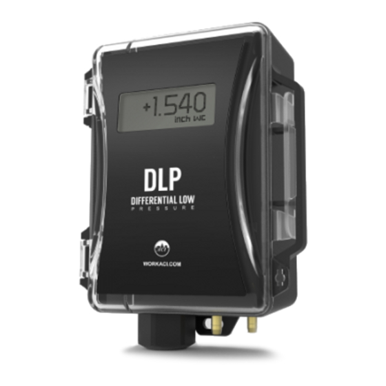
The DLP Series is based on a piezoresistive, silicon
sensing element which senses Di erential Pressure
and provides an analog output. Field selectable
analog outputs include 0-5 and 0-10 VDC, or 4-20
mA which correlate to a uni or bi-directional
pressure range from 0-0.1" up to 0-40" of water
column, depending on your model selection. Each
unit has up to 8 eld selectable, uni or bi-directional
ranges (see Figure 6 p. 3).
MEDIA
The DLP can be used to monitor the di erential
pressure in any application that uses dry air or inert
gas.
Mounting
Find a suitable location for the enclosure. The DLP
has 2 two mounting holes located on the top and
bottom anges. Drill pilot holes for the (2) #8 x 3/4"
self-drilling screws(supplied). Use the enclosure ange as a guide, or use the dimensions listed in Figure 1.
Mount the unit vertically with the brass ttings pointing towards the ground. This ensures that any
condensation that may form in the tubing does not have an e ect on the pressure sensor. If mounting the
unit horizontally, a slight zero shift may occur and care must be taken to prevent moisture from building
up in the sensor.
FIGURE 2: DIN RAIL MOUNTING
Automation Components, Inc.
2305 Pleasant View Road | Middleton, WI 53562
Phone: 1-888-967-5224 | Website: workaci.com
FIGURE 1: DLP DIMENSIONS
4.35"
(110.43 mm)
CORDGRIP /
1/2 " CONDUIT FITTING
DIN RAIL
Page 1
Phone: 1-888-967-5224
Website: workaci.com
2.48"
(62.99 mm)
2.23"
(56.52 mm)
5.56"
(141.29 mm)
6.02"
(152.82 mm)
HIGH PRESSURE PORT
-H
-L
LOW PRESSURE PORT
DIN RAIL
DIN RAIL
CLIP
Version: 15.0
Version: 15.0
I0000777
I0000777
Advertisement

Related Manuals for aci DLP Series


Summary of Contents for aci DLP Series
- Page 1 (110.43 mm) (56.52 mm) correct positions and then power on the transmitter. GENERAL INFORMATION The DLP Series is based on a piezoresistive, silicon sensing element which senses Di erential Pressure 5.56" and provides an analog output. Field selectable (141.29 mm) analog outputs include 0-5 and 0-10 VDC, or 4-20 6.02"...
-
Page 2: Din Rail Mounting (Optional)
FIGURE 3: PITOT TUBE INSTALLATION DIN RAIL MOUNTING (Optional) Attach the DIN Rail Mounting accessory to the back of the enclosure using the two screws provided. To mount the sensor on the DIN Rail, place the bottom of the DIN Rail Clip into the 35mm DIN Rail and push the unit upward to engage the spring clip. -
Page 3: Digital Controller
• If the 24 VDC or 24VAC power is shared with devices that have coils such as relays, solenoids, or other inductors, each coil must have an MOV, DC/AC Transorb, Transient Voltage Suppressor (ACI Part: 142583), or diode placed across the coil or inductor. The cathode, or banded side of the DC Transorb or diode, connects to the positive side of the power supply. -
Page 4: Zero Function
Open the cover of the enclosure. ACI recommends 16 to 26 AWG twisted pair wires or shielded cable for all transmitters. Twisted pair may be used for 2-wire current output transmitters or 3-wire for voltage output. Connect the wires to the unit’s nger push-button terminal blocks. Each DLP unit can be con gured to three output signals: 4-20 mA, 0-5 V or 0-10 V. - Page 5 TABLE 3: MAXIMUM PRESSURE UNIDIRECTIONAL AND BIDIRECTIONAL MODE ACI Part # Maximum Pressure (inWC) The DLP can operate in either unidirectional mode (0 – X inWC) or bidirectional mode (± X inWC). Each unit could have DLP-001-W up to eight eld selectable, uni or bidirectional ranges.
-
Page 6: Unidirectional Mode
DLP utilizes a digital pot for Span calibration and is factory set. There is no Span potentiometer for adjustment. In the event you require Span calibration, the unit must be sent back to ACI. The O set can be adjusted using the Auto Zero function discussed on pg 4. Drift is a function of stress relaxation over time and this results in the o set shifting, and not the span . -
Page 7: Product Specifications
Do not dispose of with household waste. Do not burn. WARRANTY The ACI DLP is covered by ACI’s Five (5) Year Limited Warranty, which is located in the front of ACI’S SENSORS & TRANSMITTERS CATALOG or can be found on ACI’s website: www.workaci.com.