Table of Contents
Advertisement
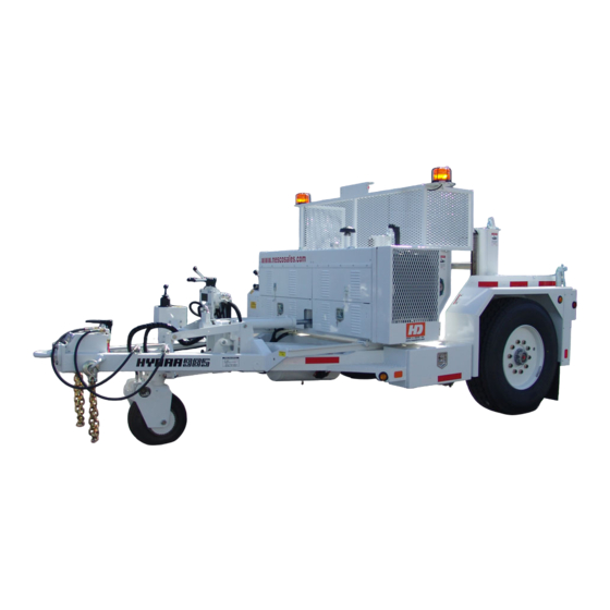
HYDRA 985
The information, specifications, and illustrations in this manual are on the basis of
information available at the time it was written. The specifications, torque values,
pressures of operation, measurements, adjustments, illustrations, and other
items can change at any time. These changes can affect the service of the given
product.
For the complete and most current information, contact:
Hogg & Davis, Inc
P.O. Box 405 / 3800 Eagle Loop
Odell, OR 97044-0405
541-354-1001
541-354-1080 Fax
For most recent manual
version please visit:
www.hoggdavis.com
Advertisement
Table of Contents

Related Manuals for HOGG & DAVIS HYDRA 985

Summary of Contents for HOGG & DAVIS HYDRA 985
- Page 1 HYDRA 985 The information, specifications, and illustrations in this manual are on the basis of information available at the time it was written. The specifications, torque values, pressures of operation, measurements, adjustments, illustrations, and other items can change at any time. These changes can affect the service of the given product.
-
Page 2: Table Of Contents
HYDRA 985 Contents PRODUCT WARNINGS ........4 OPERATIONS ............5 DIESEL ENGINE SPECIFICATIONS ....................... 6 INTRODUCTION ............................6 GENERAL SPECIFICATIONS........................6 TRAILER ORIENTATION ..........................8 MAIN FRAME AND AXLE ........................... 8 CONTROLS ..............................9 LOADING INSTRUCTIONS ........................10 HYDRAULIC CONTROLS ........................... 11 Power Unit Features ........................... - Page 3 HYDRA 985 UNDERGROUND PULLING ........................23 SERVICE ............24 HYDRA 985 Lubrication ........................25 JACKSTAND INSTALLATION ......................... 26 DRIVE ROLLER MAINTENANCE ......................27 DRAWDAR INSPECTION ........................28 ACME ADJUSTING SCREW ........................28 MANDREL RACK STABILIZER INSTALLATION ..................29 © COPYRIGHT 2016 HOGG & DAVIS, INC...
-
Page 4: Product Warnings
HYDRA 985 PRODUCT WARNINGS These warning labels and others like it are placed in critical areas of the machine. The warnings are to be read and fully understood prior to operation of the unit. © COPYRIGHT 2016 HOGG & DAVIS, INC... -
Page 5: Operations
HYDRA 985 OPERATIONS © COPYRIGHT 2016 HOGG & DAVIS, INC... -
Page 6: Diesel Engine Specifications
HYDRA 985 INTRODUCTION DIESEL ENGINE SPECIFICATIONS The Hogg & Davis, Inc HYDRA 985 Cable Reel Unit 3TNV88-BDSA General is an advanced design cable pulling trailer that Specification 36.0 HP (26.9 kW) @ 3000 rated rpm* provides tremendous pulling forces in a compact ____________________________________________________________________________ vehicle. - Page 7 HYDRA 985 © COPYRIGHT 2016 HOGG & DAVIS, INC...
-
Page 8: Trailer Orientation
MAIN FRAME AND AXLE TRAILER ORIENTATION The main frame and axle carry the entire weight of the The HYDRA 985 is made up of four (4) major trailer and its payload. Constructed of heavy steel, the working components (see Fig.1) they are: main frame will provide many years of durable service and minimum maintenance. -
Page 9: Controls
The control panel has a variety of gauges and switches that control certain functions during the operation of the HYDRA 985. Here is a description of these controls. (Figure 2) A. Hydrastatic Pressure Gauge: This gauge alerts the operator to the system pressure at all times during operation. -
Page 10: Loading Instructions
HYDRA 985 LOADING INSTRUCTIONS © COPYRIGHT 2016 HOGG & DAVIS, INC... -
Page 11: Hydraulic Controls
HYDRA 985 HYDRAULIC CONTROLS Power Unit Features A- ACME ADJUSTING SCRW B - EXTENDED SHAFT GUARD COVER C- POWER UNTI DRIVE SHAFT 2 7/16" © COPYRIGHT 2016 HOGG & DAVIS, INC... -
Page 12: Front Hydraulic Controls
HYDRA 985 FRONT HYDRAULIC CONTROLS A - STEER GO SYSTEM B - FRONT HYDRAULIC CONTROLS (DRAWBAR, POWER UNIT, LEFT AND RIGHT MANDREL RACKS © COPYRIGHT 2016 HOGG & DAVIS, INC... -
Page 13: Front Control Bank
HYDRA 985 FRONT CONTROL BANK A - DRAWBAR RAISE AND LOWER B - POWER UNIT FORWARD AND BACK C,D - RIGHT AND LEFT AND RIGHT MANDREL RACK RAISE AND LOWER © COPYRIGHT 2016 HOGG & DAVIS, INC... -
Page 14: Reel Carrying Racks (Mandrel Racks)
HYDRA 985 POWER UNIT The Power Unit consists of the engine, Hydrostatic Transmission Drive Unit, Drive Rollers, Engine Controls, hydraulic reservoir and auxiliary power shaft. The power unit supplies power for all hydraulic functions and turns the reels to provide cable pulling. Pulling controls are located at the power unit, the rear curb side of the trailer. -
Page 15: Jackstands
HYDRA 985 JACKSTANDS JACKSTANDS ARE STABILIZING LEGS LOCATED AT THE REAR OF THE TRAILER. THE JACKSTANDS SHOULD BE USED DURING ALL PULLING OPERATIONS In Fig 5, the jack stand at the left is shown in the stowed or carried position. The jack stand at the right is shown in the down or pulling position. -
Page 16: Steer-Go Operation
MANUERVERING INSTRUCTIONS One of the main features of the HYDRA 985 is its ability to maneuver under its own power by use of the Powered Idler Wheel and the Steer Go System. -
Page 17: To Steer And Move
HYDRA 985 THE JOYSTICK The joystick is a two-axis control that controls both steering and motion of the idler wheel functions. The joystick is either mechanically linked or electronically controlled (depending on options) to hydraulic control valves. Mechanical valves are spring return to neutral. Electronic joysticks are also spring return to neutral. -
Page 18: On Board Air Compressor
HYDRA 985 BRAKE CONTROLLERS Brake controllers on the HYDRA 985 are what is commonly used in an air brake trailer. Figure 6 shows us the location of the following: C: The hand control located on the apex of the trailer... -
Page 19: Tool Circuit (Optional)
HYDRA 985 TOOL CIRCUIT (OPTIONAL) Some trailers may be equipped with an optional hydraulic tool circuit. The circuit is designed for tools which are used intermittently or for short duration such as a pump or hydraulic cutters. It is NOT designed for uses of long or continuous duration such as hydraulic blowers or generators. -
Page 20: Levelwind Operations
HYDRA 985 LEVELWIND OPERATIONS Some units are equipped with a Level wind System. This system is hydraulically actuated boom style level wind located at the rear of the trailer (Fig. 9) There are two switch locations to operate the level wind. They are at the main control panel and the rear control panel located at the curbside fender. -
Page 21: Levelwind Components
HYDRA 985 LEVELWIND COMPONENTS The following are the main components in the LW Assembly A. Hinge Pin B. Lower Boom Assembly C. Level wind cylinder D. Turnbuckle E. Hydraulic QD fittings F. Carriage Assembly G. Upper Boom Assembly H. Lock pin for Boom Assemblies... -
Page 22: Pulling Procedures
HYDRA 985 PULLING PROCEDURES Although all jobs will vary, below is a basic description of how to operate the HYDRA 985. Please consult your Employers rules and regulations and always consult and follow guidelines set for by the IEEE. OVERHEAD WIRE The following is a basic description of how to set up and pull overhead wire. -
Page 23: Underground Pulling
HYDRA 985 UNDERGROUND PULLING 1. Position the trailer over the manhole (vault opening, etc). The best position for maximum pulling power is to position the reel DIRECTLY over the pull. 2. Lower trailer drawbar 3. Set Jack stands 4. Raise trailer drawbar to set pressure on the jack stands. It is not advised to remove the tires from the ground when setting the jack stands. -
Page 24: Service
HYDRA 985 SERVICE © COPYRIGHT 2016 HOGG & DAVIS, INC... -
Page 25: Hydra 985 Lubrication
HYDRA 985 HYDRA 985 Lubrication The following lubrication instructions are offered as "rule of thumb". Precise lubrication instructions will vary with each usage of each unit. CHECK ALL LUBRICATIONS BEFORE EACH USE ENGINE: Consult Engine Manual for precise instructions. Unit is delivered by Hogg & Davis, Inc. with 10W40 oil. -
Page 26: Jackstand Installation
HYDRA 985 JACKSTAND INSTALLATION When installing any model Hogg and Davis Jack stand, the following procedure should be Used. 1. Determine If stand Is left or right. Hole in side of stand should line up with holding lug on trailer when teeth of stand engage with spring loaded ratchet pawl. -
Page 27: Drive Roller Maintenance
HYDRA 985 DRIVE ROLLER MAINTENANCE The "heart" of any friction drive cable pulling machine is the rollers that transfers the power to the reel. This Is also usually the highest mortality Item on these units because they take the full brunt of all the pulling torque. -
Page 28: Drawdar Inspection
HYDRA 985 ACME ADJUSTING SCREW Ninety to ninety-five percent of all damage to the acme adjusting screws on the above machine Is in the form of bending. Since it is nearly impossible to straighten them to work properly, it is necessary to replace them. -
Page 29: Mandrel Rack Stabilizer Installation
HYDRA 985 MANDREL RACK STABILIZER INSTALLATION The mandrel rack stabilizers are very critical to the proper operation of your trailer. One stabilizer Is attached to each mandrel rack. This stabilizer keeps the racks rigid and takes all the strain put against the racks when pressure Is applied by the power unit against the reel. - Page 37 Common SPN.FMI Codes TEXT TRANSLATION % Accelerator Position #3 (Throttle 2) Voltage Above Normal or Shorted to High Source H Percent Accelerator Position #3 (Throttle 2) Voltage Below Normal or Shorted to Low Source Percent Accelerator Position #2 (Throttle 1) Voltage Above Normal or Shorted to High Source Percent Accelerator Position #2 (Throttle 1) Voltage Below Normal or Shorted to Low Source Accelerator Pedal Position (Multi-State Throttle) Voltage Above Normal, or Shorted to High Source Accelerator Pedal Position (Multi-State Throttle) Voltage Below Normal or Shorted to Low Source...
- Page 38 Common SPN.FMI Codes TEXT TRANSLATION Injector Wiring Shorted to battery Injector Wiring Shorted to ground Sensor Supply Voltage 1 (+5V DC) Voltage Above Normal or Shorted to High Source Sensor Supply Voltage 1 (+5V DC) Voltage Below Normal or Shorted to Low Source Power Supply Low voltage to injectors Power Supply Power interruption Reprogram Controller ECU problem...
- Page 39 Common SPN.FMI Codes TEXT TRANSLATION 1076 Fuel Injection Pump Fuel Control Value Error 1076 Fuel Injection Pump Fuel Control Value Error 1076 Fuel Injection Pump Fuel Control Valve Error 1076 Fuel Injection Pump Fuel Control Valve Error 1076 Fuel Injection Pump Fuel Control Valve Error 1076 Fuel Injection Pump Fuel Control Valve Error 1076...
- Page 40 Appendix D 2G-ECO Governor Controller DTC Table Ver. 3.8.1 2007/5/18 J1939 Lamp Status J1939 Format Description (DEC) (Hex) 4 Engine Fuel Rack Position Sensor : Shorted to low source 1210 3 Engine Fuel Rack Position Sensor : Shorted to high source (Engine (E-ECU drive) start) 4 Accelerator Pedal Position Sensor "A"...
- Page 41 HYDRA 985 Parts Manual The information, specifications, and illustrations in this manual are on the basis of information available at the time it was written. The specifications, torque values, pressures of operation, measurements, adjustments, illustrations, and other items can change at any time. These changes can affect the service of the given product.
- Page 42 HYDRA 985 TABLE OF CONTENTS Isometric View Unit Dimensions Power Unit with brake (Front view) Power Unit with brake (Rear view) Power Unit brake Brake Manifold Power Unit with brake drive assembly Power Unit without brake (Front view) Power Unit without brake (Rear view) 10.
- Page 43 HYDRA 985 34. HYLW3 Screw Levelwind 35. HYLW3 Screw Levelwind 36. Manual Jackstands 37. Hydraulic Outriggers 38. Hydraulic Outriggers Bill of Materials 39. Tank Assembly for Power Unit Without Brake 40. Tank Assembly for Power Unit With Brake 41. Hi-Vis Screen for power Unit Without Brake...
- Page 44 ITEM NO. PART NUMBER DESCRIPTION QTY. Hydra 985 Power Unit T4f See Power unit sheet HYEC7 7 wire electrical hood E04017 Eye, Pintle HYPS1 Power Steering, Drive Assembly HYPS2 Power Steering, Control Assembly D05150 Toolbox Door Page 1 Manual Jackstands...
- Page 45 2 " 84 29 " 16'-2" 194 5 " 8'-1" 97 3 " Page 2 HYDRA 985...
- Page 46 Lock, T-Handle D05202 RH PU/B Door D05203 LH PU/B Door C29200 Radiator Cover R19025 Battery hold down H10060 Tray, battery G09203 Guard, Chain Page 3 H10020 Registration Holder HYDRA 985 S29933 Sprocket Power Unit With Brake C32050 Cylinder, Power Unit...
- Page 47 Bracket, Acme Screw Adjust Long P06193 Pin, Roll 1/4 x 2-1/2 N04130 Nut 1 1/2-12 Z Tanks Tank Assembly S04153 Screw, Acme Long Page 4 M08010 Hydra Motor HYDRA 985 HYBAC Air Brake Compressor Option Power Unit With Brake H10020 Registration Holder...
- Page 48 Key, 1/2 x 1/2 x 2-1/2 S43012 Shaft B11368 Bolt Hx head 1/2-13x1-1/2 W01565 Washer, Split Lock 1/2" B07198 Bearing, SC Pilot Flange 2-7/16" C04024 Caliper, Fail Safe Page 5 B15112 Brake Mount HYDRA 985 S29004 Sprocket D100B16 POWER UNIT BRAKE P09200 Bearing Mount Plate...
- Page 49 QTY. ITEM NO. PART NUMBER DESCRIPTION M04001 Manifold, Brake V02066 Valve, 2Way Solenoid Cartridge V02069 Valve, 3Way Solenoid Cartridge S40001 PDI Switch F05706 Fitting, 4-4 FNPT-SAE F05018 -4 FNPT to -4 NPT 45° Page 6 G02035 0-5k psi bottom mount V02067 Valve, check Brake Manifold...
- Page 50 Key, 1/2 x 1/2 x 7-3/4 K01010 Key, 1/2 x 1/2 x 2-1/2 W01565 Washer, Split Lock 1/2" Page 7 B11366 Bolt Hx head 1/2-13x2 Hydra 985 Drive Assembly S29023 Sprocket, Drive (For Power Unit With Brake) B21055 Shaft Collar...
- Page 51 Hood, Power Unit D05205 RH PU Door D05204 LH PU Door C29200 Radiator Cover H10020 Registration Holder S29933 Sprocket H10060 Tray, battery Page 8 R19025 Battery hold down HYDRA 985 G09200 Guard, Chain Power Unit Without Brake C32050 Cylinder, Power Unit...
- Page 52 Pin, Roll 1/4 x 2-1/2 N04130 Nut 1 1/2-12 Z Tank Assembly See Tank Assy Sheet S04153 Screw, Acme Long M04043 Manifold Assembly Page 9 M08010 Hydra Motor HYDRA 985 HYBAC Air Brake Compressor Option Power Unit Without Brake H10020 Registration Holder...
- Page 53 Cover, Driveshaft Capstan C29009 Cover, Side Control Panel 985 Front Controls T4 See Controls Sheet L08025 Lock, T-Handle D05208 Door, Curbside C32050 Cylinder, PowerUnit Page 10 D05209 Door, Streetside HYDRA 985 H05007 Hood, Powerunit Power Unit Tier 4 S08043 Screen, Operator Safety...
- Page 54 Bracket, Acme Screw Adjust P06193 Pin, Roll 1/4" x 2-1/2" N04130 Nut, Hx 1-1/2"-12 Z See Tanks Sheet 985 Std Tanks T4f Page 11 Manifold M04043 Motor, Hydraulic HYDRA 985 M08010 Power Unit Tier 4 HYBAC Air Brake Compressor Option...
- Page 55 Bolt Hx head 1/2-13x2 S43125 Shaft, Drive K01020 Key, 1/2 x 1/2 x 7-3/4 B07275 Bearing, 2-7/16 Pillow Block Page 12 K01010 Key, 1/2 x 1/2 x 2-1/2 Hydra 985 Drive Assembly S29023 Sprocket, Drive (For Power Unit Without Brake) B21055 Shaft Collar...
- Page 56 Nut Hex Jam 5/8-11 B15968 Bracket, Drive Roller Adjusting A07055 Rod, Chrome 1" W01294 Washer Flat SAE 1 N04095 Nut Hex Jam 1-14 Page 13 N04098 Nut, Acme Screw HYDRA 985 POWER HEAD S04560 Screw FHSHCS 1/2-13x2 H08045 Roller Housing...
- Page 57 (IMPROVED TRACTION FOR WET URETHANE ROLLER CONDITIONS) ITEM NO. PART NUMBER DESCRIPTION QTY. B07135 Bearing, 1" I.D. S24010 Spacer, Drive Roller Page 14 R18024 Roller, Drive Urethane R18025 Roller, Drive Rubber HYDRA 985 DRIVE ROLLS C27005 Core, Drive Roller Standard...
- Page 58 2"ID x 9" long H07712-9-2 2"ID x 9" long Y01055 Yoke, 1/4" clevis C34010 Controller, Electronic Throttle 1 M09003 Mount, Throttle C28026 Pump Coupler/ Flywheel Page 15 P09097 Pump Adapter Plate P20070 Pump, Hydraulic HYDRA 985 ENGINE ASSEMBLY P20103 Pump, 10gpm...
- Page 59 ITEM NO. PART NUMBER DESCRIPTION QTY. C35010 Cooler, Oil M09041 Mount engine front Engine E02033 I04003 Insulator, Small M09042 Mount engine rear C28026 Pump Coupler/ Flywheel P09097 Pump Adapter Plate Page 16 P20070 Pump, Hydraulic P20103 Pump, 10gpm Engine Assembly Tier 4 B15171 Bracket, Radiator 985 T4f...
- Page 60 ITEM NO. PART NUMBER DESCRIPTION QTY. S41100 Switch Ignition JDD S04601 10-32 X 3/4" PAN HEAD C34030 Controller, Joystick MCH S41001 JD Pre-Heat Timer S40150 Switch, DP/DT Momentary L04025 Light, Pilot S40008 Switch, SP/DT Maintained S40153 Switch, SP/DT Maintained w/center Page 17 P03020 Control Panel...
- Page 61 ITEM NO. PART NUMBER DESCRIPTION QTY. S41100 Switch Ignition JDD C34030 Controller, Joystick MCH S41001 JD Pre-Heat Timer P03020 Control Panel S40150 Switch, DP/DT Momentary L04025 Light, Pilot S40008 Switch, SP/DT Maintained S40153 Switch, SP/DT Maintained w/center Page 18 S40035 Switch, SP/ST Toggle G02033 Gauge, Livorsi 4 in 1...
- Page 62 ITEM NO. PART NUMBER DESCRIPTION QTY. P03023 Panel, Control C34030 Controller, Joystick MCH G02005 Gauge, Fuel Level S40100 Switch, SP/DT Momentary S40035 Switch, SP/ST Toggle Page 19 K02707 Display, Yanmar T4 w/ Keyswitch S40070 Switch, Key Cole Hersee Controls Tier 4 D30150 Decal, Control Panel T4f...
- Page 63 ITEM NO. PART NUMBER DESCRIPTION QTY. C34030 Controller, Joystick MCH B13960 Rear Control Panel Page 20 S40150 Switch, DP/DT Momentary S40035 Switch, SP/ST Toggle REAR CONTROLS S40100 Switch, SP/DT Momentary...
- Page 64 Rebuild kits for Rotary Actuator (Item 8) K02113- Seal kit K02114- Bearing kit C10075- Drive Chain Page 21 HYDRA 985 STEER-GO SHEET 1 of 2...
- Page 65 Axle, Drive Wheel N04040 Nut, Lug 1/2"-20 Z W03907A Wheel and Tire assy 18x7 M08050 Motor, Hydraulic Drive S29005 Sprocket, Drive B11343 Bolt, Hx Head 3/8"-16 x 1-1/4" S29905A Sprocket and Hub Assembly Page 22 HYDRA 985 STEER-GO SHEET 2 of 2...
- Page 66 Fitting, 8-8 STR STC F05754 Fitting, 4-6 Str SAE L03055 Lever, Steer-Go Joystick K02500 Kit, Linkage V02401 Valve, Priority Flow V02185 Vavle, Check Page 23 M04015 Manifold Steer-Go HYDRA 985 V02186 Valve, Relief V02021 Valve, Directional STEER-GO CONTROLS C29120 Cover, Steer-Go...
- Page 67 ITEM NO. PART NUMBER DESCRIPTION QTY. V02012 Valve, pop-off 140psi F05778 1/4 NPT to 3/8 Air Line F05150 Fitting, Street Elbow 4-4 S40120 Extreme Air pressure switch F05059 Fitting, Pipe Cross 4-4-S V02220 Valve, check one way C21020-CB 50amp Circuit Breaker Page 24 B15037 Bracket, Compressor...
- Page 68 LOCATED ON TONGUE OF TRAILER Page 25 HYDRA 985 AIR BRAKE ASSEMBLY...
- Page 69 S15030 Shoe, Air Brake 16-1/2x5 N04201 Nut, Hub Inner W01202 Washer, Locking Air Brake W01201 Washer, Lock Spindle Tab N04202 Nut, Hub Outer S05130 Seal, Grease Hub B07140 Bearing, Inner B07085 Bearing, Outter Page 26 HYDRA 985 AIR BRAKE ASSEMBLY...
- Page 70 ITEM NO. PART NUMBER DESCRIPTION QTY. C32040 Mandrel Cylinder LH D3188 C32025 Mandrel Cylinder RH D3189 R01925 Rack, Mandrel LH R01945 Rack, Mandrel RH L08015A Lock Assy, Mandrel Rack LH H02045A Handle, Mandrel Lock LH B07365 Bearing, I-Glide 3/4x1x5/8 S30021 Stabilizer, Outside S30005 Stabilizer, Inner...
- Page 71 Page 28 HYDRA 985 LEVELWIND HYLW...
- Page 72 Bracket, Swing-away Fairlead P06193 Pin, Roll 1/4 x 2-1/2 P09170 Plate, Sub V02145 Valve Capstan/Levelwind V02075 Valve, Loadlock F05755 Fitting, 6-6 Str SAE S04475 Screw, Set Sq Head 1/2 x 1 C17015 Clip, Hitch Pin 5" Page 29 HYDRA 985 LEVELWIND HYLW...
- Page 73 10 11 14 16 15 Page 30 HYDRA 985 LEVELWIND HYLW2...
- Page 74 Guard, HYLW2 N04545 Nut Hex Nylock 3/8-16 T15905A Turnbuckle Assembly P06095 Pin, 1/2 x 2 W01005 Washer Flat SAE 1/2 P06933 Pin, Cotter 1/8x1 Z P06830 Pin Lower Pivot P09170 Plate, Sub V02145 Valve Capstan/Levelwind Page 31 HYDRA 985 LEVELWIND HYLW2...
- Page 75 Page 32 Screw Levelwind HYLW3...
- Page 76 ITEM NO. PART NUMBER DESCRIPTION QTY. F09061 Frame Screw Levelwind P09079 Plate Motor Mounting B11382 Bolt, Hx Head 3/4"-16 x 1-3/4" W01585 Washer, Split Lock 3/4"zinc B07130 Bearing B11364 Bolt, Hx Head 1/2"-13 x 1-3/4" N04555 Nut, Hx Nylock® 1/2"-13 P09081 Plate Swivel End P06043...
- Page 77 Page 34...
- Page 78 #40~#42 guard bolts Page 35 Screw Levelwind HYLW3...
- Page 79 Complete Assembly Part Number: J01015A QTY. ITEM NO. PART NUMBER DESCRIPTION S17930 Sleeve, Jackstand bolt on LH J01010 Jackstand, 985/6500 P01020 P04005 Pawl S28075 Spring, Jackstand / EPO P06100 3/4" X 2-1/2" PIN H02015 Handle, Jackstand P06105 1/2" X 2-1/2" PIN S37010 5/8"-11 STUD B11060...
- Page 80 Complete Assembly Part Number: J01016A QTY. ITEM NO. PART NUMBER DESCRIPTION B11060 Bolt, Hx Head 7/8"-9 x 3" Z8 P01020 S37010 5/8"-11 STUD J01010 Jackstand, 985/6500 P06105 1/2" X 2-1/2" PIN W01005 Washer, Flat SAE 1/2"zinc P06933 Pin, Cotter 1/8" x "1 Z H02015 Handle, Jackstand W01585...
- Page 81 Page 37 Hydraulic Outriggers #11 & #12 are for Units with a Levelwind, Otherwise use (2) #10's...
- Page 82 ITEM PART NUMBER DESCRIPTION QTY. J04005 Jack, Hydraulic Outriggers C32015 Cylinder Outrigger F05565 Fitting, 6-4 Elbow P06200 Pin, Outrigger Cylinder Upper C20040 Spacer, Outrigger Cylinder P06165 Pin, Lower Outrigger S04261 Screw, Set 1/2-13x1/2 CP P01035 Pad, Hydraulic Outrigger C29013 Cover, Outrigger Top C29055 Cover, Outrigger Hoses C29058...
- Page 83 Sender, Fuel Level N02005 1-1/4" Closed Nipple V02001 Valve, Ball 1-1/4" NPT 1 F04021 Filter Head F04020 Filter 10 micron G02010 Gauge, Suction N07001 Nozzle, Fuel Fill C06205 Cap, Fuel Page 39 Hydra 985 Tank assembly (For Power Unit Without Brake)
- Page 84 ITEM NO. PART NUMBER DESCRIPTION QTY. T01952 Tank, Fuel S46015 Sender, Fuel Level F04020 Filter 10 micron G02010 Gauge, Suction F04021 Filter Head N02005 1-1/4" Closed Nipple V02001 Valve, Ball 1-1/4" NPT T01953 Tank, Hydraulic N07002 Neck, Hydraulic fill C06155A Cap, Hydraulic Page 40 C06205...
- Page 85 ITEM NO. PART NUMBER DESCRIPTION QTY. G09019 Guard, strobe Page 41 Light Strobe L04105 Hydra 985 HI-VIS Screen S08040 Screen (For Power Unit Without Brake) L04060 Light Bar, 3 light...
- Page 86 Washer, Flat SAE 3/8"zinc W01545 Washer, Split Lock 3/8"zinc N04108 Nut, Hx 3/8"-16 H10002 Holder, Fuse F01002 Fuse, 30amp Page 42 S40035 Switch, SP/ST Toggle Hydra 985 HI-VIS Screen N04203 Nut Hex 10-32 (For Power Unit With Brake) L04060 Light Bar, 3 light...
- Page 87 Valve Capstan/Levelwind P09170 Plate, Sub F05762 Fitting, 6-10 Str SAE M08050 Motor, Hydraulic Drive G09021 Guard, Toggle Switch S40153 Switch, SP/DT Maintained w/center Page 43 F05170 Fitting, -6 JIC bulkhead B15998 Bracket, Capstan Mount HYDRA 985 HYDRAULIC CAPSTAN C38905A Cathead, Capstan...
- Page 88 ITEM PART NUMBER DESCRIPTION QTY. H05070 Hood, Electrical 7 wire Page 44 S21035 Socket 7-wire Pollak P10025 Plug, 7-Wire w/Spring HYDRA 985 ELECTRICAL CONNECTION C02038-1 cable hydra...
- Page 89 L04035 Light, 2" Amber C26165 Liquidtite 90 L04047 Light, ABS 2" Amber B22050 Block, 4 Pole Terminal Strip Page 45 P10175 Plug, Plastic Button 1-1/4" HYDRA 985 G08010 Grommet, 4" Tail/Stop/Turn Standard Fender Lights L04030 Light, 4" Tail Stop Turn...
- Page 90 G08005 Liquidtite 90 C26165 L04036 Light, 2" Amber LED L04037 Light, 2" Red LED B13048 Box, light Vertical Page 46 L04080 Light, License HYDRA 985 Grommet, 4" Tail/Stop/Turn G08010 LED Standard Fender Lights L04305 Light, 4" Tail Stop Turn LED...
- Page 91 BOM Table ITEM NO. PART NUMBER DESCRIPTION QTY. V02138 Inlet w/o Relief V02130 Double Acting V02135 Single Acting V02065 Outlet w/PB B15910A Handle, Straight B15912A 90° lever assembly Page 47 F05150 Fitting, Street Elbow 4-4 V02120 G02055 3K bottom mount Valve Bank 4 Section V02150 relief valve...
- Page 92 Hogg & Davis Vehicle Specification – Model # Hydra 985 Latest Model, all new, single axle, cable pulling unit. Trailer General: to be engineered for safe, rapid, one-person operation. Trailer must accommodate both underground and overhead power systems. 21,980 lbs...
- Page 93 Capable of 24,000 lbs line pull at a 19 inch core diameter Reel Drive: and 80 inch flange diameter reel. The drum drive is accomplished by 4 powered drive rollers that contact the cable reel flanges with 14,000 lbs of force. These rollers are adjustable for variable reel widths with a manually cranked screw.
- Page 94 Trailer to have stop, tail, turn and marker lights. Wiring to be Lighting: per ICC specifications. At trailer tongue, install a 7-wire socket with 36” whip. All wiring to be enclosed in hard conduit in the trailer frame. All lights to be double shock mounted Lexan lens with pigtails (FMVSS108).
- Page 95 Page 43 Page 51...
- Page 96 Page 52...
- Page 97 Page 53...
- Page 98 Page 54...
- Page 99 Page 55...
- Page 100 Page 56...
- Page 101 Page 57...
- Page 102 Page 58...
- Page 103 Page 59...
- Page 104 Page 60...
- Page 105 Page 61...
- Page 106 Page 62...
- Page 108 Page 64...
- Page 109 Page 65...
- Page 110 Tier 4 D30009 D30027 D30010 D30015 D30032 D30023 D30001 D30018 D30034 D30038 D30028 D30026 D30036 D30021 D30022 D30069 R09044 D30042 R09043 D30037 Page 66 HYDRA 985 Decals...
- Page 111 D30020 D30003 D30024 D30019 D30002 Tier 4 D30025 D30151 D30030 Tier 4 D30029 D30128 D30111 D01013 D30150 D30039 Page 67 HYDRA 985 Decals...
- Page 112 ITEM NO. PART NUMBER DESCRIPTION QTY. D30038 Decal, Hydra 985 Tongue D30037 Decal, Important - Idler Wheel D01013 Decal, 4 Bank Valve D30001 HD Logo 6x9 D30128 Established 1947 D30018 Decal, HD 1/2" x 9" D30025 Decal, Steer-Go Directions D30034...
- Page 113 ITEM NO. PART NUMBER DESCRIPTION QTY. D30028 Decal, Danger Twisty Man D30022 Decal, Danger Fluid Pressure D30021 Decal, Untrained Operator D30032 Decal, Check Oil Daily D30036 Decal, Electrocution Hazard D30019 Decal, HD 3/4"x9" Red D30003 Decal, Hydra Hog 10"x7" D30023 Decal, Caution Extended Shaft Page 69 D30151...
- Page 114 ITEM NO. PART NUMBER DESCRIPTION QTY. D30038 Decal, Hydra 985 Tongue D30034 Decal, Grounding Lug R09044 Reflector, Amber 2x3-1/2 T19001 Red/White Reflective tape D30015 Decal, Hot Surface D30036 Decal, Electrocution Hazard D30028 Decal, Danger Twisty Man Page 70 D30042 Decal, Keep Hands Clear...
Need help?
Do you have a question about the HYDRA 985 and is the answer not in the manual?
Questions and answers