Table of Contents
Advertisement
Quick Links
Advertisement
Table of Contents

Related Manuals for Agilent Technologies E7490A


Summary of Contents for Agilent Technologies E7490A
- Page 1 Artisan Technology Group is your source for quality new and certified-used/pre-owned equipment SERVICE CENTER REPAIRS WE BUY USED EQUIPMENT • FAST SHIPPING AND DELIVERY Experienced engineers and technicians on staff Sell your excess, underutilized, and idle used equipment at our full-service, in-house repair center We also offer credit for buy-backs and trade-ins •...
- Page 2 Agilent Technologies E7473A, E7474A, E7475A, E7490A Wireless Solutions Getting Started Guide Agilent Technologies Artisan Technology Group - Quality Instrumentation ... Guaranteed | (888) 88-SOURCE | www.artisantg.com...
- Page 3 HP businesses: test and measurement, semiconductor products, healthcare solutions and chemical analysis. We at Agilent Technologies are working diligently to make this transition as seamless as possible for you, however, we are not able to make all changes immediately.
- Page 4 Artisan Technology Group - Quality Instrumentation ... Guaranteed | (888) 88-SOURCE | www.artisantg.com...
- Page 5 Getting Started Guide Agilent Technologies E7473A, E7474A, E7475A, E7490A Wireless Solutions Artisan Technology Group - Quality Instrumentation ... Guaranteed | (888) 88-SOURCE | www.artisantg.com...
- Page 6 Notice Warranty Agilent Technologies, Inc. Agilent Technologies, Inc. specifically disclaims the The information contained in This Agilent Technologies, Inc. Company 1997-2000 implied warranties of this document is subject to instrument product is warranted merchantability and fitness for a change without notice.
-
Page 7: Safety And Regulatory Information
Safety and Regulatory Information Safety and Regulatory Information Review this product and related documentation to familiarize yourself with safety markings and instructions before you operate the system. This product has been designed and tested in accordance with appropriate international standards. For more details on Safety and Regulatory Information, refer to Chapter 7, “Safety and Regulatory Information”... - Page 8 Safety and Regulatory Information iv Wireless Solutions Getting Started Guide Artisan Technology Group - Quality Instrumentation ... Guaranteed | (888) 88-SOURCE | www.artisantg.com...
-
Page 9: Welcome To Your Agilent Wireless Solutions
Welcome to Your Agilent Wireless Solutions Welcome to Your Agilent Wireless Solutions Thank you for choosing Agilent Technologies, Inc.. In this getting started guide, you’ll find the setup instructions you need to begin taking measurements. Follow These Steps To Do This... - Page 10 TDMA Cellular and PCS Network Test System Agilent E7475A GSM900, DCS1800 and GSM1900 Network Test Systems Agilent E7490A CDMA Base Station Over Air Maintenance Test System Portable Document Format - online version that can be viewed using Adobe ® Acrobat reader.
-
Page 11: Table Of Contents
Follow These Steps ........Agilent Technologies License Manager ...... - Page 12 Chapter : Trimble Placer GPS/DR ........2-54 Trimble Placer GPS 400 or SVeeSix .
- Page 13 Chapter : Preparing the Hardware ........Preparing the Software .
- Page 14 Software Measurement Specifications ..... . . 6-14 Agilent E7490A and Agilent E7473A CDMA System Specifications . . 6-25 Software Measurement Specifications ..... . .
-
Page 15: Installing The Software
Installing the Software Artisan Technology Group - Quality Instrumentation ... Guaranteed | (888) 88-SOURCE | www.artisantg.com... -
Page 16: What You'll Find In This Chapter
To Do This See This Install the system software “Installing the Software” on page 1-3 Install the License Manager software “Agilent Technologies License Manager” on page 1-5 Install Adobe Reader “Installing Adobe Reader” on page 1-6 Install Socket I/O card software “Installing Socket PCMCIA I/O Card Software”... -
Page 17: Installing The Software
4 Select the type of installation you want: The Destination Folder box appears. typical, compact, or custom, and click Next. •Typical: Includes Agilent E74xx application, Agilent Technologies recommends using the online help files, tutorial and documentation. Typical installation. Refer to page 6-68 to see if •Compact: Includes Agilent E74xx application... - Page 18 The list of folders found on your system is The default folder is “C:\Program Files\Agilent displayed. Technologies\ E74xx” or you can select a Agilent Technologies recommends using the different folder that can be found on your default folder system. Click Next.
-
Page 19: Agilent Technologies License Manager
Chapter 1: Installing the Software Agilent Technologies License Manager Agilent Technologies License Manager The hardware key that came with your Agilent Technologies system enables and secures the functionality you purchased from Agilent. The Agilent License Manager, automatically installed when you install the Agilent Wireless Solutions Software, enables you to manage licensing security information. -
Page 20: Installing Adobe Reader
Chapter 1: Installing the Software Installing Adobe Reader Installing Adobe Reader NOTE Before starting the installation process, ensure that you have removed previous versions of Adobe reader. This version is Adobe Reader 4.05. Do This See This 1 Insert the CD-ROM into the CD-ROM A Welcome dialog box appears detailing copyright drive, choose Start>Run, and type information. -
Page 21: Installing Socket Pcmcia I/O Card Software
I/O Card ™ User’s Guide for instructions on installing the software for that specific card. If you are using the USB 4-Port adapter, Agilent 86154A option 036, refer to the Agilent Technologies Indoor Test System Setup Guide for more information. Wireless Solutions Getting Started Guide 1- 7... - Page 22 Chapter 1: Installing the Software Installing Socket PCMCIA I/O Card Software 1-8 Wireless Solutions Getting Started Guide Artisan Technology Group - Quality Instrumentation ... Guaranteed | (888) 88-SOURCE | www.artisantg.com...
-
Page 23: Setting Up Your System
Setting Up Your System Artisan Technology Group - Quality Instrumentation ... Guaranteed | (888) 88-SOURCE | www.artisantg.com... -
Page 24: What You'll Find In This Chapter
Chapter 2: Setting Up Your System What You’ll Find in This Chapter What You’ll Find in This Chapter To Do This See This Connect the hardware “Hardware Installation Tips” on page 2-3 covers important setup information. “Connecting the Hardware” on page 2-7 covers setup of all types of systems. -
Page 25: Hardware Installation Tips
Chapter 2: Setting Up Your System Hardware Installation Tips Hardware Installation Tips Item Information Hardware security key The hardware security key must be connected to the parallel port of the PC. The application runs with a limited feature set without the key. - Page 26 Chapter 2: Setting Up Your System Hardware Installation Tips Item Information Configuring hardware The Wireless Solutions system assigns the serial port of the receiver to COM1 by default. If you want to use a different port, modify the serial port setting for the receiver in the application software as follows.
-
Page 27: Automatic Configuration
Chapter 2: Setting Up Your System Automatic Configuration Automatic Configuration The Agilent Wireless Solutions Software can automatically configure hardware that has been connected to your laptop. By clicking the Auto Config button, you begin the automatic configuration wizard (see Figure 2-1). - Page 28 Chapter 2: Setting Up Your System Automatic Configuration Figure 2-2 Enabling the auto-configuration customization features Figure 2-3 Defining COM ports and device types to be searched during the configuration process 2-6 Wireless Solutions Getting Started Guide Artisan Technology Group - Quality Instrumentation ... Guaranteed | (888) 88-SOURCE | www.artisantg.com...
-
Page 29: Connecting The Hardware
2-14 page 2-58 page 2-36 SVeeSix NOTE Your system can be configured using either Agilent Technologies supplied options or customer-supplied components. Wireless Solutions Getting Started Guide 2-7 Artisan Technology Group - Quality Instrumentation ... Guaranteed | (888) 88-SOURCE | www.artisantg.com... - Page 30 Chapter 2: Setting Up Your System Connecting the Hardware • CAUTIONS The input power to the Agilent digital receiver should not exceed -10 dBm. Receiver measurements are not warranted for power levels between -10 dBm and 10 dBm. Power levels greater than 10 dBm damage the instrument.
- Page 31 Connecting the Hardware • NOTES Agilent Technologies suggests that you verify that the GPS is working properly before you connect it to the Agilent Wireless Solutions system. • The Trimble Placer DR, Trimble Placer GPS 400, and SVeeSix Plus DO NOT have battery backup.
-
Page 32: Receiver-Based System Setup
Chapter 2: Setting Up Your System Receiver-Based System Setup Receiver-Based System Setup Trimble Placer GPS/DR The setup for the Trimble Placer GPS/DR receiver is shown in Figure 2-4. When connecting your system with a Trimble Placer GPS/DR receiver, the 86154A option 211 (adapter cable) is required. Before you begin the hardware installation procedure, please review “Hardware Installation Tips”... - Page 33 Agilent cable 86154A option 211 to the Trimble Placer GPS/ DR cable. 6. Connect the GPS antenna to the GPS ANT port of the Trimble Placer GPS/DR antenna. Agilent Technologies recommends that a “bulkhead mount” GPS antenna be used whenever possible for improved performance.
- Page 34 Chapter 2: Setting Up Your System Receiver-Based System Setup Accept the default settings for baud rate, parity, and so forth. See “Selecting GPS Hardware” on page 3-4 for more information. NOTE If you need to change the GPS coordinate datum, select the tab of Advanced GPS hardware configuration box.
- Page 35 Chapter 2: Setting Up Your System Receiver-Based System Setup Wireless Solutions Getting Started Guide 2-13 Artisan Technology Group - Quality Instrumentation ... Guaranteed | (888) 88-SOURCE | www.artisantg.com...
-
Page 36: Trimble Placer Gps 400 Or Sveesix
Chapter 2: Setting Up Your System Receiver-Based System Setup Trimble Placer GPS 400 or SVeeSix The setup for the receiver with a Trimble Placer GPS 400 or SVeeSix receiver is shown in Figure 2-5. When using the Trimble Placer GPS 400 or SVeeSix receiver, a standard, straight-through, RS-232 9-pin cable is required. - Page 37 Chapter 2: Setting Up Your System Receiver-Based System Setup Configuring a Trimble Placer GPS 400 or SVeeSix 1. Connect the hardware security key to the parallel port of the PC. 2. Connect the serial port of the PC to the RS-232 port of the Agilent E645x receiver using an RS-232 cable.
- Page 38 Chapter 2: Setting Up Your System Receiver-Based System Setup Accept the default settings for baud rate, parity, and so forth. See “Selecting GPS Hardware” on page 3-4 for more information. NOTE If you need to change the GPS coordinate datum, select the tab of Advanced GPS hardware configuration box.
- Page 39 Chapter 2: Setting Up Your System Receiver-Based System Setup Wireless Solutions Getting Started Guide 2-17 Artisan Technology Group - Quality Instrumentation ... Guaranteed | (888) 88-SOURCE | www.artisantg.com...
-
Page 40: Trimble Placer Gps 455
Chapter 2: Setting Up Your System Receiver-Based System Setup Trimble Placer GPS 455 The setup for the receiver with a Trimble Placer GPS 455 receiver is shown in Figure 2-6. Before you begin the hardware installation procedure, please review “Hardware Installation Tips” on page 2-3. - Page 41 Trimble Placer GPS 455 unit, using the RS-232 straight-through cable. 7. Connect the GPS antenna to the GPS ANT port of the Trimble Placer GPS 455 unit. Agilent Technologies recommends that a “bulkhead mount” GPS antenna be used whenever possible for improved performance.
- Page 42 Chapter 2: Setting Up Your System Receiver-Based System Setup 8. Turn on the Trimble Placer GPS 455 unit and the PC. 9. Configure the Trimble Placer GPS 455 unit for the correct settings. See “Selecting GPS Hardware” on page 3-4 for more information.
- Page 43 Chapter 2: Setting Up Your System Receiver-Based System Setup Wireless Solutions Getting Started Guide 2-21 Artisan Technology Group - Quality Instrumentation ... Guaranteed | (888) 88-SOURCE | www.artisantg.com...
-
Page 44: Trimble Placer Gps 455 & Differential
Chapter 2: Setting Up Your System Receiver-Based System Setup Trimble Placer GPS 455 & Differential The setup for the receiver with a Trimble Placer GPS 455 and Differential receiver is shown in Figure 2-7. Before you begin the hardware installation procedure, please review “Hardware Installation Tips”... - Page 45 Trimble-supplied communications “T” cable, connected to the Differential, using the RS-232 cable. 8. Connect the GPS antenna to the GPS ANT port of the Trimble Placer GPS 455 unit. Agilent Technologies recommends that a “bulkhead mount” GPS antenna be used whenever possible for improved performance.
- Page 46 Chapter 2: Setting Up Your System Receiver-Based System Setup NOTE Never set your GPS receiver protocol as TAIP and TSIP together. The Agilent Wireless Solutions Software is designed to work with one protocol at a time. Having both protocols active may confuse the system. Configuring the Differential GPS Communications Port When Using a Differential GPS 1.
- Page 47 Please contact DCI for information about getting a subscription to activate your differential GPS. When it is activated, it will be ready to work with the Agilent Technologies system. Wireless Solutions Getting Started Guide 2-25 Artisan Technology Group - Quality Instrumentation ... Guaranteed | (888) 88-SOURCE | www.artisantg.com...
-
Page 48: Internal Gps & Internal Gps With Differential Setup
Chapter 2: Setting Up Your System Receiver-Based System Setup Internal GPS & Internal GPS with Differential Setup The setup for the internal GPS, including 86154A option 230, Differential GPS, is shown in Figure 2-8. Before you begin the hardware installation procedure, please review “Hardware Installation Tips”... - Page 49 Use the supplied Type-N to TNC adapter, if necessary. 4. Connect the GPS antenna to the GPS ANT port of the Agilent E645x receiver. Agilent Technologies recommends that a “bulkhead mount” GPS antenna be used whenever possible for improved performance.
-
Page 50: Trimble Placer Gps 455 With Dead Reckoning
Chapter 2: Setting Up Your System Receiver-Based System Setup Trimble Placer GPS 455 with Dead Reckoning The setup for the Trimble Placer GPS 455 receiver and GPS antenna is shown Figure 2-9. Before you begin the hardware installation procedure, please review “Hardware Installation Tips”... - Page 51 Figure 2-10. 8. Connect the GPS antenna to the GPS ANT port of the Trimble Placer GPS 455 unit. Agilent Technologies recommends that a “bulkhead mount” GPS antenna be used whenever possible for improved performance. 9. Connect power to the Trimble Placer GPS 455, the Agilent E645x receiver, and the PC and turn them on.
- Page 52 For more details and the URL, refer to page 2-2. 11. Start the Agilent Technologies application software. Verify that both the software and the Trimble Placer GPS 455 are configured for the same communication protocol. Refer to “Selecting GPS Hardware” on page 3-4 to configure the Agilent Wireless Solutions Software.
- Page 53 Chapter 2: Setting Up Your System Receiver-Based System Setup Figure 2-10 Heading Sensor Cable Wireless Solutions Getting Started Guide 2-31 Artisan Technology Group - Quality Instrumentation ... Guaranteed | (888) 88-SOURCE | www.artisantg.com...
-
Page 54: Receiver And Phone-Based System Setup
Chapter 2: Setting Up Your System Receiver and Phone-Based System Setup Receiver and Phone-Based System Setup Trimble Placer GPS/DR The setup for the Trimble Placer GPS/DR receiver and GPS antenna is shown Figure 2-11. Before you begin the hardware installation procedure, please review “Hardware Installation Tips”... - Page 55 Agilent cable 86154A option 211 to the Trimble Placer GPS/ DR cable. 6. Connect the GPS antenna to the GPS ANT port of the Trimble Placer GPS/DR antenna. Agilent Technologies recommends that a “bulkhead mount” GPS antenna be used whenever possible for improved performance.
- Page 56 Chapter 2: Setting Up Your System Receiver and Phone-Based System Setup c. Double-click the GPS icon, or select GPS, then click Modify d. In the Hardware Type box, select the GPS (Placer DR, 400, SV6; TAIP) e. Click when you are satisfied with the settings. NOTE If you need to change the GPS coordinate datum, select the tab of...
- Page 57 Chapter 2: Setting Up Your System Receiver and Phone-Based System Setup Wireless Solutions Getting Started Guide 2-35 Artisan Technology Group - Quality Instrumentation ... Guaranteed | (888) 88-SOURCE | www.artisantg.com...
- Page 58 Chapter 2: Setting Up Your System Receiver and Phone-Based System Setup Trimble Placer GPS 400 or SVeeSix The setup for the Trimble Placer SVeeSix/Placer GPS 400 is shown in Figure 2-12. Before you begin the hardware installation procedure, please review “Hardware Installation Tips”...
- Page 59 Chapter 2: Setting Up Your System Receiver and Phone-Based System Setup Configuring a Trimble Placer GPS 400 or SVeeSix 1. Connect the hardware security key to the parallel port of the PC. 2. Connect the serial port of the PC to the RS-232 port of the Agilent E645x receiver using the RS-232 cable included with the system.
- Page 60 Chapter 2: Setting Up Your System Receiver and Phone-Based System Setup e. In the Hardware Type box, select GPS (NMEA) if the Trimble Placer SVeeSix has NMEA (National Marine Electronics Association: a GPS protocol). See part number XXXXX-62. Click the Port Selections and Port Settings tabs to modify and confirm the correct COM port setting for the GPS.
- Page 61 Chapter 2: Setting Up Your System Receiver and Phone-Based System Setup Wireless Solutions Getting Started Guide 2-39 Artisan Technology Group - Quality Instrumentation ... Guaranteed | (888) 88-SOURCE | www.artisantg.com...
-
Page 62: Trimble Placer Gps/Dr
Chapter 2: Setting Up Your System Receiver and Phone-Based System Setup Trimble Placer GPS 455 The setup for the Trimble Placer GPS 455 is shown in Figure 2-13. Before you begin the hardware installation procedure, please review “Hardware Installation Tips” on page 2-3. - Page 63 Trimble Placer GPS 455 unit, using the RS-232 straight-through cable. 7. Connect the GPS antenna to the GPS ANT port of the Trimble Placer GPS 455 unit. Agilent Technologies recommends that a “bulkhead mount” GPS antenna be used whenever possible for improved performance.
- Page 64 Chapter 2: Setting Up Your System Receiver and Phone-Based System Setup 10. Configure the Trimble Placer GPS 455 unit for the correct settings. See “Selecting GPS Hardware” on page 3-4 for more information. 11. Configure the phone: a. Select Configuration mode. b.
- Page 65 Chapter 2: Setting Up Your System Receiver and Phone-Based System Setup Wireless Solutions Getting Started Guide 2-43 Artisan Technology Group - Quality Instrumentation ... Guaranteed | (888) 88-SOURCE | www.artisantg.com...
-
Page 66: Trimble Placer Gps 455 & Differential
Chapter 2: Setting Up Your System Receiver and Phone-Based System Setup Trimble Placer GPS 455 & Differential The setup for the Trimble Placer GPS 455 and Differential is shown in Figure 2-14. Before you begin the hardware installation procedure, please review “Hardware Installation Tips”... - Page 67 Trimble-supplied communications “T” cable, connected to the Differential, using the RS-232 cable. 8. Connect the GPS antenna to the GPS ANT port of the Trimble Placer GPS 455 unit. Agilent Technologies recommends that a “bulkhead mount” GPS antenna be used whenever possible for improved performance.
- Page 68 Chapter 2: Setting Up Your System Receiver and Phone-Based System Setup 12. Turn on the differential GPS unit, the Trimble Placer GPS 455 unit, the PC, and the phone. Refer to “Selecting GPS Hardware” on page 3-4 configure the Agilent Wireless Solutions Software. 13.
- Page 69 Please contact DCI for information about getting a subscription to activate your differential GPS. Once activated, it is ready to work with the Agilent Technologies system. Wireless Solutions Getting Started Guide 2-47 Artisan Technology Group - Quality Instrumentation ... Guaranteed | (888) 88-SOURCE | www.artisantg.com...
-
Page 70: Internal Gps & Internal Gps With Differential
Chapter 2: Setting Up Your System Receiver and Phone-Based System Setup Internal GPS & Internal GPS with Differential The setup for the internal GPS, including 86154A option 230, Differential GPS, is shown in Figure 2-15. Before you begin the hardware installation procedure, please review “Hardware Installation Tips”... - Page 71 Use the supplied Type-N to TNC adapter, if necessary. 4. Connect the GPS antenna to the GPS ANT port of the Agilent E645x receiver. Agilent Technologies recommends that a “bulkhead mount” GPS antenna be used whenever possible for improved performance.
-
Page 72: Trimble Placer Gps 455 With Dead Reckoning
Chapter 2: Setting Up Your System Receiver and Phone-Based System Setup Trimble Placer GPS 455 with Dead Reckoning The setup for the Trimble Placer GPS 455 with Dead Reckoning is shown in Figure 2-16. Before you begin the hardware installation procedure, please review “Hardware Installation Tips”... - Page 73 Figure 2-17. 8. Connect the GPS antenna to the GPS ANT port of the Trimble Placer GPS 455 unit. Agilent Technologies recommends that a “bulkhead mount” GPS antenna be used whenever possible for improved performance. Wireless Solutions Getting Started Guide 2-51...
- Page 74 For more details and the URL, refer to page 2-2. 12. Start the Agilent Technologies application software. Verify that both the software and the Trimble Placer GPS 455 are configured for the same communication protocol. 13. Configure the Trimble Placer GPS 455 unit for the correct settings. See “Selecting GPS Hardware”...
- Page 75 Chapter 2: Setting Up Your System Receiver and Phone-Based System Setup NOTE If you need to change the GPS coordinate datum, select the tab of Advanced GPS hardware configuration box. The default datum can be set using the and selecting the Default Datum tab. Tools >...
-
Page 76: Phone-Based System Setup
Chapter 2: Setting Up Your System Phone-Based System Setup Phone-Based System Setup Trimble Placer GPS/DR The setup for the Trimble Placer GPS/DR is shown in Figure 2-18. Before you begin the hardware installation procedure, please review “Hardware Installation Tips” on page 2-3. - Page 77 3. Connect the GPS antenna to the GPS ANT port of the Trimble Placer GPS/DR. Agilent Technologies recommends that a “bulkhead mount” GPS antenna be used whenever possible for improved performance.
- Page 78 Chapter 2: Setting Up Your System Phone-Based System Setup 9. Configure the phone: a. Select Configuration mode. b. Select the Hardware tab. c. Double-click the phone icon or select the phone icon and click Modify d. In the Hardware Type box, select the phone used. e.
- Page 79 Chapter 2: Setting Up Your System Phone-Based System Setup Wireless Solutions Getting Started Guide 2-57 Artisan Technology Group - Quality Instrumentation ... Guaranteed | (888) 88-SOURCE | www.artisantg.com...
-
Page 80: Trimble Placer Gps 400 Or Sveesix
Chapter 2: Setting Up Your System Phone-Based System Setup Trimble Placer GPS 400 or SVeeSix The setup for the Trimble Placer GPS 400/Placer SVeeSix is shown in Figure 2-19. Before you begin the hardware installation procedure, please review “Hardware Installation Tips” on page 2-3. - Page 81 Chapter 2: Setting Up Your System Phone-Based System Setup Configuring a Trimble Placer GPS 400 or SVeeSix 1. Connect the hardware security key to the parallel port of the PC. 2. Connect the serial port of the PC to the RS-232 port of the Placer GPS 400 or SVeeSix receiver using an RS-232 straight-through cable.
- Page 82 Chapter 2: Setting Up Your System Phone-Based System Setup NOTE If you need to change the GPS coordinate datum, select the Advanced tab of GPS hardware configuration box. The default datum can be set using the and selecting the Default Datum tab. Tools >...
- Page 83 Chapter 2: Setting Up Your System Phone-Based System Setup Wireless Solutions Getting Started Guide 2-61 Artisan Technology Group - Quality Instrumentation ... Guaranteed | (888) 88-SOURCE | www.artisantg.com...
- Page 84 Chapter 2: Setting Up Your System Phone-Based System Setup Trimble Placer GPS 455 The setup for the Trimble Placer GPS 455 is shown in Figure 2-20. Before you begin the hardware installation procedure, please review “Hardware Installation Tips” on page 2-3.
- Page 85 3. Connect the GPS antenna to the GPS ANT port of the Trimble Placer GPS 455 unit. Agilent Technologies recommends that a “bulkhead mount” GPS antenna be used whenever possible for improved performance.
- Page 86 Chapter 2: Setting Up Your System Phone-Based System Setup Use the default port settings or use the values according to the PCMCIA Socket I/O card you are using. g. Click when you are satisfied with the settings. h. Select Collection mode to start the measurements. NOTE Never set your GPS receiver protocol as TAIP and TSIP together.
- Page 87 Chapter 2: Setting Up Your System Phone-Based System Setup Wireless Solutions Getting Started Guide 2-65 Artisan Technology Group - Quality Instrumentation ... Guaranteed | (888) 88-SOURCE | www.artisantg.com...
-
Page 88: Trimble Placer Gps 455 & Differential
Chapter 2: Setting Up Your System Phone-Based System Setup Trimble Placer GPS 455 & Differential The setup for the Trimble Placer GPS 455 and differential is shown in Figure 2-21. Before you begin the hardware installation procedure, please review “Hardware Installation Tips” on page 2-3. - Page 89 MDT/RTCM port of the Trimble Placer GPS 455 unit. 4. Connect the GPS antenna to the GPS ANT port of the Trimble Placer GPS 455 unit. Agilent Technologies recommends that a “bulkhead mount” GPS antenna be used whenever possible for improved performance.
- Page 90 Chapter 2: Setting Up Your System Phone-Based System Setup e. Click the Port Selections and Port Settings tabs to modify and confirm the correct COM port setting for the phone. The port selection should be serial. Select the Com port you are using. Use the default port settings or use the values according to the PCMCIA Socket I/O card you are using.
- Page 91 Please contact DCI for information about getting a subscription to activate your differential GPS. Once activated, it is ready to work with the Agilent Technologies system. Wireless Solutions Getting Started Guide 2-69 Artisan Technology Group - Quality Instrumentation ... Guaranteed | (888) 88-SOURCE | www.artisantg.com...
-
Page 92: Trimble Placer Gps 455 With Dead Reckoning
Chapter 2: Setting Up Your System Phone-Based System Setup Trimble Placer GPS 455 with Dead Reckoning The setup for the Trimble Placer GPS 455 with Dead Reckoning is shown in Figure 2-22. Before you begin the hardware installation procedure, please review “Hardware Installation Tips”... - Page 93 GPSSK. If you do not have this software, it is available on the Trimble web page. 8. Start the Agilent Technologies application software. Verify that both the software and the Trimble Placer GPS 455 are configured for the same communication protocol.
- Page 94 Chapter 2: Setting Up Your System Phone-Based System Setup 9. Configure the phone: a. Select Configuration mode. b. Select the Hardware tab. c. Double-click the phone icon or select the phone icon and click Modify d. In the Hardware Type box, select the phone used. e.
- Page 95 Chapter 2: Setting Up Your System Phone-Based System Setup Figure 2-23 Heading Sensor Cable Wireless Solutions Getting Started Guide 2-73 Artisan Technology Group - Quality Instrumentation ... Guaranteed | (888) 88-SOURCE | www.artisantg.com...
-
Page 96: Configuring Multiple Receivers And Phones
Chapter 2: Setting Up Your System Configuring Multiple Receivers and Phones Configuring Multiple Receivers and Phones The Agilent Wireless Solutions support up to four receivers (all options) and/ or four phones (option 150 only). Multiple Receivers NOTE When connecting multiple receivers, it is recommend that you use the automatic configuration wizard. - Page 97 The Agilent E6450A receiver is not capable of multiple-receiver functionality. However, it can be upgraded to an Agilent E7473A Options 320 or 330. This upgrade is covered by ordering Agilent 86150A special upgrade (see your Agilent Technologies representative for more information). •...
- Page 98 Chapter 2: Setting Up Your System Configuring Multiple Receivers and Phones Figure 2-24 Multiple Receiver Configuration Configuring a multiple receiver system 1. Begin by connecting the receivers to each other using the illustrations shown in Figure 2-24 on page 2-76 Figure 2-25 on page 2-80 to guide you.
- Page 99 Chapter 2: Setting Up Your System Configuring Multiple Receivers and Phones which you connect the computer and the GPS (or one that has internal GPS). NOTE You should not connect GPS antennas to other, non-master receivers, which may have internal GPS. Only connect a GPS antenna to the master receiver or GPS system.
- Page 100 Chapter 2: Setting Up Your System Configuring Multiple Receivers and Phones 8. To configure each individual receiver: a. Select Configuration mode. b. Choose the Hardware tab, and click . The Hardware Editor opens. (Alternatively, you can click the right mouse button to display the Edit menu, and then choose c.
- Page 101 Chapter 2: Setting Up Your System Configuring Multiple Receivers and Phones • When receiver position is assigned by the system (when you select Auto), an effort is made to match as closely as possible the physical order of the receivers. •...
- Page 102 Chapter 2: Setting Up Your System Configuring Multiple Receivers and Phones Figure 2-25 Positioning a Series of Receivers 2-80 Wireless Solutions Getting Started Guide Artisan Technology Group - Quality Instrumentation ... Guaranteed | (888) 88-SOURCE | www.artisantg.com...
-
Page 103: Multiple Phones (Option 150)
The Wireless Solutions system supports up to four phones. The phones attach to the computer via a PCMCIA card (see Figure 2-26). Agilent Technologies recommends and supports the Socket™ I/O card (86154A option 020) which provides two phone connectors. Refer to the User’s Guide that comes with the card for installation instructions. - Page 104 Chapter 2: Setting Up Your System Configuring Multiple Receivers and Phones Checking for a Free Interrupt Each dual port serial I/O card you insert requires one free interrupt request (IRQ) to operate. Check the following entries in the Windows 95 help index for more information: •...
- Page 105 Chapter 2: Setting Up Your System Configuring Multiple Receivers and Phones three or four phones, you’ll need to insert a second I/O card and then connect the additional phone cable. To verify COM port allocation: a. On your Windows desktop, open the Start menu and choose Settings >...
-
Page 106: Multiple Receivers And Phones
Chapter 2: Setting Up Your System Configuring Multiple Receivers and Phones 7. Configure each phone individually as follows: a. In Configuration mode, select the Hardware tab. b. Double-click the phone icon or select the phone icon and click Modify to display the Hardware editor. Or, click to add a new phone. - Page 107 Chapter 2: Setting Up Your System Configuring Multiple Receivers and Phones NOTE The GPS must be physically connected through the Agilent receiver and designated in the software as Multiplex Serial. Wireless Solutions Getting Started Guide 2-85 Artisan Technology Group - Quality Instrumentation ... Guaranteed | (888) 88-SOURCE | www.artisantg.com...
- Page 108 Chapter 2: Setting Up Your System Configuring Multiple Receivers and Phones Figure 2-27 Multiple Receiver and Phone Configuration 2-86 Wireless Solutions Getting Started Guide Artisan Technology Group - Quality Instrumentation ... Guaranteed | (888) 88-SOURCE | www.artisantg.com...
-
Page 109: Universal Serial Bus (Usb), 4-Port Adapter Configuration
Chapter 2: Setting Up Your System Universal Serial Bus (USB), 4-port Adapter Configuration Universal Serial Bus (USB), 4-port Adapter Configuration The USB-to-Serial Converter, EdgePort/4, from Inside Out Networks™ is a true plug-and-play compatible device. It reduces the number of cables required by multiplexing up to four serial ports onto one USB cable. - Page 110 Chapter 2: Setting Up Your System Universal Serial Bus (USB), 4-port Adapter Configuration To Connect the USB Serial Converter for Use with a Laptop or a Non-Agilent Provided Pen Tablet This procedure is for customers wishing to use the device on laptop systems in a drive test environment, or, indoor customers installing on their own computing device.
-
Page 111: Receiver Connector Panel
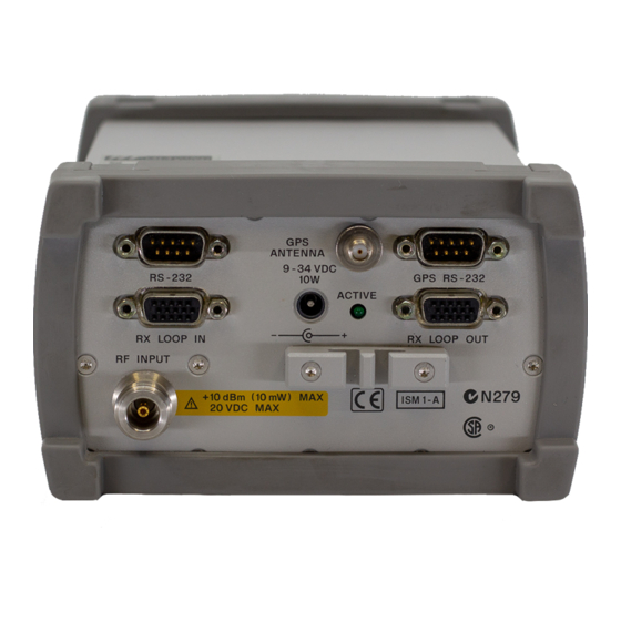
Chapter 2: Setting Up Your System Receiver Connector Panel Receiver Connector Panel Make all connections before applying power. The default serial port used by the application is COM1. If desired, you can specify a different serial port in the application. When the Agilent E645x receiver is turned on, the indicator is ACTIVE... -
Page 112: Internal Gps Receiver Connector Panel
Chapter 2: Setting Up Your System Internal GPS Receiver Connector Panel Internal GPS Receiver Connector Panel The receiver provides an internal GPS as identified in the application. Make all connections before applying power. The default serial port used by the application is COM1. If desired, you can specify a different serial port in the application. -
Page 113: Receiver To Pc Serial Port Cable Configuration
Chapter 2: Setting Up Your System Receiver to PC Serial Port Cable Configuration Receiver to PC Serial Port Cable Configuration Figure 2-30 shows the pin-out specifications for the connection between the Receiver and the PC. The cable provided with the system is a “Null Modem” cable. -
Page 114: Rs-232 To Gps Unit Cable Configuration
Chapter 2: Setting Up Your System RS-232 to GPS Unit Cable Configuration RS-232 to GPS Unit Cable Configuration Figure 2-31 is supplied in case the GPS unit you are using is different from those described in this guide. The Agilent Wireless Solutions Software can usually operate any GPS unit employing the TAIP, TSIP, or NMEA protocols. -
Page 115: Rs-232 To Differential Unit Cable Configuration
Chapter 2: Setting Up Your System RS-232 to Differential Unit Cable Configuration RS-232 to Differential Unit Cable Configuration Figure 2-32 shows the pin-out specifications for connection of the differential GPS receiver to an Agilent E645x receiver (with internal GPS). Figure 2-32 RS-232 Cable Connecting the Agilent E645x Receiver to a Differential Unit Wireless Solutions Getting Started Guide 2-93 Artisan Technology Group - Quality Instrumentation ... -
Page 116: Rx Loop In/Out Cable Configuration
Chapter 2: Setting Up Your System RX Loop In/Out Cable Configuration RX Loop In/Out Cable Configuration Figure 2-32 shows the pin-out numbers for the cable used to connect receivers, in a multiple receiver setup. Connections are made between the Rx Loop in and Rx Loop out of the Agilent E645x receivers. The pin-out numbers apply to both the short and long cables. - Page 117 Chapter 2: Setting Up Your System RX Loop In/Out Cable Configuration Wireless Solutions Getting Started Guide 2-95 Artisan Technology Group - Quality Instrumentation ... Guaranteed | (888) 88-SOURCE | www.artisantg.com...
-
Page 118: Mounting The Receiver
Chapter 2: Setting Up Your System Mounting the Receiver Mounting the Receiver The vehicle mounting kit is used to mount the Agilent digital receiver in a vehicle or rack. These parts are supplied with an Agilent digital receiver or can be ordered separately as 86154A Option 510. Figure 2-34 Vehicle Mounting Kit (Agilent 86154A Option 510) 2-96 Wireless Solutions Getting Started Guide Artisan Technology Group - Quality Instrumentation ... - Page 119 Chapter 2: Setting Up Your System Mounting the Receiver Mounting a Receiver 1. Remove the rubber bumpers from each end of the receiver. 2. To attach the brackets to the top of the receiver, remove the top two screws from the front and rear panels of the receiver. 3.
- Page 120 Chapter 2: Setting Up Your System Mounting the Receiver 2-98 Wireless Solutions Getting Started Guide Artisan Technology Group - Quality Instrumentation ... Guaranteed | (888) 88-SOURCE | www.artisantg.com...
-
Page 121: Starting And Learning To Use The Software
Starting and Learning to Use the Software Artisan Technology Group - Quality Instrumentation ... Guaranteed | (888) 88-SOURCE | www.artisantg.com... -
Page 122: What You'll Find In This Chapter
“Using the License Manager” on page 3-12 Get an online version of this guide and other “Additional Documentation” on page 3-14 documentation (PDF format). 3-2 Agilent Technologies Wireless Solutions Getting Started Guide Artisan Technology Group - Quality Instrumentation ... Guaranteed | (888) 88-SOURCE | www.artisantg.com... -
Page 123: Starting The Agilent Wireless Solutions Software
Refer to Chapter 5, “Troubleshooting Resource Problems, COM Errors and GPS Problems” for more information. Agilent Technologies Wireless Solutions Getting Started Guide 3-3 Artisan Technology Group - Quality Instrumentation ... Guaranteed | (888) 88-SOURCE | www.artisantg.com... -
Page 124: Selecting Gps Hardware
7 Select GPS, then click Modify, or double- You can now select the appropriate GPS protocol. click the GPS icon. Figure 3-2. 3-4 Agilent Technologies Wireless Solutions Getting Started Guide Artisan Technology Group - Quality Instrumentation ... Guaranteed | (888) 88-SOURCE | www.artisantg.com... - Page 125 9 Click OK when you are satisfied with the settings. 10Select Collection mode to start measurements. Figure 3-1 A List of Hardware in Configuration Mode Agilent Technologies Wireless Solutions Getting Started Guide 3-5 Artisan Technology Group - Quality Instrumentation ... Guaranteed | (888) 88-SOURCE | www.artisantg.com...
- Page 126 Starting and Learning to Use the Software Selecting GPS Hardware Figure 3-2 Hardware Editor Where You Select Your GPS Protocol 3-6 Agilent Technologies Wireless Solutions Getting Started Guide Artisan Technology Group - Quality Instrumentation ... Guaranteed | (888) 88-SOURCE | www.artisantg.com...
-
Page 127: Using The Online Tutorial
Solutions. It also demonstrates the most important tasks you’ll perform, and then guides you through practicing those tasks in the program. Agilent Technologies supplies Wireless Solutions for GSM, CDMA, and TDMA systems. This tutorial includes training for all types of systems, but it is not necessary to view all parts of the tutorial if you are only going to be analyzing your particular system. -
Page 128: Run The Tutorial
• Phone Based Procedures • Importing, exporting, and mapping data “Using Online Help” on page 3-9 for more information. 3-8 Agilent Technologies Wireless Solutions Getting Started Guide Artisan Technology Group - Quality Instrumentation ... Guaranteed | (888) 88-SOURCE | www.artisantg.com... -
Page 129: Using Online Help
Figure 3-4 shows sample lists of help topics. Figure 3-4 Online Help and How Do I Help Contents Agilent Technologies Wireless Solutions Getting Started Guide 3-9 Artisan Technology Group - Quality Instrumentation ... Guaranteed | (888) 88-SOURCE | www.artisantg.com... -
Page 130: Run The Online Help
• Double-click a book icon to view its contents. • Double-click to display the topic you want. 3-10 Agilent Technologies Wireless Solutions Getting Started Guide Artisan Technology Group - Quality Instrumentation ... Guaranteed | (888) 88-SOURCE | www.artisantg.com... - Page 131 • Double-click the topic to open the help window for that topic. 6 Click Close to exit help. The help window closes. Agilent Technologies Wireless Solutions Getting Started Guide 3-11 Artisan Technology Group - Quality Instrumentation ... Guaranteed | (888) 88-SOURCE | www.artisantg.com...
-
Page 132: Using The License Manager
Starting and Learning to Use the Software Using the License Manager Using the License Manager The hardware key that came with your Agilent Technologies system enables and secures the functionality you purchased from Agilent Technologies. Starting the License Manager Do This... -
Page 133: Learning The License Manager
Starting and Learning to Use the Software Using the License Manager Figure 3-5 License Manager Learning the License Manager For further information about the Agilent Technologies License Manager, refer to the following resources: Resource Description Online Help Available from the software’s Help menu or by pressing F1, covers all functionality. -
Page 134: Additional Documentation
CD. The documents can be found in the following location on the CD: D:\documents\ (d: represents the drive letter of your CD-ROM reader.) 3-14 Agilent Technologies Wireless Solutions Getting Started Guide Artisan Technology Group - Quality Instrumentation ... Guaranteed | (888) 88-SOURCE | www.artisantg.com... -
Page 135: Viewing And Printing Online Documents
This can be done using: • Hypertext links (blue text) • The Adobe Reader search tool, found on the Tools menu. Agilent Technologies Wireless Solutions Getting Started Guide 3-15 Artisan Technology Group - Quality Instrumentation ... Guaranteed | (888) 88-SOURCE | www.artisantg.com... - Page 136 Getting Started Guide, ensure that a page or page range is specified. The Getting Started Guide is approximately 250 pages. 3-16 Agilent Technologies Wireless Solutions Getting Started Guide Artisan Technology Group - Quality Instrumentation ... Guaranteed | (888) 88-SOURCE | www.artisantg.com...
-
Page 137: Verifying The System
Verifying the System Artisan Technology Group - Quality Instrumentation ... Guaranteed | (888) 88-SOURCE | www.artisantg.com... -
Page 138: What You Will Find In This Chapter
NOTE The verification tests are only used to alert you to possible non-operating conditions. To measure actual receiver specifications, the unit must be measured in a controlled environment, using Agilent Technologies’ prescribed measurement techniques. • Before you start the verification procedures, familiarize yourself with the system, by completing the online tutorial. -
Page 139: Method 1: Using A Signal Generator
Chapter 4: Verifying the System Method 1: Using a Signal Generator Method 1: Using a Signal Generator This procedure requires the Agilent 8648B signal generator. A similar signal generator can be used, providing it meets or exceeds the frequency ranges of your Agilent digital receiver and can produce an amplitude in the range of -70 dBm to -50 dBm. -
Page 140: Preparing The Hardware
Chapter 4: Verifying the System Method 1: Using a Signal Generator Figure 4-1 System Measurement Verification Setup Using a Signal Generator Preparing the Hardware Do This Additional Information 1 Connect the system as shown in Figure 4-1, There is a three minute delay after power-up or but do not connect the signal generator re-configuration, before the internal temperature output. -
Page 141: Preparing The Software
Chapter 4: Verifying the System Method 1: Using a Signal Generator Preparing the Software Do This Additional Information 1 Start the application program by going to the The software starts. Start menu, selecting Programs, Agilent E74xx. 2 Create a new project called We recommend you use the automatic Verification Test 1 (External generator). - Page 142 Chapter 4: Verifying the System Method 1: Using a Signal Generator Table 4-1 Signal Generator Uplink Settings Model Frequency and Power Setting GSM1900, TDMA and CDMA PCS band systems 1879 MHz at –60 dBm GSM DCS1800 band systems 1748 MHz at –60 dBm GSM900 band systems 898 MHz at –60 dBm Cellular CDMA and TDMA band systems...
-
Page 143: Testing The Signal
Chapter 4: Verifying the System Method 1: Using a Signal Generator Testing the Signal Do This Additional Information 1 In the Markers group, click Add and To Max. The level and frequency are displayed at the top-left corner of the Spectrum display. 2 In the Band group, select Downlink. - Page 144 Chapter 4: Verifying the System Method 1: Using a Signal Generator Accuracy The accuracy is calculated as: Frequency accuracy = signal generator accuracy + 1 ppm. (0.5 dB + signal generator accuracy + mismatch error ± Amplitude accuracy = + cable loss). Assuming the Agilent receiver and Agilent 8648B signal generator specifications, with nominal values of mismatch and cable losses of approximately 1 dB, you can expect:...
-
Page 145: Passing The Test
Chapter 4: Verifying the System Method 1: Using a Signal Generator Figure 4-3 Spectrum Display with Marker Set to a Center Frequency of 943 MHz (GSM900 band system) Passing the Test If the display shows a single spectral peak, and reports frequency and power levels that match the output of the signal generator, the system has passed the test. -
Page 146: Method 2: Measuring A Known Channel In The System
Chapter 4: Verifying the System Method 2: Measuring a Known Channel in the System Method 2: Measuring a Known Channel in the System Preparing the Hardware Do This Additional Information 1 Connect the system as shown in There is a three minute delay after power-up or Figure 4-4. -
Page 147: Preparing The Software
Chapter 4: Verifying the System Method 2: Measuring a Known Channel in the System Preparing the Software Do This Additional Information 1 Start the application program by going to the Start menu. The software starts. Select Programs, Agilent E74xx. 2 Create a new project called: It is recommended that you use the Verification Test 2 (Using the Antenna). -
Page 148: Testing The Signal
Chapter 4: Verifying the System Method 2: Measuring a Known Channel in the System Testing the Signal Do This See This In the Markers group, click Add and To Max. The level and frequency are displayed at the top-left corner of the Spectrum display. NOTE Wait for at least one minute before using the displayed marker value. -
Page 149: Method 3: Measuring The Noise Floor
Chapter 4: Verifying the System Method 3: Measuring the Noise Floor Method 3: Measuring the Noise Floor NOTE Use this procedure only if you do not have a signal generator and there is no known channel in the system. Connect a 50 ohm load (customer supplied) to the input of the receiver. -
Page 150: Preparing The Hardware
Chapter 4: Verifying the System Method 3: Measuring the Noise Floor Preparing the Hardware Do This Additional Information 1 Connect the system as shown There is a three minute delay after power-up or Figure 4-5 on page 4-13, using a re-configuration, before the internal temperature sensor calibrated 50Ω... -
Page 151: Preparing The Software
Chapter 4: Verifying the System Method 3: Measuring the Noise Floor Preparing the Software Do This Additional Information 1 Run the application program by going to the Start The software starts. menu, selecting Programs, Agilent E74xx. 2 Create a new project called: It is recommended that you use the automatic Verification Test 3 (Noise Floor). - Page 152 Chapter 4: Verifying the System Method 3: Measuring the Noise Floor Do This Additional Information 9 Calculate the average noise level of the downlink. Average noise level = (Marker 1 level + Marker 2 level) / 2 10 Select Uplink in the Band group. Frequency is displayed on the Spectrum VFP.
-
Page 153: Passing The Test
Chapter 4: Verifying the System Method 3: Measuring the Noise Floor NOTE The measurement is making 100 averages, which will require approximately three minutes to stabilize the noise level. After completion, stop the measurement and note the levels. Passing the Test You have passed the if the average noise level is below –122 dBm. -
Page 154: Method 4: Gps Measurement Verification Procedure
Chapter 4: Verifying the System Method 4: GPS Measurement Verification Procedure Method 4: GPS Measurement Verification Procedure NOTE If you have an Agilent digital receiver, make sure that you have tested the receiver using either method 1 (page 4-3), method 2 (page 4-10), or method 3 (page... - Page 155 Chapter 4: Verifying the System Method 4: GPS Measurement Verification Procedure In order to configure any GPS unit, you have to know the settings of that unit. The default settings of the Trimble GPS units supported by Agilent have been included in the Agilent Wireless Solutions Software.
-
Page 156: Selecting The Test
Chapter 4: Verifying the System Method 4: GPS Measurement Verification Procedure Selecting the Test Do This Additional Information 1 Start the application program by going to the The software starts. Start menu, select Programs, Agilent E74xx. 2 Create a new project called: The Measurement or Hardware configuration is Verification Test 4 (GPS). - Page 157 Chapter 4: Verifying the System Method 4: GPS Measurement Verification Procedure Figure 4-6 GPS Virtual Front Panel Display NOTE The units used for displaying the GPS statistics can be changed using the Display controls on the GPS virtual front panel. If you need to change the GPS coordinate datum, select the Advanced tab of GPS hardware configuration box.
-
Page 158: Passing The Test
Chapter 4: Verifying the System Method 4: GPS Measurement Verification Procedure Passing the Test If the display shows a clear set of satellite signals and reports the same longitude and latitude of your current location, the system passed the GPS test and is ready to be used. -
Page 159: Solving Problems And Updating Your System
Solving Problems and Updating Your System Artisan Technology Group - Quality Instrumentation ... Guaranteed | (888) 88-SOURCE | www.artisantg.com... -
Page 160: What You'll Find In This Chapter
Update the firmware. “Updating the Firmware” on page 5-12. Get telephone assistance. “Calling for Assistance” on page 5-14. Return an Agilent Technologies instrument for “Returning the Instrument for Service” on service. page 5-17. 5-2 Wireless Solutions Getting Started Guide Artisan Technology Group - Quality Instrumentation ... Guaranteed | (888) 88-SOURCE | www.artisantg.com... -
Page 161: Troubleshooting Resource Problems, Com Errors And Gps Problems
Chapter 5: Solving Problems and Updating Your System Troubleshooting Resource Problems, COM Errors and GPS Problems Troubleshooting Resource Problems, COM Errors and GPS Problems Resource Problems CAUTION It is possible to exceed Windows 95/98 allocated resource levels by opening too many windows while running your Wireless Solutions system. This will cause erratic behavior of the application and require the operator to reboot the operating system in order to recover. -
Page 162: Com Errors
Chapter 5: Solving Problems and Updating Your System Troubleshooting Resource Problems, COM Errors and GPS Problems While this application utilizes system resources, it provides a way of determining when the system is running low on available resources. Opening new windows with less than 20% remaining resources in any of the three categories could cause Windows 95/98 to overrun its resources. - Page 163 Chapter 5: Solving Problems and Updating Your System Troubleshooting Resource Problems, COM Errors and GPS Problems Do This Additional Information 1 Check the project and configuration being • Does the hardware configuration for the used by the application. project selected match the actual system hardware? •...
- Page 164 Chapter 5: Solving Problems and Updating Your System Troubleshooting Resource Problems, COM Errors and GPS Problems Do This Additional Information 2 (Continued) Check system hardware • Is DC power provided to the GPS receiver components. (external GPS)? • Is the proper RS-232 cable, or cable assembly, connected between the GPS receiver and Agilent E645x receiver (external GPS)?
- Page 165 Receiver may be in fault. Check the RS-232 cable or replace it. If the fault persists, contact Agilent Technologies. Wireless Solutions Getting Started Guide 5-7 Artisan Technology Group - Quality Instrumentation ... Guaranteed | (888) 88-SOURCE | www.artisantg.com...
-
Page 166: Locating And Eliminating Gps Errors
• Use a brand new database. Using Windows Explorer, copy the file Design.mdb found in the working directory for the application (usually \Program Files \Agilent Technologies \E74xx ), to a new file name then repeat step 4. • When nothing else works, re-install the application. - Page 167 Chapter 5: Solving Problems and Updating Your System Troubleshooting Resource Problems, COM Errors and GPS Problems settings and tape the list to the unit. The primary cause of COM errors between the PC and the GPS receiver is usually incorrect port settings. The following procedure is suggested for locating and eliminating GPS errors and problems when using the Agilent Wireless Solutions system.
- Page 168 Chapter 5: Solving Problems and Updating Your System Troubleshooting Resource Problems, COM Errors and GPS Problems Do This Additional Information 4 (Continued) Verify the GPS configuration. • Verify that the Hardware Type (for example, GPS Placer 450, 455: TAIP) is selected. If not, select the correct model and protocol in the Hardware Type field.
-
Page 169: Updating The Software
Then click on the Wireless Software Updates and Firmware Upgrades link. NOTE If you are unable to access the web, contact your Agilent Technologies representative for information about updating the software. Wireless Solutions Getting Started Guide 5-11 Artisan Technology Group - Quality Instrumentation ... Guaranteed | (888) 88-SOURCE | www.artisantg.com... -
Page 170: Updating The Firmware
Chapter 5: Solving Problems and Updating Your System Updating the Firmware Updating the Firmware Sometimes a software update (see “Updating the Software” on page 5-11) also requires a firmware update. With the software update installed, when you run the updated software and select Collection mode, you will be notified if a firmware update is required. -
Page 171: Replacement Firmware Security Key
If you have misplaced your firmware write enable key, you can order a new one (order from your Agilent Technologies representative, E6450-60007), or you can substitute a piece of wire that shorts pins 8 to 10 on the RX LOOP... -
Page 172: Calling For Assistance
Your Agilent Wireless Solutions are designed to provide dependable service. It is unlikely that you will experience a problem. However, Agilent Technologies sales and service organization is ready to provide the support you need. The Agilent Technologies web site provides very detailed lists of frequently asked questions, which address the most commonly encountered problems. -
Page 173: Frequently Asked Questions
1. Click on the Technical Support link. 2. Select the Frequently Asked Questions - Search 3. For the Search key, type the keyword "drive test" If you do not have access to the web, contact your local Agilent Technologies representative for information. Technical Telephone Assistance Your Agilent Wireless Solutions come with 12 months of technical telephone assistance and a 12 month hardware warranty period. - Page 174 Numbers to call For a more detailed list of contact numbers, please refer to the Agilent web site, or contact your local Agilent Technologies Sales and Service Office. Before calling, ensure you have all the information described in step 2, above.
-
Page 175: Returning The Instrument For Service
Agilent Technologies maintenance plan, Agilent Technologies will notify you of the cost of the repair after examining the unit. When an instrument is returned to Agilent Technologies for servicing, it must be adequately packaged (see “Preparing the Instrument for Shipping” on page 5-18) and have a complete description of the failure symptoms attached. -
Page 176: Preparing The Instrument For Shipping
3 Pack the instrument in the original shipping containers. Original materials are available through Agilent Technologies office. See step 4 for more information. 5-18 Wireless Solutions Getting Started Guide Artisan Technology Group - Quality Instrumentation ... Guaranteed | (888) 88-SOURCE | www.artisantg.com... - Page 177 Chapter 5: Solving Problems and Updating Your System Returning the Instrument for Service Do This Additional Information 4 Wrap the instrument in antistatic plastic to • For instruments weighing less than 54 kg reduce the possibility of damage caused by (120 lbs), use a double-walled, corrugated electrostatic discharge.
- Page 178 Chapter 5: Solving Problems and Updating Your System Returning the Instrument for Service 5-20 Wireless Solutions Getting Started Guide Artisan Technology Group - Quality Instrumentation ... Guaranteed | (888) 88-SOURCE | www.artisantg.com...
-
Page 179: Hardware And Software Specifications
Hardware and Software Specifications Artisan Technology Group - Quality Instrumentation ... Guaranteed | (888) 88-SOURCE | www.artisantg.com... -
Page 180: What You'll Find In This Chapter
Specifications Agilent E7490A Over Air Maintenance Test “Software Measurement Specifications” on Software Measurement Specifications page 6-25 Agilent E7473A and Agilent E7490A Cellular and “Hardware Specifications” on page 6-30 PCS CDMA Wireless Solutions Hardware Specifications TDMA Agilent E7474A Cellular and PCS TDMA “Software Measurement Specifications”... -
Page 181: Wireless Solutions Getting Started Guide Contents-3
To maintain specifications, periodic recalibrations are necessary. We recommend that the Receiver be calibrated at an Agilent Technologies service facility every 12 months. Wireless Solutions Getting Started Guide 6-3 Artisan Technology Group - Quality Instrumentation ... Guaranteed | (888) 88-SOURCE | www.artisantg.com... -
Page 182: General System Software Specifications And Functionality
Chapter 6: Hardware and Software Specifications General System Software Specifications and Functionality General System Software Specifications and Functionality Some of the functionality of the system is common across all platforms. The following sections describe the specifications and functionality of these cross-platform features. - Page 183 Chapter 6: Hardware and Software Specifications General System Software Specifications and Functionality Export Plan Element Description Processing functions Defines the functions that will be applied to the data during export. Exclusion rules Defines a set of conditions that, if true, the associated data will be excluded from the export.
- Page 184 Chapter 6: Hardware and Software Specifications General System Software Specifications and Functionality • Bin by location (grid binning) Define the reference bin to be used, choices are: • Southwest extent of drive data • Southeast extent of drive data • Northwest extent of drive data •...
- Page 185 Chapter 6: Hardware and Software Specifications General System Software Specifications and Functionality Optional Data parameters • Position • Altitude • Time • Date • Fill column data • Column headings Position Formats • Decimal degrees with direction • Deg: Min: Sec with direction •...
-
Page 186: Alerts And Alarms
Chapter 6: Hardware and Software Specifications General System Software Specifications and Functionality Integrated Mapping Software MapInfo can be run from within the system software. The system can also export data in ASCII format. The data can then be imported into other applications. - Page 187 Chapter 6: Hardware and Software Specifications General System Software Specifications and Functionality Actions (Alarms and Alerts) • Play a .WAV audio file • Display a text message • Pause or stop measurements Alert Conditions • Greater than (>) • ≥ Greater than or equal to ( •...
-
Page 188: Link Editor
Chapter 6: Hardware and Software Specifications General System Software Specifications and Functionality • Subset • • • XOR (exclusive OR) Any measurement can be an operand in an alert or alarm. Below are some examples (Agilent E7473A CDMA system example shown) to illustrate alerts and alarms. -
Page 189: Real-Time Mapping (Option 160)
Collection mode. The reports generated are in HTML format with referenced images, which are captured in PNG format. The reports and images are stored in the report folder (C:\Program Files\Agilent Technologies\E74xx\Reports\reportname\). The following details can be entered by the user: •... -
Page 190: Virtual Front Panel Printing
Chapter 6: Hardware and Software Specifications General System Software Specifications and Functionality • User name • Company name • Time report generated. By default, this is the PC system time. • Date. By default, this is the PC system date. •... -
Page 191: Indoor Measurements (Option 180)
Chapter 6: Hardware and Software Specifications General System Software Specifications and Functionality Indoor Measurements (Option 180) The Agilent Wireless Solutions Software can be used for testing and measuring indoor coverage areas. These measurements are taken without reference to GPS or dead-reckoning position information. An indoor system supports the following hardware: •... -
Page 192: Agilent E7473A Cdma System Specifications
Chapter 6: Hardware and Software Specifications Agilent E7473A CDMA System Specifications Agilent E7473A CDMA System Specifications Software Measurement Specifications The Agilent E7473A measurement software has the following measurement capabilities and functionality: • “CDMA Pilot Channel Analysis” on page 6-14 • “CW Power Measurements”... - Page 193 Chapter 6: Hardware and Software Specifications Agilent E7473A CDMA System Specifications • Top N The system measures all of the pilots in the network and returns the ‘N’ Strongest pilot channels received, where ‘N’ is a user definable integer from 1 to 20. The results are displayed in bar graph format.
- Page 194 Chapter 6: Hardware and Software Specifications Agilent E7473A CDMA System Specifications Ec/Io • Show value (bar graphs only) Peak Ec/Io Peak Ec Aggregate Ec/Io Aggregate Ec Aggregate - Peak Delay Spread(Chips) Pilot delay (Chips) Measurement Results • Peak Ec/Io • Peak Ec •...
- Page 195 Chapter 6: Hardware and Software Specifications Agilent E7473A CDMA System Specifications short-code pattern synchronous with the GPS even second clock. If the signal is received 3 chips after the GPS even second clock, then the pilot delay is said to be 3 chips (1 chip = 0.8 microseconds). Timing offsets can be due to both propagation delay and base station timing problems.
- Page 196 Chapter 6: Hardware and Software Specifications Agilent E7473A CDMA System Specifications • Resolution Bandwidth (CW power, all other options) 8.36 kHz to 1 MHz in wideband mode 246 Hz to 28 kHz in narrowband mode • Resolution bandwidth (CW power, Option 390 and 391 only) 8.36 kHz to 950 kHz in wideband mode 1.68 kHz to 190 kHz in narrowband mode Channel Power Measurements...
- Page 197 Chapter 6: Hardware and Software Specifications Agilent E7473A CDMA System Specifications • IF Bandwidth Wideband mode - 1.25 MHz Narrowband mode - 30 kHz or 200 kHz (options 390 and 391 only) • Resolution bandwidth (CW power only) 8.36 kHz to 1 MHz in wideband mode 246 Hz to 28 kHz in narrowband mode •...
- Page 198 Chapter 6: Hardware and Software Specifications Agilent E7473A CDMA System Specifications Agilent E7473A Option 300/310 824 - 849 MHz [819 - 854 MHz] 869 - 894 MHz [864 - 899 MHz] Agilent E7473A Option 380/381 832 - 870 MHz [827 - 875 MHz] 887 - 925 MHz [882 - 930 MHz] Agilent E7473A Option 390/391 1710 - 1785 MHz [1705 - 1790 MHz]...
- Page 199 Chapter 6: Hardware and Software Specifications Agilent E7473A CDMA System Specifications CDMA Phone functionality Part of Agilent E7473A Option 100, 120, 150. The phone component of the Agilent E7473A system includes three main functions. Each one is associated with a control/display window called a virtual front panel.
- Page 200 Chapter 6: Hardware and Software Specifications Agilent E7473A CDMA System Specifications Markov (set 1 or set 2) Loopback (8 or 13 kbps) Enhanced Variable Rate Codec (EVRC) State Controls • No analog (forces dual mode phone to stay in digital mode) •...
- Page 201 Chapter 6: Hardware and Software Specifications Agilent E7473A CDMA System Specifications CDMA Phone Measurement Data The Agilent E7473A system extracts various measurement data from the mobile handset. You control extraction of the specific measurement types with a set of check boxes. The data types are listed below. Display fields (text) •...
- Page 202 Chapter 6: Hardware and Software Specifications Agilent E7473A CDMA System Specifications CDMA Phone Messaging The Agilent E7473A system extracts and decodes the over-the-air messaging from the handset. The user can select any or all of the channel types listed below from which to extract and decode messaging. Message logging controls •...
-
Page 203: Agilent E7490A And Agilent E7473A Cdma System Specifications
The system measures all signals in the network and returns the ‘N’strongest power pilot signals received, where ‘N’ is a user definable integer from 1 to 2 for Agilent E7490A and ‘N’ is from 1 to 20 for Agilent E7473A. The results are displayed in bar graph format. - Page 204 Chapter 6: Hardware and Software Specifications Agilent E7490A and Agilent E7473A CDMA System Specifications • All (both) Measurement Controls • Carrier frequency Frequency Channel • Measurement types Top N CDP trace CDP stats and CDP reset PN increment • Band...
- Page 205 Average across all active channels All lists CDMA Base Station Spectrum Analysis Part of Agilent E7490A and Agilent E7473A option 111. The spectral mask measurement enables you to visually determine whether the signals in your band meet the IS-97C specifications.
- Page 206 • Marker to center CDMA Mobile Station Test Measurement (MOST) Part of Agilent E7490A and Agilent E7473A option 101. The Mobile station test measurement (MOST) measures quality, automates the measurement actions, and records the results of the measurement. You enter the call number, the length of the call, and the code key sequence. The MOST test forces the phone to hand the call to the next channel element.
- Page 207 Chapter 6: Hardware and Software Specifications Agilent E7490A and Agilent E7473A CDMA System Specifications • Redial interval (wait duration after drop or block) • Maximum redial attempts Call Test Setup Fields Directory number Function code Test interval Number of iterations Wireless Solutions Getting Started Guide 6-29 Artisan Technology Group - Quality Instrumentation ...
-
Page 208: Hardware Specifications
Chapter 6: Hardware and Software Specifications Agilent E7490A and Agilent E7473A CDMA System Specifications Hardware Specifications For full details on receiver types and options, refer to the online Agilent System Options and Accessories Guide. For more information on viewing and printing this guide, refer to “Viewing and Printing Online Documents”... - Page 209 Chapter 6: Hardware and Software Specifications Agilent E7490A and Agilent E7473A CDMA System Specifications Model E6452A Receiver E6452A-H02 Options 300, 310 Options 380, 381 Adjacent channel –25 dBm typical desensitization Adjacent channel 45 dB typical rejection Internally generated –120 dBm...
- Page 210 Chapter 6: Hardware and Software Specifications Agilent E7490A and Agilent E7473A CDMA System Specifications Agilent E7473A and Agilent E7490A Option 320/330, 390/391 PCS Receiver Specifications Model E6450B Receiver E6453A Receiver Options 320, 330 Options 390, 391 Frequency Frequency range 1850 to 1910 MHz...
- Page 211 Chapter 6: Hardware and Software Specifications Agilent E7490A and Agilent E7473A CDMA System Specifications Model E6450B Receiver E6453A Receiver Options 320, 330 Options 390, 391 Input/Output RF input 50Ω Type-N Connectors Computer RS-232 (DB9) Male RS-232 (DB9) Male Power DC power jack 100 mils, positive center...
-
Page 212: Agilent E7474A Tdma System Specifications
Chapter 6: Hardware and Software Specifications Agilent E7474A TDMA System Specifications Agilent E7474A TDMA System Specifications Software Measurement Specifications The Agilent E7474A measurement software has the following measurement capabilities and functionality: • “TDMA Channel Analyzer” on page 6-34 • “TDMA Interference Analysis” on page 6-35 •... - Page 213 Chapter 6: Hardware and Software Specifications Agilent E7474A TDMA System Specifications • User list The user manually inputs a list of up to 40 channels to be measured. The measurements are displayed in bar graph format with up to 20 bars. If more than 20 channels are in the list, all channels are measured and recorded, but only 20 are displayed.
- Page 214 Chapter 6: Hardware and Software Specifications Agilent E7474A TDMA System Specifications handed-off to a new channel, the adjacent channel interference measurement tunes to the new channel. The adjacent channel interference measurement can also be used independently from the phone. A user can define a specific channel to measure along with the associated upper and lower adjacent channels.
- Page 215 Chapter 6: Hardware and Software Specifications Agilent E7474A TDMA System Specifications Frequency Entry Methods • List Enter an arbitrary list of frequencies. • Trace Enter a start frequency, step size, and count. The system measures at the start frequency, at the (start + step) frequency, (start + (count - 1)*step frequency.
- Page 216 Chapter 6: Hardware and Software Specifications Agilent E7474A TDMA System Specifications at the start frequency, at the (start + step) frequency,..., (start + (count - 1*step) frequency. For example, if the start frequency is set to 1900 MHz, the step size is set to 1 MHz, and the count is set to 4; the measurements are made at 1900 MHz, 1901 MHz, 1902 MHz and 1903 MHz.
- Page 217 Chapter 6: Hardware and Software Specifications Agilent E7474A TDMA System Specifications 824 - 849 MHz [819 - 854 MHz] 869 - 894 MHz [864 - 899 MHz] • Frequency, tunable range PCS band receiver, Options 320, 330 1850 - 1910 MHz [1845 - 1915 MHz] 1930 - 1990 MHz [1925 - 1995 MHz] •...
- Page 218 Chapter 6: Hardware and Software Specifications Agilent E7474A TDMA System Specifications called a virtual front panel. For the phone measurement data, there are two additional displays for data in different formats. • Phone control (see page 6-40) • Phone measurement data (see page 6-41) Large display virtual front panel (see...
- Page 219 Chapter 6: Hardware and Software Specifications Agilent E7474A TDMA System Specifications Statistics logging controls • Attempted calls • Dropped calls • Blocked calls (failed originations) In addition to control functionality, the phone control virtual front panel displays the information listed below. Display fields (text) •...
- Page 220 Chapter 6: Hardware and Software Specifications Agilent E7474A TDMA System Specifications • Mobile data State Mode (TDMA, analog) • Best MAHO Channel RSSI • System data System identification (SID) Home or roam Provider Bar graph displays • Serving channel • MAHO channels Line graph displays •...
- Page 221 Chapter 6: Hardware and Software Specifications Agilent E7474A TDMA System Specifications • • Color code • Site • State (conversation, idle, etc.) • Status (TDMA, Analog, etc.) • • • Best MAHO channel • Best MAHO RSSI • Home or roam •...
- Page 222 Chapter 6: Hardware and Software Specifications Agilent E7474A TDMA System Specifications TDMA Phone Messaging The Agilent E7474A system extracts and decodes the layer 3 over-the-air messaging from the handset. The user can select any or all of the message types listed below from which to extract and decode messaging. Message type selection controls •...
-
Page 223: Hardware Specifications
Chapter 6: Hardware and Software Specifications Agilent E7474A TDMA System Specifications Hardware Specifications For full details on receiver types and options, refer to the online Agilent System Options and Accessories Guide. For more information on view and printing this guide, refer to “Viewing and Printing Online Documents”... - Page 224 Chapter 6: Hardware and Software Specifications Agilent E7474A TDMA System Specifications Model E6452A Receiver, Options 300, 310 Adjacent channel –25 dBm typical desensitization Adjacent channel 45 dB typical rejection Internally generated –120 dBm spurious, input referred Input/Output RF input 50Ω Type-N Connectors Computer RS-232 (DB9) Male...
- Page 225 Chapter 6: Hardware and Software Specifications Agilent E7474A TDMA System Specifications Agilent E7474A Option 320, 330 PCS Receiver Specifications Model E6450B Receiver Options 320, 330 Frequency Frequency range 1850 to 1910 MHz 1930 to 1990 MHz Frequency accuracy ±1 ppm With GPS time ±0.05 ppm, characteristic synchronization...
- Page 226 Chapter 6: Hardware and Software Specifications Agilent E7474A TDMA System Specifications Model E6450B Receiver Options 320, 330 Connectors Computer RS-232 (DB9) Male RS-232 (DB9) Male Power DC power jack 100 mils, positive center Miscellaneous Operating 0°C to 55°C temperature range Maximum relative 80% for temperatures up to 31°C, decreasing linearly humidity...
-
Page 227: Agilent E7475A Gsm900, Dcs1800 And Gsm1900 System Specifications
Chapter 6: Hardware and Software Specifications Agilent E7475A GSM900, DCS1800 and GSM1900 System Specifications Agilent E7475A GSM900, DCS1800 and GSM1900 System Specifications Software Measurement Specifications The Agilent E7475A measurement software has the following measurement capabilities and functionality: • “GSM Broadcast Channel Analysis” on page 6-49 •... - Page 228 Chapter 6: Hardware and Software Specifications Agilent E7475A GSM900, DCS1800 and GSM1900 System Specifications • Top N The system measures all of the GSM channels in the user selected range and returns the N strongest GSM channels received. N is a user-defined variable from 1 to 20. The results are displayed in a bar graph of amplitude versus frequency or a line graph of amplitude versus time.
- Page 229 Chapter 6: Hardware and Software Specifications Agilent E7475A GSM900, DCS1800 and GSM1900 System Specifications Markers (Trace Displays only) • Multiple markers • Delta Markers • To Max function • Drag and drop Display Controls • Power Display (Y-axis parameter) RxLev •...
- Page 230 Chapter 6: Hardware and Software Specifications Agilent E7475A GSM900, DCS1800 and GSM1900 System Specifications two, user-selectable channels, it can return the ratio in dB of the power in each channel to that in the immediately adjacent channels. • Co-Channel measurement: For a single-user, selectable channel, the system can return: Total power in the channel Carrier to interferer ratio...
- Page 231 Chapter 6: Hardware and Software Specifications Agilent E7475A GSM900, DCS1800 and GSM1900 System Specifications Primary BSIC and cellsite name Secondary BSIC and cellsite name Status of measurement • Symbol Delay Spread (multi-path) graph • ± Power at 6 symbol offsets CW Power Measurements Part of Agilent E7475A Option 110, 120.
- Page 232 Chapter 6: Hardware and Software Specifications Agilent E7475A GSM900, DCS1800 and GSM1900 System Specifications Channel Power Measurements Part of Agilent E7475A Option 110, 120. The Agilent E7475A system can measure the total power (Channel Power) within a user-defined bandwidth at a user-defined set of frequencies. This differs from the CW power measurement in that the total power is integrated across the specified channel width.
- Page 233 Chapter 6: Hardware and Software Specifications Agilent E7475A GSM900, DCS1800 and GSM1900 System Specifications 5 kHz to 75 MHz in narrowband mode GSM1900 (option 340, 350) 30 kHz to 60 MHz in wideband mode 5 kHz to 60 MHz in narrowband mode Spectrum Measurements Part of Agilent E7475A Option 110, 120.
- Page 234 Chapter 6: Hardware and Software Specifications Agilent E7475A GSM900, DCS1800 and GSM1900 System Specifications GSM1900 (option 340, 350) - 70 MHz • IF Bandwidth 1.25 MHz (wideband mode) 200 kHz (narrowband mode) • Resolution Bandwidth 8.36 kHz to 950 kHz in wideband mode 1.68 kHz to 190 kHz in narrowband mode Markers •...
- Page 235 Chapter 6: Hardware and Software Specifications Agilent E7475A GSM900, DCS1800 and GSM1900 System Specifications Total channel power. • Broadcast channel and adjacent channel analyzer Power averaged over 8 timeslots. Peak power measurement. • Broadcast channel with BSIC decoding Power is measured over 1 timeslot. •...
- Page 236 Chapter 6: Hardware and Software Specifications Agilent E7475A GSM900, DCS1800 and GSM1900 System Specifications GSM Phone functionality Part of Agilent E7475A Option 100, 120, 150. The phone component of the Agilent E7475A system includes four main functions. • Phone Call Control (see page 6-58) •...
- Page 237 Chapter 6: Hardware and Software Specifications Agilent E7475A GSM900, DCS1800 and GSM1900 System Specifications Enhanced full rate of speech (if supported by network) • Select channel Force handover to an ARFCN Prevent handover from an ARFCN Force broadcast channel (BCH) •...
- Page 238 Chapter 6: Hardware and Software Specifications Agilent E7475A GSM900, DCS1800 and GSM1900 System Specifications GSM Phone Measurement Data The Agilent E7475A system extracts various measurement data from the mobile handset. You control extraction of the specific measurement types with a set of check boxes. The data types are listed below. Display fields (text) •...
- Page 239 Chapter 6: Hardware and Software Specifications Agilent E7475A GSM900, DCS1800 and GSM1900 System Specifications RxLev versus time (Can be displayed as RxLev-sub or RxLev-full.) Tx power versus time Timing advance versus time GSM Phone Messaging The Agilent E7475A system extracts and decodes the Layer 3 over-the-air messaging from the handset.
- Page 240 Chapter 6: Hardware and Software Specifications Agilent E7475A GSM900, DCS1800 and GSM1900 System Specifications GSM Phone Scan Measurements Part of Agilent E7475A Option 130 The Agilent E7475A system enables the phone to switch into a scanning mode and to pass these measurements for display and recording. The mobile scans all broadcast channels Measurement Types •...
- Page 241 Chapter 6: Hardware and Software Specifications Agilent E7475A GSM900, DCS1800 and GSM1900 System Specifications • Drag and drop Display Controls • Power display (Y-axis parameter) RxLev • Display mode Amplitude versus frequency Amplitude versus Time • Show value (bar graphs only) Power (dBm) Power in RxLev Measurement Results...
-
Page 242: Hardware Specifications
Chapter 6: Hardware and Software Specifications Agilent E7475A GSM900, DCS1800 and GSM1900 System Specifications Hardware Specifications For full details on receiver types and options, refer to the online Agilent System Options and Accessories Guide. For more information on view and printing this guide, refer to “Viewing and Printing Online Documents”... - Page 243 Chapter 6: Hardware and Software Specifications Agilent E7475A GSM900, DCS1800 and GSM1900 System Specifications Model Agilent E7475A Agilent E7475A Agilent E7475A Option 300, 310 Option 320, 330 Option 340, 350 (E6451A) (E6453A) (E6454A) Connectors Computer RS-232 (DB9) Male RS-232 (DB9) Male Power DC power jack 100 mils, positive center...
- Page 244 Chapter 6: Hardware and Software Specifications Agilent E7475A GSM900, DCS1800 and GSM1900 System Specifications HP E7475A Options 305 Receiver Specifications Model Agilent E7475A Option 305 (E6451A-E03) Frequency Frequency range 876 to 915 MHz 921 to 960 MHz Frequency accuracy ±1 ppm IF bandwidth 1.25 MHz, characteristic (wideband mode) 200 kHz, characteristic (narrowband mode)
- Page 245 Chapter 6: Hardware and Software Specifications Agilent E7475A GSM900, DCS1800 and GSM1900 System Specifications Model Agilent E7475A Option 305 (E6451A-E03) Connectors Computer RS-232 (DB9) Male RS-232 (DB9) Male Power DC power jack 100 mils, positive center Miscellaneous Operating temperature 0°C to 55°C range Maximum relative 80% for temperatures up to 31°C, decreasing linearly to...
-
Page 246: General Hardware Specifications And Minimum System Requirements
Chapter 6: Hardware and Software Specifications General Hardware Specifications and Minimum System Requirements General Hardware Specifications and Minimum System Requirements Personal Computer Recommendations, Minimum The PC requirements differ depending on the operating system, and on whether you wish to collect data from a single phone or multiple phones. Single phone •... -
Page 247: Supported Phones
Any external GPS will have to output a GPS 1 pulse/second signal for Pilot correlation for Agilent E7473A options 110, 111, or 120 and Agilent E7490A option 111. Wireless Solutions Getting Started Guide 6-69 Artisan Technology Group - Quality Instrumentation ... Guaranteed | (888) 88-SOURCE | www.artisantg.com... -
Page 248: Gps Systems Supported
Chapter 6: Hardware and Software Specifications General Hardware Specifications and Minimum System Requirements GPS Systems Supported • Bosch Travel Pilot RGS08 Professional • Magneti Marelli RP Nav200 • GARMIN GPSII/III • Trimble DR • Trimble 455/DR and 450 • Trimble SVeeSix •... -
Page 249: Safety And Regulatory Information
Safety and Regulatory Information Artisan Technology Group - Quality Instrumentation ... Guaranteed | (888) 88-SOURCE | www.artisantg.com... -
Page 250: Warning And Caution Notices
Chapter 7: Safety and Regulatory Information Warning and Caution Notices Warning and Caution Notices Review this product and related documentation to familiarize yourself with safety markings and instructions before you operate the system. This product has been designed and tested in accordance with appropriate international standards. -
Page 251: Instrument Markings
Chapter 7: Safety and Regulatory Information Warning and Caution Notices Instrument Markings When you see this symbol on your instrument, you should refer to the instrument’s instruction manual for important information. This symbol indicates hazardous voltages. The laser radiation symbol is marked on products that have a laser output. This symbol indicates that the instrument requires alternating current (ac) input. -
Page 252: General Safety Considerations
(in which all means for protection are intact) only. • No operator serviceable parts are inside this system. Refer servicing to a qualified Agilent Technologies, Inc. service center. To prevent electrical shock, do not remove the covers. • To prevent electrical shock, disconnect the Agilent receiver from mains before cleaning. -
Page 253: Product Installation, Use, And Storage
Chapter 7: Safety and Regulatory Information General Safety Considerations Product Installation, Use, and Storage • CAUTIONS This Agilent digital receiver is designed for use in INSTALLATION CATEGORY II and POLLUTION DEGREE 2, per IEC 1010 and 664 respectively. • Enclosure protection IP40 according to IEC 529. •... -
Page 254: Declarations Of Conformity
Chapter 7: Safety and Regulatory Information Declarations of Conformity Declarations of Conformity 7-6 Wireless Solutions Getting Started Guide Artisan Technology Group - Quality Instrumentation ... Guaranteed | (888) 88-SOURCE | www.artisantg.com... - Page 255 Chapter 7: Safety and Regulatory Information Declarations of Conformity Wireless Solutions Getting Started Guide 7-7 Artisan Technology Group - Quality Instrumentation ... Guaranteed | (888) 88-SOURCE | www.artisantg.com...
- Page 256 Chapter 7: Safety and Regulatory Information Declarations of Conformity 7-8 Wireless Solutions Getting Started Guide Artisan Technology Group - Quality Instrumentation ... Guaranteed | (888) 88-SOURCE | www.artisantg.com...
- Page 257 6-49 Analysis, 6-27 Datum Agilent E748xx Post-Processing CDMA Code Domain Power AGD66, Software, Analysis, 6-25 AGD84, Agilent E7490A system CDMA Mobile Station Test European, specification, 6-25 Measurement (MOST), 6-28 Hu-Tzu-Chan, Agilent Technologies web site, 5-15 CDMA pilot channel analysis, 6-14...
- Page 258 Index European coordinate datum, hardware learning how to use the software, export column delimiters, automatic configuration, License Manager Export position formats, configuring, adding product options, selecting GPS, learning, 3-13 hardware installation tips, starting, 3-12 hardware security key, transfer options, heading sensor, 2-51 3-10 configuring,...
- Page 259 Index phone control, 6-40 differential GPS, 6-70 call controls, 6-21, 6-40, 6-58 external GPS, 6-69 NAD27, state controls, 6-22 mapping software, NAD83, statistics logging controls, 6-22, resource levels, noise floor frequency setting, 4-16 6-59 resource meter, noise level phone functionality, 6-58 returning for service, 5-17...
- Page 260 Agilent E7473A, 6-14 wires, 2-58 yellow wire, 2-14, 2-36 Agilent E7474A, 6-34 tutorial, Agilent E7475A, 6-49 type-N to TNC adapter, 2-23, 2-45, Agilent E7490A, 6-25 typical installation, technical telephone assistance, 5-15 Tokyo (J6), update Tokyo-Korea, firmware, 5-12 transform coordinates, 2-12...
- Page 261 Artisan Technology Group is your source for quality new and certified-used/pre-owned equipment SERVICE CENTER REPAIRS WE BUY USED EQUIPMENT • FAST SHIPPING AND DELIVERY Experienced engineers and technicians on staff Sell your excess, underutilized, and idle used equipment at our full-service, in-house repair center We also offer credit for buy-backs and trade-ins •...