Kensa Heat Pumps Shoebox Installation And Commissioning Manual
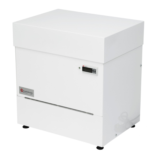
Shoebox heat pump (slinkies)
Hide thumbs
Also See for Shoebox:
- User manual (20 pages) ,
- Installation manual (40 pages) ,
- Installation, commissioning and user manual (42 pages)
Table of Contents
Advertisement
Quick Links
See also:
User Manual
Advertisement
Table of Contents

Related Manuals for Kensa Heat Pumps Shoebox


Summary of Contents for Kensa Heat Pumps Shoebox
- Page 1 Manual Shoebox Heat Pump (Slinkies) Installation and Commissioning Manual Copyright ©2017 Kensa Heat Pumps Ltd Shoebox Heat Pump Manual (Slinkies) Version 4 Page 1 of 42...
-
Page 2: Table Of Contents
4.6.1......Single Underfloor Control Unit ................22 4.6.2 ....... Multiple Underfloor Control Units ................23 4.6.3....... Radiator with Thermostat ..................23 4.6.4......DHW time clock and 3 way diverting valve wiring ..........24 Shoebox Heat Pump Manual (Slinkies) Version 4 Page 2 of 42... - Page 3 7.1.4......General exceptions ....................40 7.1.5......Care of Duty ......................41 7.1.6......In the event of Damage ..................41 7.1.7......Replacement Parts....................41 8....... Heat pump settings sheet ............. 44 Shoebox Heat Pump Manual (Slinkies) Version 4 Page 3 of 42...
-
Page 4: Introduction
Simon Lomax Managing director Kensa Heat Pumps Ltd For further information on ground source heat pumps and their application, please refer to www.kensaheatpumps.com Shoebox Heat Pump Manual (Slinkies) Version 4 Page 4 of 42... -
Page 5: Safety Information
Kensa offer a life time decommissioning service for this product. This is available on a return to base basis (carriage at users’ cost). Disposal of any antifreeze water mix should follow the disposal instructions as laid out on the COSH Safety Data Sheet available on request. Shoebox Heat Pump Manual (Slinkies) Version 4 Page 5 of 42... -
Page 6: General Product Information
It is ideally suited to multi flat developments using a communal ground borehole field. In addition, and if required, the Kensa Shoebox can also provide domestic hot water. Heat pumps can provide lower running costs and will generate significantly lower carbon emissions compared with traditional fossil fuels. -
Page 7: Kensa Compact Technical Data
Shoebox Heat Pump Manual (Slinkies) Version 4 Page 7 of 42... -
Page 8: Installation
IEE regulations. Any plumbing work should be carried out to local water authority and WRC regulations. 4.1 The Golden Rules of Installing a Shoebox Heat Pump Connect the heat pump using only plastic pipe or flexible piping. -
Page 9: Underfloor With A Single Manifold. Space Heating Only
Fig 2 Heat Pump with Under- floor and a Single Manifold Schematic 4.2.2 Under-floor with a multiple manifolds. Space heating only Fig 3 Heat Pump with Under-floor and Multiple Manifolds Schematic Shoebox Heat Pump Manual (Slinkies) Version 4 Page 9 of 42... -
Page 10: Radiators. Space Heating Only
DHW mode until 2 hours has passed. Please contact Kensa if this time period needs to be adjusted . The maximum DHW temperature that the heat pump can achieve will be approximately 60 Shoebox Heat Pump Manual (Slinkies) Version 4 Page 10 of 42... -
Page 11: Type Of Dhw Tank
It is also possible to use trace heating tape, this removes the additional cost of installation of the secondary return and water pump and the associated running costs of this equipment. Shoebox Heat Pump Manual (Slinkies) Version 4 Page 11 of 42... - Page 12 Fig 5 Under-floor with a single manifold and DHW Schematic Fig 6 Under-floor with multiple manifolds and DHW Schematic Note: Additional circulation pumps with multiple manifolds depends on the system design. Shoebox Heat Pump Manual (Slinkies) Version 4 Page 12 of 42...
- Page 13 The above schematic shows how a buffer vessel can be incorporated into the shoebox installation without the need of a second water pump. The buffer vessel allows all radiators or under-floor zones to be fully controlled and prevents the shoebox from short cycling, hence removing the need for ‘open’ zones.
-
Page 14: Mechanical Installation
Check the appliance for transport damage. Under no circumstances should a damaged appliance be operated or installed. -
Page 15: Installation Of The Heat Pump
Kensa Supply Fig 10 Manifold Slinky connections Remove the top of the shoebox heat pump. This is connected via magnets so a short sharp pull of the top forward and up will release this. Fig 11 Shoebox heat pump top panel... - Page 16 ,(which must be connected the correct way round) according to the Illustration be- low. Flexible hoses are provided with the shoebox to aid in the installation. These hoses should not be directly connected to the connections on the heat pump but used between rigid pipe (i.e. an elbow) connected at the heat pump and the distribution systems (see Fig 13).
-
Page 17: Meter Installation
The required length of straight pipe-work between isolation valves is 20 times the pipe Shoebox Heat Pump Manual (Slinkies) Version 4 Page 17 of 42... - Page 18 3. Leave sufficient pipe-work accessible, i.e. not boxed in or under floor boards, to enable meters to be fitted; Fig 15 Typical 2 Pipe Heat Meter Installation Shoebox Heat Pump Manual (Slinkies) Version 4 Page 18 of 42...
- Page 19 Therefore, at the same time as installing isolation valves for the heat meters, installers should consider the placement of an easily-accessible electricity supply to power the heat meters. Shoebox Heat Pump Manual (Slinkies) Version 4 Page 19 of 42...
- Page 20 This page is intentionally blank Shoebox Heat Pump Manual (Slinkies) Version 4 Page 20 of 42...
-
Page 21: Electrical Installation
4.6 Electrical Installation The Kensa ’Shoebox’ heat pump range is available in single phase power supply versions and the single compressor is fitted with fly lead. Any electrical work required to install or maintain this appliance should be carried out by a suitably... -
Page 22: Single Underfloor Control Unit
Enable Signal connection is supplied with a temporary link across it . This should be removed after commissioning and connection to the heating control system. (Terminals 1 and 2) Shoebox Heat Pump Manual (Slinkies) Version 4 Page 22 of 42... -
Page 23: Multiple Underfloor Control Units
Heat Pump Enable Signal No Call 0-50V Call >120V 50V < Call voltages < 120V are not permitted Enable Signal link removed Heat Pump Wiring Terminal block Shoebox Heat Pump Manual (Slinkies) Version 4 Page 23 of 42... -
Page 24: Dhw Time Clock And 3 Way Diverting Valve Wiring
Heat Pump Wiring Terminal block Fig 22 Heat Pump Wiring—DHW Note: The hot water cylinder high limit stat maybe required to be wired into the live return from the DHW Heating Time Clock. Shoebox Heat Pump Manual (Slinkies) Version 4 Page 24 of 42... - Page 25 This page is left intentionally blank Shoebox Heat Pump Manual (Slinkies) Version 4 Page 25 of 42...
-
Page 26: Commissioning
Clarke SPE1200SS pump as above. The water level in the dustbin will need to be topped up constantly during the following process. The pump may need priming by pouring water into its priming port until it overflows. Shoebox Heat Pump Manual (Slinkies) Version 4 Page 26 of 42... - Page 27 Start the purge pump, being careful that the water pipe returning water to the dustbin is secure. If the water level in the dustbin does not start to drop, then repeat the pump priming. No water Shoebox Heat Pump Manual (Slinkies) Version 4 Page 27 of 42...
-
Page 28: Adding Antifreeze For Multiple Slinkies
The level needs to drop to about 200 to 250mm. Take care that the suction pipe remains covered with water to stop any air being admitted into the system. Shoebox Heat Pump Manual (Slinkies) Version 4 Page 28 of 42... - Page 29 COSH. Allow the solution to settle for a few moments to allow any trapped air to escape. Ensure the valves on the shoebox ground array connections are open. Open the valve V1 to the heat pump and start the purge pump to circulate the antifreeze around the system. Leave the pump run- ning until antifreeze is seen returning to the dustbin.
-
Page 30: Pressure Testing In Accordance To Bs805 Section 11.3.3.4
Sudden pressure drop of at least 10% of the test pressure 10 mins. First pressure measurement 20 mins. Second pressure measurement 30 mins. Third and final pressure measurement Shoebox Heat Pump Manual (Slinkies) Version 4 Page 30 of 42... -
Page 31: Purging Procedure And Adding Antifreeze For Single Slinkies
The manifold allows the slinky to be filled and purged. To/From Heat Pump 28mm OD Fig 30 Single Slinky Manifold Return Purge/Fill Connection Return Purge/Fill Connection To/From Slinky 28mm OD Shoebox Heat Pump Manual (Slinkies) Version 4 Page 31 of 42... - Page 32 Both slinky connections are now closed. Purge ports open to heat pumps. Start the pump and purge the heat pump of air. Shoebox Heat Pump Manual (Slinkies) Version 4 Page 32 of 42...
-
Page 33: Testing Of Antifreeze Concentration
The concentration of antifreeze is required for the commissioning certificate and it is advised that this figure is noted in the settings table. To comply with MCS guidelines two random samples of anti-freeze concentration should be taken when the unit is commissioned. Shoebox Heat Pump Manual (Slinkies) Version 4 Page 33 of 42... -
Page 34: Heating Distribution And Load Side Purging
5.1 .5 Heating distribution and load side purging Find the cold fill for the heating system and open the valve on the heating system to allow water into the heating system and the Shoebox. Ensure a load side water pump is fitted and operational. -
Page 35: Heat Pump Operation
Do not try to spin the impellor with the power on. Fig 33 Spinning the pump Disconnect the fuse to the compressor (as shown on Fig 14) Turn the Shoebox on to enable the controls and water pumps to operate. DO NOT operate the compressor fuse until Kensa Heat Pumps has been contacted and flow has been confirmed around the system. -
Page 36: Altering The Flow Temperature From The Heat Pump
This setting is normally 30 Deg C , which is a typical return temperature for an under-floor application. The Kensa Shoebox Range of heat pumps are delivered with the software pre-configured for a typical under-floor mounted in screed application. -
Page 37: To Read Flow Temperatures And Refrigerant Pressures
For under-floor systems mounted in screed a flow temperature of 35 C is generally suitable, therefore the return temperature should be set at 30 C. However for joisted systems or systems with insulative floor Shoebox Heat Pump Manual (Slinkies) Version 4 Page 37 of 42... - Page 38 Press and hold PRG until the display returns to normal It is advised that any settings that are changed are noted within Section 9 ‘Heat Pump Settings Sheet’ page 40. Shoebox Heat Pump Manual (Slinkies) Version 4 Page 38 of 42...
-
Page 39: Fault Finding
Display flashes fault code E1, E2, E3 or E4 Loss of contact with probes inside heat Refer to Kensa Technical department pump. E4 could be loss of contact with weather compensation sensor Shoebox Heat Pump Manual (Slinkies) Version 4 Page 39 of 42... -
Page 40: Warranty
Kensa Heat Pumps Ltd will, at its option and without charge to the Buyer, replace or repair any Parts which cause the Kensa Compact Ground Source Heat Pump to be inoperable; however, if Kensa Heat... -
Page 41: Care Of Duty
7.1.7 Replacement Parts Kensa Heat Pumps Ltd’s warranty obligations with respect to replacement parts are identical to those with respect to original parts; provided, however, in no event shall the warranty term for such replacement parts extend beyond the term established by the commencement date (i.e. -
Page 42: Heat Pump Settings Sheet
Make of under-floor heating Manifolds Any UFH water pumps Control philosophy B01 under-floor return temperature B02 ground return temperature B03 ground feed temperature B04 evaporating pressure Comments: Installed by:- Date:- Tel:- Shoebox Heat Pump Manual (Slinkies) Version 4 Page 42 of 42...
Need help?
Do you have a question about the Shoebox and is the answer not in the manual?
Questions and answers