Table of Contents
Advertisement
Quick Links
Advertisement
Table of Contents
Troubleshooting

Subscribe to Our Youtube Channel
Related Manuals for Titan Logix Corp TD100

Summary of Contents for Titan Logix Corp TD100
- Page 1 TD100 INSTALLATION & OPERATION MANUAL TPM 057 Version 1.0...
-
Page 2: Table Of Contents
CONTENTS TABLE OF FIGURES ........................ iii CUSTOMER SUPPORT ...................... 1 1.1 Returns for Repair, Replacement, or Credit ..................1 INTRODUCTION ......................2 2.1 Warranty ............................2 2.2 Disclaimer ............................2 2.3 Proprietary Information ........................2 2.4 Safety ............................... 2 SYSTEM OVERVIEW ......................4 3.1 Components ............................. - Page 3 4.2.2 Transmitter Installation ......................34 4.2.3 Finch II/5332INT Display Installation ..................35 4.2.4 Accessories Installation (Optional) ..................35 4.3 Electrical Installation ........................35 4.3.1 Installation Wiring – System ....................36 4.3.2 Installation Wiring - Transmitter ..................37 4.3.3 Installation Wiring - Finch II Relays ..................38 4.3.4 Installation Wiring –...
-
Page 4: Table Of Figures
Figure 20 2 Lo Display ..........................23 Figure 21 Offset Calibration Display ......................23 Figure 22 TD100 System Mount - Side View ....................26 Figure 23 TD100 System Mount - Top View ....................27 Figure 24 Probe Location ..........................28 Figure 25 Curved Surface Fitting Mount ..................... -
Page 5: Customer Support
CUSTOMER SUPPORT TD100 Installation and Operation Manual 1 CUSTOMER SUPPORT 24 Hour Technical Support Line 1-877-462-4085 Titan Logix provides 24-hour technical support for their products. Call the technical support number: to arrange a service call • if you have immediate questions regarding operations and installation •... -
Page 6: Introduction
2.2 D ISCLAIMER The information in this document is subject to change without notice. Titan Logix Corp. makes no representations or warranties with respect to the contents hereof. 2.3 P ROPRIETARY NFORMATION The Information disclosed herein contains proprietary rights of Titan Logix Corp. Neither this document... - Page 7 Indicates an important message not related to personal injury or property damage. The TD100 system must be installed and operated in accordance with details described in the Titan Logix manuals, application notes, and all other relevant publications. Only qualified personnel familiar with the installation and operation of this equipment should install, adjust, operate, or service this equipment.
-
Page 8: System Overview
Fall level to warn of an approaching fluid level while loading or unloading product . The TD100 transmitter uses Guided Wave RADAR (GWR) to measure the liquid level in a tank. It does not use any moving parts for level measurement. The TD100 transmits a continuous stream of radio frequency pulses into the probe. -
Page 9: Components
TD100 Transmitter (T21) The TD100 transmitter generates and processes the radar signals to determine liquid level in a tank. The TD100 is mounted on the tank top and connected to the probe, is weatherproof and rated for use in hazardous locations where explosive fumes may be present. -
Page 10: Optional Components
Refer to TPM 010 – Finch II Installation & Operation Manual. 5332INT In-Cab Display The 5332INT In-Cab display is a numeric display of fluid volume (or level), alarms, and system error codes from the TD100 transmitter. It is typically mounted in the driver’s cab for convenience. Figure 5 5332INT In-Cab... -
Page 11: System Specifications
TD100 Installation and Operation Manual Air-Weigh Load-Maxx The Air-Weigh Load-Maxx provides over-weight prevention alarms and shutdowns. Combined with the TD100 and Finch II monitors volume and weight simultaneously. Refer to TPM 050 – Air-Weigh Shutdown System Application Note. Figure 9 Air-Weigh Scale 3.2 S... -
Page 12: Transmitter Shear Point
The transmitter shear point provides a safety spill prevention feature in the event of a vehicle rollover or other instance where there is a danger of a force impacting the TD100 transmitter that could damage the tank connection if there was not a shear groove. The shear point is provided as a seal point to prevent leaks or spills through the probe fitting. -
Page 13: Figure 11 Deadband Areas
OVERVIEW TD100 Installation and Operation Manual Level measurements within the deadbands are unreliable. Figure 11 Deadband Areas TPM 057 Version 1.0, May 31, 2018 Page | 9... -
Page 14: Band Clear
During a Spill alarm, volume information sent from the transmitter is frozen at the Spill alarm level. It will not increase with detected liquid level above this point. The Spill alarm is cleared by unloading liquid below the spill alarm level while the TD100 system is powered on. -
Page 15: Smart Sensing
OVERVIEW TD100 Installation and Operation Manual 3.4.3 Smart Sensing The probe and transmitter continue to learn from each new load or when the tank dimensions change, and can sense differences in fluids, calibrating volume data accordingly. To ensure correct data readings, the operator must allow for a minimum fill volume of 12” (tank) to accurately calibrate for any changes in fluid type or tank type. -
Page 16: Finch Ii Generated Alarms
Spill is an approaching overfill condition. TD100 transmitters and probes are factory set at 7.1” below the tank top. The TD100 transmitter is the source of this alarm. Spill alarms are indicated by showing “SPill” on the display and may activate a relay depending on the user’s configuration. -
Page 17: 5332Int Generated Alarms
The Spill alarm is factory set at 7.1” below the top of tank. This is done during transmitter programming only and can’t be changed by any 5332INT buttons or switches. The TD100 transmitter is the source of this alarm. Spill alarms are indicated by showing “SPill” on the display and activating the Spill/Fail relay. -
Page 18: Finch Ii Display
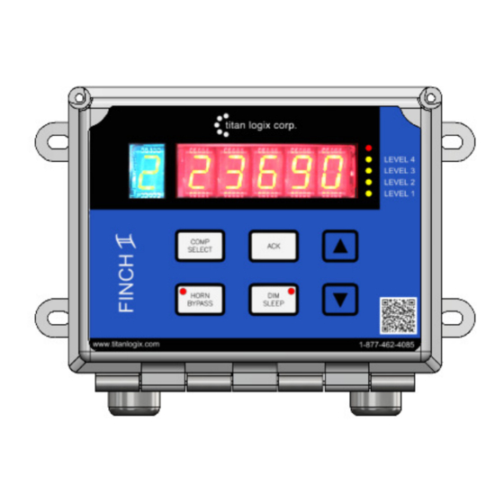
Finch II display is done through the Finch II Utility. See TPM 051 – Finch II Programming Manual for further details. TD100 reported errors or malfunctions are indicated by the Finch II showing “E xxxx”, where “xxxx” is an error code and activates the Fail alarm. - Page 19 RED 5 DIGIT DISPLAY: The 5 red digits can display volume readings, alarm messages, error codes, fill/fall settings, and offset calibration settings. When no TD100 connection is available, the display will show “-----“. RED LED: The red LED at the top right of the display is used to indicate an error state. Currently, this LED is enabled during Spill and Fail alarms and any alarms set to “Not Acknowledgeable”...
- Page 20 OVERVIEW TD100 Installation and Operation Manual % of HH Level LED 100% Level 4 Level 3 Level 2 Level 1 COMPARTMENT (COMP.) SELECT BUTTON: The green digit is used to indicate the currently selected compartment. Each COMP SELECT button press will cycle the display through the available compartments and optional 3 party devices.
-
Page 21: Finch Ii Modes Of Operation
The display has 3 brightness levels max, medium, and low as well as sleep mode. When in sleep mode, the display is turned off and does not respond to any TD100 alarms. This button press will put the display to sleep after the lowest brightness setting. All acknowledgeable alarms must be cleared with the ACK button before entering sleep. - Page 22 When the liquid level reaches the programmed SPILL alarm level, the display flashes “SPILL” and the • last known volume before the Spill alarm. To clear the alarm, fluid must be removed from the tank while the TD100 and Finch II Display are • turned on.
-
Page 23: Finch Ii Relays
The relays have all contacts, Normally Open (NO), Normally Closed (NC) and Common (COM) contacts available for power or signal control. The TD100 generated alarms, or alarms generated by the Finch II display can control these relays for various purposes including overfill prevention. -
Page 24: 5332 Int In-Cab Display
The 5332INT In-Cab display receives a continuous stream of volume information and alarm states from the TD100 over the SV Bus communication line. Volume alarm states and errors are shown on the numeric display. Alarms and errors control relays to signal or operate external devices. Relays can indicate Spill, High-High and system Fail alarms to external devices such as overfill prevention valves, lights, horns and stationary loading controls. -
Page 25: Figure 17 5332Int In-Cab Display
RED 4 DIGIT DISPLAY: The display shows volume readings, alarm messages, error codes, fill/fall settings, and offset calibration settings. When no TD100 connection is available, the display will show “-----“. UNITS OVERLAY: An area where the user can manually write preferred units of operation. -
Page 26: 5332Int In-Cab Modes Of Operation
In this mode the 5332INT display shows the current tank level, as well as any errors received from the TD100 transmitter. The unit will act on any alarms it receives. To enter Monitor Mode the PTO must be on (grounded). -
Page 27: Figure 20 2 Lo Display
OVERVIEW TD100 Installation and Operation Manual button down will change the level by tens of units. The fill level is prevented from exceeding the HH Level. After 5 seconds of inactivity the 5332INT display will revert to the previous display. - Page 28 TD100 Installation and Operation Manual Calibration adjusts the strapping table offset in the TD100 transmitter. The transmitter also ensures that the HH alarm volume level does not exceed the Spill alarm level; the unit will not allow the operator to continue adjusting levels in that direction.
-
Page 29: Installation
TD100 Installation and Operation Manual 4 INSTALLATION NOTE It is recommended that the user updates the TD100 transmitter and the Finch II firmware to the newest version prior to installation. Refer to TPM051 Finch II Programming manual. The latest firmware can be located at. -
Page 30: Figure 22 Td100 System Mount - Side View
Ensure that the vehicle power is turned off before performing any other work. CAUTION Ensure fuses and components are appropriate for the area classification. Figure 22 TD100 System Mount - Side View TPM 057 Version 1.0, May 31, 2018 Page | 26... -
Page 31: Probe Installation
INSTALLATION TD100 Installation and Operation Manual Figure 23 TD100 System Mount - Top View 4.2.1 Probe Installation Care must be taken when installing the probe. The nature of Guided Wave RADAR requires a 4” minimum diameter around the probe to be free of metal. -
Page 32: Figure 24 Probe Location
Alternative fittings must not be longer than 1 ½”. Fittings exceeding 1 ½” in length with an internal diameter of less than 4” interfere with the RADAR signal and prevent the TD100 transmitter from measuring the liquid level or cause false level alarms. -
Page 33: Figure 25 Curved Surface Fitting Mount
INSTALLATION TD100 Installation and Operation Manual 1. Make a hole in the top of the tank where indicated by the manufacturing or installation drawings. 2. Ensure that the top fitting will allow the probe to hang vertically in the tank. If the tank has a curved top a leveling piece may be required. -
Page 34: Figure 26 Top Fitting Location
INSTALLATION TD100 Installation and Operation Manual NOTE No Mounting Hardware Should Extend Beyond 1½” Below the Nut on the Probe. Figure 26 Top Fitting Location 4.2.1.2 Mount the Anchor Cone It is recommended to use the supplied anchor cone. The anchor cone is required to prevent excessive flexing and resulting damage to the probe or tank. -
Page 35: Figure 27 Anchor Cone Location
INSTALLATION TD100 Installation and Operation Manual Figure 27 Anchor Cone Location 1. Locate the probe and transmitter according the recommended guidelines. 2. Install the top collar. 3. Screw the swage fitting into the 1” NPT top fitting. 4. Insert the tube into the swage fitting until it reaches the bottom of the tank. - Page 36 INSTALLATION TD100 Installation and Operation Manual The probe ships with a protective orange cap. Ensure that the top of the probe is covered by the orange plastic cap it is shipped with. This cap must remain in place until the transmitter is mounted to protect from dirt, oil, and physical damage.
-
Page 37: Figure 28 Probe Measurement
INSTALLATION TD100 Installation and Operation Manual Figure 28 Probe Measurement Figure 29 Cutting the Probe TPM 057 Version 1.0, May 31, 2018 Page | 33... -
Page 38: Transmitter Installation
INSTALLATION TD100 Installation and Operation Manual Figure 30 Probe Installation 4.2.2 Transmitter Installation 1. Ensure sufficient clearance between the transmitter and tank top mounted fittings, obstructions or manway. Provide at least 4” of clearance around the transmitter. Consider the installation location for clearance of the large 1 ¾”... -
Page 39: Finch Ii/5332Int Display Installation
Observe all federal, state/provincial and local safety standards and industry recommended practices. This electrical installation refers to the TD100 transmitter and optional equipment. For a complete description of the electrical installation of the Finch II display, refer to TPM010 Finch II Installation and Operation Manual. -
Page 40: Installation Wiring - System
Observe the following instructions during installation: The TD100 transmitter is provided with a 50’ or 75’ cable kit (optional). It is recommended to • use the kit with included sealing fitting for connection to the Finch II display. If the cable kit is not used, a cable assembly is selected that uses a sealing fitting if the transmitter is installed in a hazardous area. -
Page 41: Installation Wiring - Transmitter
INSTALLATION TD100 Installation and Operation Manual 4.3.2 Installation Wiring - Transmitter Figure 32 Transmitter/Finch II Connections Schematic TPM 057 Version 1.0, May 31, 2018 Page | 37... -
Page 42: Installation Wiring - Finch Ii Relays
4.3.3 Installation Wiring - Finch II Relays For additional programming options Refer to Figure 34 and to the Finch II Programming Manual TPM051 manual. Any TD80 references in TPM051 will correlate with TD100 wiring applications for the purposes of this wiring installation. -
Page 43: Installation Wiring - 5332Int In-Cab Display
1. Fused Power wire from the fuse or junction box through a 3A fuse to 5332INT POWER IN (red wire) 2. Ground wire from the fuse or junction box to 5332INT GROUND (black wire) 3. TD100 Power (black wire) to 5332INT GAUGE PWR (red wire) 4. TD100 Ground (white wire) to 5332INT GAUGE GND (black wire) TPM 057 Version 1.0, May 31, 2018... -
Page 44: Installation Wiring - Current Loop Option
GROUND when not connected to a PTO or brake air switch 4.3.5 Installation Wiring - Current Loop Option The 4-20mA current loop option may be used along with any TD100 configuration. This option does not interfere with the Finch II display, lights, horns, RCM, or the MIC 10. -
Page 45: Figure 34 Current Loop Wiring Diagram
INSTALLATION TD100 Installation and Operation Manual Figure 34 Current Loop Wiring Diagram Figure 35 TD100 Transmitter Wiring Schematic TPM 057 Version 1.0, May 31, 2018 Page | 41... -
Page 46: Configuration & Calibration
5 CONFIGURATION & CALIBRATION 5.1 T RANSMITTER The TD100 system must be configured before use. This is done through the Finch II display or the 5332INT In-Cab display, and the SensorLink software. HH and Spill alarms are set by the installer with the SensorLink software (refer to the SensorLink User Manual TPM058). -
Page 47: Finch Ii Display
RANSMITTER PTION The liquid level is detected by the TD100 using a probe and transmitter. This level or depth is converted into a signal of between 4mA and 20mA. A current of 4mA represents the lowest value in the measurement range, or 0% full. The 4-20mA signal represents depth of the liquid, not volume. -
Page 48: Start Up
CONFIGURATION TD100 Installation and Operation Manual Data and Alarm States TD100 SV Bus and Finch II TD100 4-20mA Signal Display Level Output Volume, 0-9999 units Depth, 0 to 100% = 4 to 20mA 10 Second Warm Up 3.8mA 2 LO Indication... - Page 49 1. Inspect installation before power is applied. 2. Turn power on to the TD100 system. During the warm-up cycle, the Finch II display will run tests showing the current software revision number, followed by a display test consisting of all five digits and compartment number(s) showing the values from 0 to 9 and A to F.
-
Page 50: Offset Calibration
4. Refer to the strapping chart to determine the distance between the TD100 reported volume and the metered amount. 5. At the next site, load the tank to approximately 3/4 full. Note the TD100 reported volume. TPM 057 Version 1.0, May 30, 2018... -
Page 51: Method 3: Offset Calibration Using A Measured Level
Spill alarm setting are within the probe top deadband where measurements are unreliable. The Spill alarm is cleared by unloading liquid below the spill alarm level, while the TD100 system is powered on and reporting level through the SV bus and optional 4-20mA transmitter. This is the normal method to silence the Spill alarm. - Page 52 CONFIGURATION TD100 Installation and Operation Manual WARNING Using the Offset Calibration Method will bypass the Spill Alarm and may result in a spill situation. Ensure fluid in the tank has been reduced to a safe level. A Spill alarm may be cleared by starting an Offset Calibration from the Finch II display. Do not change the current offset, cycle the system power and the Spill alarm will be cleared.
-
Page 53: Troubleshooting & Maintenance
TROUBLESHOOTING TD100 Installation and Operation Manual 6 TROUBLESHOOTING & MAINTENANCE For complete system troubleshooting Refer to the 5332INT (TPM059) or Finch II (TPM010) manuals for complete troubleshooting information. 6.1 R EQUIRED OOLS AND QUIPMENT Short length of wire bare at both ends or with alligator clips. - Page 54 TROUBLESHOOTING TD100 Installation and Operation Manual The above error codes may be combined if more than one error code exists at a time (e.g. E26 = E02+E04+E20). ERROR FINCH II 5332INT ERROR CODE DESCRIPTION POSSIBLE SOLUTIONS CODE - possible shorting block has fallen off.
- Page 55 TROUBLESHOOTING TD100 Installation and Operation Manual ERROR FINCH II 5332INT ERROR CODE DESCRIPTION POSSIBLE SOLUTIONS CODE - this may occur after upgrading from old firmware, Loaded old sector 1 settings E705 E0705 power cycle display. from flash - check relay assignments and Fill/Fall alarm settings.
-
Page 56: System Troubleshooting
TROUBLESHOOTING TD100 Installation and Operation Manual 6.3 S YSTEM ROUBLESHOOTING The following troubleshooting items identify some of the most common system wiring and component failures along with suggested troubleshooting and repair steps. Always check there is power to the battery and that power is applied through the wiring to the transmitter and displays. - Page 57 The TD100 transmitter may be Reprogram the transmitter with correct information. incorrectly programmed. Replace the TD100 transmitter with a serviceable unit that has c. The TD100 transmitter may be been programmed with same information as the one it is defective.
- Page 58 Retighten the contamination. connectors and test the system. Spill alarm is on continuously, unable to clear the alarm by unloading while the TD100 is turned on or by entering Calibration mode. DETAILS: REMEDY: WHAT TO DO: a.
- Page 59 TD100 transmitter power may be independent from the Finch II Display power. Power must be cycled to the Finch II Display and TD100 at the same time for offset calibration. c. Finch II Display shows a i. The TD100 transmitter may be Replace the TD100 transmitter with level after flashing “CAL”,...
-
Page 60: Current Loop System (Option)
Most 4-20mA problems are caused by other failures and are only indicated by the output. Ensure that the TD100 system is provided power from a well charged battery or DC power supply, 8VDC to 30VDC. -
Page 61: Repair
4. Measure the 4-20mA loop current and check for the following: a) 0mA indicates a broken wire or defective current loop component b) 3.8mA indicates that the TD100 transmitter is still in the 10 second warm up cycle or did not start normally. -
Page 62: Reference Drawings
DRAWINGS TD100 Installation and Operation Manual 7 REFERENCE DRAWINGS Figure 38 TD100 System Component Location TPM 057 Version 1.0, May 30, 2018 Page | 58... - Page 63 Manufactured by: Manufactured in Canada Head Office 4130-93 Street Edmonton, Alberta Canada T6E 5P5 P 780.462.4085 F 780.450.8369 Toll Free 1.877.462.4085 | TSX-V: TLA Sales Department: Email us at sales@titanlogix.com | Service Department: Email us at support@titanlogix.com Find us online at www.titanlogix.com...
Need help?
Do you have a question about the TD100 and is the answer not in the manual?
Questions and answers