
Related Manuals for Hinowa IIIS Series

Summary of Contents for Hinowa IIIS Series
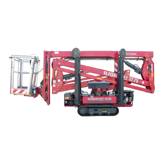
- Page 1 Operation, Safety, Maintenance and service Manual Original Instructions - Keep this manual with the machine at all times. Self-propelled Tracked Platform LIGHTLIFT 17.75 Serie IIIS MULL177520113...
- Page 3 HINOWA LIFT FOREWORD Contact: HINOWA SPA Via Fontana 37054 Nogara ‑ Verona Italy Phone: +39 0442 539100 Fax: +39 0442 539075 E‑mail: hinowa@hinowa.it Original languages of the manufacturer: Italian and English. All other languages are copies of the original instructions.
- Page 4 HINOWA LIFT FOREWORD Manual code Date edition Description of the review May, 2012 Original Issue MULL177520512 • The emergency control key on the ground stop box has been replaced with a selector. • The hand control screws of the ground part pro‑...
-
Page 5: Table Of Contents
SELF‑PROPELLED TRACKED PLATFORM LL1775 HINOWA TABLE OF CONTENTS CHAPTER PRESENTATION ..................Page 07 CHAPTER TECHNICAL INFORMATION ............Page 08 Description of the machine ..............Page 08 2.1.1 Control position ..................Page 08 2.1.2 Machine identification plate ..............Page 11 2.1.3 Overall dimensions of the machine .............Page 12 2.1.4... - Page 6 SELF‑PROPELLED TRACKED PLATFORM LL1775 HINOWA 6.4.1 Preliminary checks before starting work ...........Page 70 6.4.2 Starting the petrol/diesel engine ............Page 71 6.4.3 Starting the electric motor ..............Page 72 6.4.4 Stopping the engine/motor ..............Page 74 6.4.5 Stopping the motor lithium version ............Page 74 6.4.6...
- Page 7 SELF‑PROPELLED TRACKED PLATFORM LL1775 HINOWA 7.15 Checking the condition of the filter cartridge ........Page 128 7.16 Checking that all the plates are present on the machine and intact ....................Page 128 7.17 Checking the operating pressure of the hydraulic system ....Page 129 7.18 Checking tightness of the fastening screws on the pin retainers and the locknuts..................Page 129...
- Page 8 NING REGARDING USE OF THE MACHINE IN STANDARD AND EMERGENCY CONDITIONS. THE EMPLOYER MUST ALSO TRAIN OPERATORS REGARDING ANY NATIONAL STANDARDS THAT ARE IN ADDITION TO THE INSTRUCTIONS CONTAINED IN THIS DOCUMENT. If the manual is damaged or lost, a copy must be requested directly from HINOWA. MULL177520113...
- Page 9 Essential Safety Requisites of the 2006/42/CE Machinery Directive even if a type C Volun‑ tary Technical Standard. According to that stated in EN280 prA2, the HINOWA platform is classified in GROUP B, as the vertical projection of the centre of gravity of the load can be outside of the tilting lines and in TYPE 1 as traversing is only allowed with the platform at rest.
- Page 10 - Via Fontana - 37054 NOGAR A (Verona) - ITALIA - Tel. +39 (0)442 539100 - Telefax +39 (0)442 539075 - E-mail: hinowa@hinowa.it web site: www.hinowa.com - R eg. Impr. C .C .I.A.A. 01996640239 - R .E.A. 210602 - C od. Fisc. e Part. Iva IT 01996640239 - C ap. S oc. € 1.500.000,00 i.v.
-
Page 11: Chapter 1 Presentation
SELF‑PROPELLED TRACKED PLATFORM LL1775 HINOWA 1. PRESENTATION This manual describes the warning signs used to draw the reader’s attention to several parti‑ cularly important warnings. The safety warnings are divided into two main types, which are identified and described below. -
Page 12: Chapter 2 Technical Information
2.1.1 CONTROL POSITION ‑ CONTROL POSITION IN THE BASKET The HINOWA overhead platform has been designed to be controlled by the operator in the basket using a remote control, where all of the machine functional controls are gathered, positioned in the relevant support inside the basket (see photo). A optional pedal button is also present in the basket to allow movement of the aerial part (photo). - Page 13 SELF‑PROPELLED TRACKED PLATFORM LL1775 HINOWA CONTROL POSITION ON THE GROUND: There is a second control position available for the tracked part of the machine. This is not in a fixed position but rather can be located on the ground within a radius of 2.5 m from the basket attachment.
- Page 14 SELF‑PROPELLED TRACKED PLATFORM LL1775 HINOWA PHOTO 1 PHOTO 2 There is a control position available only for scheduled and unscheduled maintenance opera‑ tions, placed near the electrical components compartment on the machine. On the electric board protection there is an auxiliary connector for the connection of the optional second remote control (see photo).
-
Page 15: Machine Identification Plate
SELF‑PROPELLED TRACKED PLATFORM LL1775 HINOWA 2.1.2 MACHINE IDENTIFICATION PLATE The manufacturer plate is placed on the protection of the aerial part hydraulic distributor. The drawing is shown below. MULL177520113... -
Page 16: Overall Dimensions Of The Machine
SELF‑PROPELLED TRACKED PLATFORM LL1775 HINOWA 2.1.3 OVERALL DIMENSIONS OF THE MACHINE Maximum length in travel configuration with basket installed ......4529 mm Track width ......................798/1086 mm Maximum height in travel configuration with foot plates removed ....2000 mm Maximum attachment angleo................20° Maximum stabilisation angle ................12°... -
Page 17: Technical Specifications
SELF‑PROPELLED TRACKED PLATFORM LL1775 HINOWA 2.1.4 TECHNICAL SPECIFICATIONS PLATFORM CAPACITY 230 kg PLATFORM HEIGHT (floor) 14,96 m MAX WORKING HEIGHT 17,06 m STANDARD BASKET DIMENSIONS 1335 x 690 x H1100 mm HORIZONTAL EXTENSION 7,00 m MAX HORIZONTAL OUTREACH 7,50 m ROTATION (non-continuous) 360°... -
Page 18: Petrol Engine Technical Specifications
SELF‑PROPELLED TRACKED PLATFORM LL1775 HINOWA 2.1.4.1 TECHNICAL DATA – PETROL ENGINE Make/Model ................HONDA iGX440 Fuel/Cooling ................PETROL/AIR Power SAEJ1349 ................9,5 Kw (12,7cv) / 3600rpm Max speed ..................3600 rpm Maximum torque ................29,8 Nm/2500 rpm (80/1269/EC) Number of cylinders ................1 Displacement ................440 cm Sound power level at operator’s ear ........88 dB... -
Page 19: Electrical System Technical Specifications Lithium
SELF‑PROPELLED TRACKED PLATFORM LL1775 HINOWA 2.1.4.4 ELECTRICAL SYSTEM TECHNICAL SPECIFICATIONS THERMIC Battery ................55 Ah ‑ 240 A ‑ 12V Alternator petrol engine ..........20 A (3600 rpm) Alternator diesel engine ..........14 A (3000 rpm) Electric motor: ‑ rated voltage..........230 V ‑ frequency ..........50 Hz ‑... -
Page 20: Terminology
SELF‑PROPELLED TRACKED PLATFORM LL1775 HINOWA 2.1.5 TERMINOLOGY To make the contents of this manual easier to understand, the diagram provided below illu‑ strates the terms used to identify the parts of the platform. 19 Extension arm Tracked undercarriage 20 Jib cylinder... -
Page 21: General Safety Standards
SELF‑PROPELLED TRACKED PLATFORM LL1775 HINOWA 2.2 GENERAL SAFETY STANDARDS WARNING The functioning of the MEWPS must be in compliance with international standards of refe‑ rence (see paragraph “NORMATIVE REFERENCES” in the first pages of the manual) and national or regional standards if stricter. - Page 22 SELF‑PROPELLED TRACKED PLATFORM LL1775 HINOWA sis performed are in perfect working condition. IMPORTANTE IMPORTANT USE THE TYPE‑APPROVED AND CERTIFIED SAFETY HARNESSES. BEFORE WORKING AT A HEIGHT, MAKE SURE THAT THE SAFETY HARNESSES ARE COR‑ RECTLY FASTENED AND CONNECTED TO THE ANCHORAGE POINTS ON THE BASKET.
- Page 23 SELF‑PROPELLED TRACKED PLATFORM LL1775 HINOWA • Cleaning the machine Always park the machine as shown in the figure in point 2.1.5. WARNING When washing the machine, the ignition block must be disengaged, the key removed and the emergency stop button pressed.
- Page 24 SELF‑PROPELLED TRACKED PLATFORM LL1775 HINOWA IMPORTANTE IMPORTANT Only use dry detergents, in accordance with the manufacturer’s instructions. Never remove covers, guards and the like. ‑ Clean the electrical system using a dry, non‑metallic brush and low pressure air. • After cleaning Dry the machine carefully before starting it again (for example using compressed air).
-
Page 25: Safety Warnings
Make sure that any new components on the machine are provided with the correct safety signs. 2.3.2 NOISE AND VIBRATIONS The HINOWA platforms with electric motor have been tested according to the parameters of European directive 2000/14 EC, with the guaranteed sound power level measurement shown on the machine’s EC declaration of conformity. -
Page 26: Pictograms Positioned On The Machine
SELF‑PROPELLED TRACKED PLATFORM LL1775 HINOWA 2.3.3 PICTOGRAMS POSITIONED ON THE MACHINE Here we report the positions of the various boards with pictograms on the machine. MULL177520113... - Page 27 SELF‑PROPELLED TRACKED PLATFORM LL1775 HINOWA MULL177520113...
- Page 28 SELF‑PROPELLED TRACKED PLATFORM LL1775 HINOWA POS. CODE Q.ty POS. CODE Q.ty 6555500 6041600 6555600 6043900 6555700 6056300 6555800 6164600 6041200 6232100 6506700 7240300 6068700 7198800 6924300 6040400 07034200 6040500 7199000 6040900 1608710001 6041300 1608710002 6041000 7199100 6044000 06254800 6086600 1704277...
- Page 29 SELF‑PROPELLED TRACKED PLATFORM LL1775 HINOWA LANGUAGE STICKERS POS. CODE Q.ty POS. CODE Q.ty 171986IT 171986DE 6555300 6562800 6561200 6561200 6448200 6462900 6448100 6462300 07319100 073191DE 171986GB 171986ES 6562600 6561200 6562900 6042400 6561200 6257300 6463000 6462700 6462400 6462100 073191ES 073191GB 171986NL...
- Page 30 SELF‑PROPELLED TRACKED PLATFORM LL1775 HINOWA MULL177520113...
- Page 31 SELF‑PROPELLED TRACKED PLATFORM LL1775 HINOWA MULL177520113...
- Page 32 SELF‑PROPELLED TRACKED PLATFORM LL1775 HINOWA Code 06931100 07206100 06506700 06506400 0693100 06922200 06520600 07243100 07264700 LANGUAGE STICKERS Code Code 169249IT 169249GB 06804900 06924800 06561200 06561200 06448100 06042400 06448200 06257300 06555300 06462100 06909000 06462700 06908900 06562600 06909100 06924600 06924500 06924700 Code...
- Page 33 SELF‑PROPELLED TRACKED PLATFORM LL1775 HINOWA Code Code 169249ES 169249NL 06940800 06940900 06561200 06561200 06462400 06462500 06463000 06463100 06562900 06563000 06940400 06940500 06939600 06939700 06940000 06940100 Code Code 169249PT 169249SW 06941000 07259500 06561200 06561200 06462600 07137400 06463200 07137500 06563100 07137300 06940600...
- Page 34 SELF‑PROPELLED TRACKED PLATFORM LL1775 HINOWA Code Name Description Identikit WARNING KEEP 06040300 SAFE DISTANCE SENSE OF MOVING DEFINED AS THE 06040500 UNDERCARRIAGE DIRECTION FORWARD CRUSHING HAZARD 06040800 PERSON 06040800 OBLIGATION TO READ THE MANUAL 06040900 BEFORE USE OF MACHINE INDICATES CORRECT...
- Page 35 SELF‑PROPELLED TRACKED PLATFORM LL1775 HINOWA Code Name Description Identikit INDICATES CORRECT 06044000 LIFTING POINT LIFTING POINTS FOR LIFT THE MACHINE DANGER HIGHT 06056300 TEMPERATURE 06060000 ENGINE OIL LEVEL DEVICE THAT ALLOWS TO EXCLUDE THE EMERGENCY DEVI‑ SAFETY OF THE 06085900...
- Page 36 SELF‑PROPELLED TRACKED PLATFORM LL1775 HINOWA Code Name Description Identikit HYDRAULIC OIL 06165000 LEVEL FORBIDDEN LIFTING 1701499 POINT 1701499 DO NOT WASH 06506700 WITH WATER 06560500 GROUNDING QUICK INSTRUCTIONS HAND PUMP 06998800 FOR USING THE EMER‑ LEGEND GENCY HAND PUMP USING SAFETY HAR‑...
- Page 37 SELF‑PROPELLED TRACKED PLATFORM LL1775 HINOWA Code Name Description Identikit USE PPE AT ALL 06040400 TIMES WHEN WORKING COMPLY WITH THE GREASING INTER‑ 06136900 VALS AT THE SPECIFIED POINTS 06164600 AIR FILTER HYDRAULIC OIL 06164700 FILTER ENGINE REFRIGE‑ 06214200 RANT LEVEL POSITION OF EMER‑...
- Page 38 SELF‑PROPELLED TRACKED PLATFORM LL1775 HINOWA Code Name Description Identikit DANGER BATTERY PACK WARNING! Li-ion WARNINGS Opening and handling the battery pack are dangerous operations. Not respecting this prohibition causes the guarantee decay. DON’T OPEN THE BATTERY PACK. - Only qualified FAAM Group Service is authorized to handle and replace the pack and the fuse.
- Page 39 SELF‑PROPELLED TRACKED PLATFORM LL1775 HINOWA Code Name Description Identikit It is compulsory to wear GLASSES REQUIRED protective glasses. HEAT RESISTANT GLO‑ 06924800 VES: Work requiring con‑ tact with high temperatu‑ re components, in parti‑ cular during maintenance GLOVES REQUIRED operations.
- Page 40 SELF‑PROPELLED TRACKED PLATFORM LL1775 HINOWA MULL177520113...
-
Page 41: Chapter 3 Safety Devices
SELF‑PROPELLED TRACKED PLATFORM LL1775 HINOWA 3 SAFETY DEVICES The information given below concerning the safety devices are provided to the user in order to allow him/her to understand the machine behaviour and possible work sequences; moreo‑ ver, in this way it is possible to identify any breakdowns with greater precision and to sup‑... -
Page 42: Battery Cutout Switch
SELF‑PROPELLED TRACKED PLATFORM LL1775 HINOWA 3.1 BATTERY CUTOUT SWITCH THERMIC MOTOR LITHIUM MOTOR This device, located on the left side of the electrical components compartment, is used to iso‑ late the machine’s electrical circuit, stopping any movements. It is well‑visible and easily accessed without using tools. -
Page 43: Cylinder Stop Valves
SELF‑PROPELLED TRACKED PLATFORM LL1775 HINOWA 3.3 CYLINDER STOP VALVES The stabiliser cylinders have a double stop valve which in case of system breakdown or hose breakage stops the cylinder preventing dangerous platform instability situations. All cylinders that move the aerial part of the platform structure are fitted with a stop valve which in case of system breakdown or hose breakage stops the cylinder preventing the basket from falling due to gravity. -
Page 44: Stabiliser Position Microswitches
SELF‑PROPELLED TRACKED PLATFORM LL1775 HINOWA 3.5 STABILISER POSITION MICROSWITCHES, STANDARD VERSION The position of the stabilisers and their contact with the ground are detected by 4 microswit‑ ches positioned near the stabiliser cylinder rod fastening pin. The microswitches fixed to the stabiliser must be released when the stabiliser rests on the ground. -
Page 45: Basket Load Sensor
SELF‑PROPELLED TRACKED PLATFORM LL1775 HINOWA 3.7 BASKET LOAD SENSOR The load sensor on the basket is made up of a basket sup‑ port with two shafts that only allow the vertical move‑ ment of the basket. The basket support is supplied by the load cell itself. -
Page 46: Control Protection
SELF‑PROPELLED TRACKED PLATFORM LL1775 HINOWA 3.8 CONTROL PROTECTION A protection structure is provided to protect the remote control against the accidental fall of objects from above and involuntary activation by the operator. Always make sure that this protection structure is intact before using the machine. -
Page 47: Pin Locking Bolts And Nuts
HINOWA 3.10 PIN LOCKING BOLTS AND NUTS All the pins used on the HINOWA platform were treated against wear and are fitted with flanges (1) to prevent them from rotating inside their seat. Some pins have bolts to stop rota‑... -
Page 48: Chapter 4 Instruments And Controls
SELF‑PROPELLED TRACKED PLATFORM LL1775 HINOWA 4 INSTRUMENTS AND CONTROLS Below is a description of all the controls and indicators present on the platform; each device has a sticker that briefly describes its function applied nearby, often containing symbols that are used to ensure quick and clear understanding. Before using the platform, the following descriptions must be read in order to gain in‑depth knowledge of the functions of each devi‑... -
Page 49: Display
SELF‑PROPELLED TRACKED PLATFORM LL1775 HINOWA 4.1.1 DISPLAY The display is used to view the status of the machine and the operating information neces‑ sary or useful for the operator. When the machine’s main control board is powered via the engine key, the information to be shown on the display is sent to the remote control. - Page 50 SELF‑PROPELLED TRACKED PLATFORM LL1775 HINOWA POSITION 3: Position 3 displays the engine/motor selection and the engine status. Petrol/diesel engine Electric motor An X on the icon indicates that the engine/motor is off, no X indicates that it is on. POSITION 4:...
- Page 51 SELF‑PROPELLED TRACKED PLATFORM LL1775 HINOWA When the load sensor measures a load exceeding the allowed work load ‑ 230 kg ‑ the main screen disappears for three seconds, replaced by the overload error display, the audible war‑ ning is activated, then the overload icon appears in position 5 in place of the icon enabling the overhead movements.
- Page 52 SELF‑PROPELLED TRACKED PLATFORM LL1775 HINOWA POSITION 7: Position 7 is used for functional signals: Emergency STOP pressed Signals that one of the emergency stop buttons on the machine has not been released. BATTERY VOLTAGE BELOW MINIMUM LIMIT. Indicates that the battery charge level is below the minimum limit allowed. If this message appears, it is advisable to recharge the battery, either by keeping the diesel or petrol engine on, or by connecting to the network.
-
Page 53: Joysticks
SELF‑PROPELLED TRACKED PLATFORM LL1775 HINOWA The angular position control does not work correctly The machine has a CANBUS line connection fault. A faulty or incorrect electronic board (card) has been installed, or alter‑ natively an incorrect software version has been loaded. - Page 54 SELF‑PROPELLED TRACKED PLATFORM LL1775 HINOWA FORWARDS 07071000B BACKWARDS MOVEMENT CONTROLLED JOYSTICK AERIAL MOVEMENTS ENABLED JOYSTICK SHIFTING DIRECTION FORWARDS LEFT TRACK FORWARDS BACKWARDS LEFT TRACK BACKWARDS FORWARDS 1st‑2nd ARM UP BACKWARDS 1st‑2nd ARM DOWN FORWARDS 3rd ARM UP BACKWARDS 3rd ARM DOWN...
-
Page 55: Push Buttons
SELF‑PROPELLED TRACKED PLATFORM LL1775 HINOWA FORWARDS JIB OPENING BACKWARDS JIB FOLDING FORWARDS ANTICLOCKWISE ROTATION BACKWARDS CLOCKWISE ROTATION FORWARDS RIGHT TRACK FORWARDS BACKWARDS RIGHT TRACK BACKWARDS CLOSE BASKET LEVELLING OPEN BASKET LEVELLING 4.1.3 PUSH BUTTONS The buttons have a dual function: they can be used to select machine functions or as numeri‑... - Page 56 SELF‑PROPELLED TRACKED PLATFORM LL1775 HINOWA BUTTON 2: Enters the menu for the manual movements of the individual stabilisers. BUTTONS 3‑9: Used to extend and narrow the tracked undercarriage. BUTTON 4 Used to enable control of the emergency descent from the basket. Confirmation that the ope‑...
- Page 57 SELF‑PROPELLED TRACKED PLATFORM LL1775 HINOWA BUTTON 5: Used to select the travel speed and the engine/motor speed. There are three speeds available: • SLOW: engine at 1,500 rpm for the operation of the aerial part, at 2,200 rpm for the operation of the carriage.
- Page 58 SELF‑PROPELLED TRACKED PLATFORM LL1775 HINOWA BUTTON 10 (ONLY PETROL VERSION): Allows the preheating of the petrol engine. One pressure on the button sets the engine at 2200 rpm for 20 seconds, in order to heat the engine and improve the initial phases of use.
-
Page 59: Footswitch
SELF‑PROPELLED TRACKED PLATFORM LL1775 HINOWA 4.2 FOOTSWITCH (OPTIONAL) Inside of the basket is fitted a footswitch device that must be pushed to allow the movement of the machine from the basket. If you try to move the machine without the footswitch pushed the movement will be prohibited and a message on the display will appear infor‑... -
Page 60: Chapter 5 Emergency Devices
SELF‑PROPELLED TRACKED PLATFORM LL1775 HINOWA 5 EMERGENCY DEVICES The following information concerning the emergency devices is provided to help understand the behaviour of the machine and the possible work sequences; moreover, the devices can thus be identified more clearly and quicker action can be taken if emergencies occur. -
Page 61: Hand Pump
SELF‑PROPELLED TRACKED PLATFORM LL1775 HINOWA 5.2 HAND PUMP The hand pump (2) is used to pressurise oil for emergency movements made necessary by any breakdown of the main hydraulic system. The hand pump has a manual switch (1) used to select whether to control the two left stabili‑... - Page 62 The key used to activate the safety device bypass is lead‑sealed on the side of the electrical components compartment near the battery. Force the lead‑sealing to remove it. After using the safety device bypass a HINOWA after‑ sales centre must be contacted in order to verify the causes that determined the need to use the safety device bypass and to lead‑seal the key.
-
Page 63: Emergency Position Controls
SELF‑PROPELLED TRACKED PLATFORM LL1775 HINOWA 5.5 EMERGENCY POSITION CONTROLS ‑ SELECTION PANEL, EMERGENCY STOP AND STARTING ELECTRIC MOTOR ENGINE AERIAL PART START START MOVEMENTS ENABLED LIGHT AERIAL PART MOVEMENTS ENABLED LIGHT THERMIC MOTOR LITHIUM MOTOR This panel houses the following controls: ‑... - Page 64 To do this, proceed as follows: ‑ If not already in your possession procure the appropriate service kit from ground in an authorized Hinowa centre. ‑ With the machine off (key on OFF position) connect the service cable for ground remote...
- Page 65 SELF‑PROPELLED TRACKED PLATFORM LL1775 HINOWA ‑ AERIAL PART HYDRAULIC DISTRIBUTOR The hydraulic distributor is fitted with levers and buttons for the selection of the required movement, its direction and speed. The structure is moved by using the levers after holding the key in position.
- Page 66 SELF‑PROPELLED TRACKED PLATFORM LL1775 HINOWA Moving lever 5 downwards: basket rotates clockwise Basket rotation control Moving lever 5 upwards: basket rotates anticlockwise Moving lever 6 downwards: basket opens Basket levelling control Moving lever 6 upwards: basket closes Moving lever 7 upwards:...
- Page 67 SELF‑PROPELLED TRACKED PLATFORM LL1775 HINOWA Ref. Description Lever/Movement obtained Pictogram near the control Moving lever 1 downwards: rear L stabiliser down Rear left stabiliser control Moving lever 1 upwards: rear L stabiliser up Moving lever 2 downwards: Front left stabiliser...
-
Page 68: Chapter 6 Using The Machine
SELF‑PROPELLED TRACKED PLATFORM LL1775 HINOWA 6. USING THE MACHINE 6.1 SAFETY STANDARDS TO ADOPT BEFORE USING THE PLATFORM 6.1.1 RISK OF ELECTROCUTION If the machine must be used near electric power lines, the user must remain at a suitable distance from the latter. The table below supplies the values relating to the minimum distan‑... -
Page 69: Danger Due To Atmospheric Conditions
SELF‑PROPELLED TRACKED PLATFORM LL1775 HINOWA 6.1.2 DANGER DUE TO ATMOSPHERIC CONDITIONS DO NOT WORK IN UNFAVOURABLE ATMOSPHERIC CONDITIONS Do not work in the presence of storms, snow, fog or wind exceeding 12 m/s. Do not operate the machine when the ambient temperature drops below–10°C or exceeds +40°C. -
Page 70: Procedures For Correct Use
SELF‑PROPELLED TRACKED PLATFORM LL1775 HINOWA 6.2 PROCEDURES FOR CORRECT USE Below find the procedures for use of the platform as declared by the Constructor. Any use different to that stated below, unless authorised in writing by the Constructor. is prohibited. - Page 71 SELF‑PROPELLED TRACKED PLATFORM LL1775 HINOWA working height. • Always operate the controls slowly and smoothly, without reversing movements suddenly. • Remember that the basket must only be loaded and unloaded FROM THE GROUND. • Do not use the machine at temperatures below ‑20°C and above 40°C. Do not recharge the batteries at temperatures below 0°C and above 40°C.
-
Page 72: Working Area
SELF‑PROPELLED TRACKED PLATFORM LL1775 HINOWA 6.3 WORK AREA 360° 5 C 1 0 , 1 0 , Light Lift LL1775 5 0 , 5 A 0 , 5 0 , MAX RATED WORKING LOAD: 230 KG 5 0 , 5 A 0 ,... -
Page 73: Using The Elevating Work Platform (Mewp)
IMPORTANTE IMPORTANT The HINOWA elevating work platforms are suitable for overhead jobs that are performed by an operator from inside the basket. The platform must be used exclusively by skilled person‑ nel who are aware of the position and functions of all controls, instruments, indicators, war‑... -
Page 74: Preliminary Checks Before Starting Work
SELF‑PROPELLED TRACKED PLATFORM LL1775 HINOWA ‑ When climbing into the basket, fasten the safety harnesses immediately to the appro‑ priate fixing points before carrying out any operations. Remember that the safety har‑ nesses must be checked and TESTED PERIODICALLY. ‑... -
Page 75: Starting The Petrol/Diesel Engine
SELF‑PROPELLED TRACKED PLATFORM LL1775 HINOWA 6.4.2 STARTING THE PETROL/DIESEL ENGINE Before starting the engine it is necessary to: ‑ Become familiar with all the procedures described in the USER AND OPERATION MANUAL of the machine and of the engine, and to know the meaning of the safety labels;... -
Page 76: Starting The Electric Motor
SELF‑PROPELLED TRACKED PLATFORM LL1775 HINOWA ment at the necessary speed. See paragraph concerning the functions of the remote control before using this option. THE ENGINE MUST BE STARTED WITH ALL THE CONTROL BUTTONS AND JOY‑ STICKS IN NEUTRAL POSITION. Always make sure there are no foreign objects (e.g. branches) that may accidentally operate a control, as the platform may move suddenly out of the operator’s control and cause serious... - Page 77 SELF‑PROPELLED TRACKED PLATFORM LL1775 HINOWA ‑ Make sure that all the emergency STOP buttons are released; this condition can be checked on the remote control display, where no icon should appear in position 7. If the operator attempts to start the machine with the emergency stop button still pres‑...
-
Page 78: Stopping The Engine/Motor
SELF‑PROPELLED TRACKED PLATFORM LL1775 HINOWA 6.4.4 STOPPING THE ENGINE/MOTOR To stop the engine, press again button 11 on the remote control; it allows the engine to be switched off or on depending on its status. To stop the electric motor, press button 12; it allows the electric motor to be switched off or on depending on its status. -
Page 79: Travel
HINOWA 6.4.6 TRAVEL The HINOWA machine is a self‑propelled machine able to easily move on any type of ground, over steep slopes (up to 15°) and, considering the small dimensions, to enter narrow openings. One condition for travel is that the four stabilisers are lifted from the ground and the machine is in the transport or stabilisation configuration. - Page 80 SELF‑PROPELLED TRACKED PLATFORM LL1775 HINOWA RAVEL PROCEDURE Before travelling, proceed as follows: ‑ Check that all instructions previously given in this chapter have been complied with; ‑ Make sure that the ground is compact and can support the weight of the machine;...
- Page 81 SELF‑PROPELLED TRACKED PLATFORM LL1775 HINOWA PERICOLO DANGER The machine is equipped with an automatic system of inclination sensing during transla‑ tion, the possible translation speeds are adjusted according to the weight in basket, undercarriage closed or opened, position of JIB and inclination of the ground.
-
Page 82: Jib Arm Movement For Travel
SELF‑PROPELLED TRACKED PLATFORM LL1775 HINOWA 6.4.7 JIB ARM MOVEMENT FOR TRAVEL To take on slopes from 10° to 15° in a longitudinal direction during travel, the jib arm can be raised. ATTENZIONE WARNING PERFORM THIS OPERATION ONLY WHEN REALLY NECESSARY. IN ALL OTHER SITUATIONS, TRAVEL WITH THE MACHINE CLOSED AND ALIGNED. - Page 83 SELF‑PROPELLED TRACKED PLATFORM LL1775 HINOWA After the conditions described above have been checked, make sure there are no obstacles in the working area of the jib arm, and proceed as follows: ‑ Use joystick 6 to move the jib arm. If another joystick is used, an error message will be shown on the display: ‑...
-
Page 84: Parking The Machine On A Slope Or On Uneven Ground
SELF‑PROPELLED TRACKED PLATFORM LL1775 HINOWA 6.4.8 PARKING THE MACHINE ON A SLOPE OR ON UNEVEN GROUND When parking the machine on a slope or uneven ground with the stabilisers closed, make sure that the carriage is in the open position and block the tracks using chocks to prevent the machine from moving. - Page 85 SELF‑PROPELLED TRACKED PLATFORM LL1775 HINOWA The complete closure and alignment is displayed by the arrows on the machine (SEE PHOTO) and the display of the icon in position 6 on the remote control. ‑ Stabilisation can be carried out from the control position in the basket or on the ground.
- Page 86 SELF‑PROPELLED TRACKED PLATFORM LL1775 HINOWA ‑ Stabilisation will be completed when the machine is in horizontal position with toleran‑ ce of 1° and lifted at least 5 cm from the ground. Correct stabilisation will be confirmed by the icon in position 5 on the display.
- Page 87 SELF‑PROPELLED TRACKED PLATFORM LL1775 HINOWA bubble it contains is completely inside the green area (see photo below) the machine is in conditions that allow operation. Please note that stabilize the machine on slopes greater than allowable limits (see technical data of the machine) does not permit correct stabilization and is a serious danger for users.
-
Page 88: Automatic Lowering And Raising Of The Stabilisers
DO NOT REST THE STABILISERS ON VERTICAL OR INCLINED SURFACES. 6.4.10 AUTOMATIC LOWERING AND RAISING OF THE STABILISERS HINOWA elevating platform is fitted with an innovative automatic levelling procedure that acts on the stabilisers and uses the electronic spirit level provided on the main control board. - Page 89 After the end of the procedure, always control that the spirit level is in the green zone. If this does not occur contact HINOWA after sales service. If during lowering one of the stabilisers does not touch the ground, the machine will conti‑...
-
Page 90: Track Gauge Extension
SELF‑PROPELLED TRACKED PLATFORM LL1775 HINOWA The end of the automatic stabiliser raising cycle is shown on a screen for a few seconds. If this screen is not shown, the automatic stabiliser raising procedure can still be considered completed once all the four stabilisers have been completely retracted and consequently the relevant cylinders are at the end of their stroke. -
Page 91: Moving The Basket
SELF‑PROPELLED TRACKED PLATFORM LL1775 HINOWA 6.4.12 MOVING THE BASKET Once the machine has been stabilised correctly (check the icon in pos. 5), the basket can be moved. It is prohibited to load material of any type into the basket if the machine is not stabi‑... - Page 92 SELF‑PROPELLED TRACKED PLATFORM LL1775 HINOWA PROCEDURE FOR ROUTINE MOVEMENT OF THE AERIAL PART • Before moving the aerial part, make sure that: ‑ all instructions provided in this chapter have been complied with; ‑ there are no obstacles in the work area;...
- Page 93 SELF‑PROPELLED TRACKED PLATFORM LL1775 HINOWA OVERLOAD ALARM If during the basket loading phases the max allowable load is exceeded based on the position of the jib arm, all movements of the aerial part will be disabled and an error message will be shown on the display, first on the entire screen and then in position 5.
- Page 94 SELF‑PROPELLED TRACKED PLATFORM LL1775 HINOWA ROTATION WITH 1ST‑2ND ARM FOLDED AND 1ST‑2ND ARM DESCENT ON THE THERMIC/LITHIUM ENGINE If the turret is rotated with the first or second arm folded or nearly folded, there is the risk of the first arm hitting against the engine. For this reason, free rotation areas and limited rota‑...
-
Page 95: Manually Levelling The Basket
HINOWA 6.4.13 MANUAL LEVELLING OF THE BASKET The HINOWA elevating work platform is provided with an automatic basket levelling devi‑ ce that was designed so that the basket floor is always parallel to the ground independently of the movements of the arms. -
Page 96: Emergency Operations On The Aerial Part
SELF‑PROPELLED TRACKED PLATFORM LL1775 HINOWA 6.5 EMERGENCY OPERATIONS FOR THE AERIAL PART The machine was designed considering possible emergency situations such as mechanical and electrical breakdowns, sudden operator illness etc. In all of these cases the machine can be operated both from the basket and from the ground so as to bring it back to the transport configuration or however in such a way as to rescue the occupant/occupants from the basket. -
Page 97: Operating The Machine From The Emergency Control Position On The Ground If The Operator Is Taken Ill
SELF‑PROPELLED TRACKED PLATFORM LL1775 HINOWA 6.5.2 OPERATING THE MACHINE FROM THE EMERGENCY CONTROL POSITION ON THE GROUND IF THE OPERATOR IS TAKEN ILL This function is only used if the operator in the basket becomes suddenly ill and unable to perform ordinary movements and the emergency descent of the basket. -
Page 98: Emergency Descent In The Case Where The Stabilisers Are Accidentally Retracted
SELF‑PROPELLED TRACKED PLATFORM LL1775 HINOWA 6.5.3 EMERGENCY DESCENT IN THE CASE WHERE THE STABILISERS ARE ACCI‑ DENTALLY RETRACTED While it is recommended to follow the instructions provided in the paragraph on stabilising the machine, for various reasons one of the stabilisers may lose contact with the ground, thus changing the angle of the machine or causing a foot plate to lift from the ground. - Page 99 SELF‑PROPELLED TRACKED PLATFORM LL1775 HINOWA The display on the remote control shows the safety device BYPASS icon. Control the machine with the remote control ONLY carrying out operations that allow the machine to be closed: first/second arm folding, extension arm in, jib arm folding. The third arm can be rotated and lowered only with the extension arm completely retracted.
-
Page 100: Emergency Descent Controlled From The Ground Using The Hand Pump In The Event Of Faults On All Energy Supply Systems
SELF‑PROPELLED TRACKED PLATFORM LL1775 HINOWA 6.5.4 EMERGENCY DESCENT CONTROLLED FROM THE GROUND USING THE HAND PUMP IN THE EVENT OF FAULTS ON ALL ENERGY SUPPLY SYSTEMS This emergency descent function is only used if the electrical system and motors break down, meaning one of the previous emergency operations cannot be performed. - Page 101 SELF‑PROPELLED TRACKED PLATFORM LL1775 HINOWA ‑ Use the levers and/or buttons corresponding to the ON‑OFF coils ISTRIBUTOR PROTECTION accessible from the bottom of the distributor protection so as to enable the required movement, following the instructions on the sticker positioned near the controls, and at the same time operate the hand pump to obtain the movement.
-
Page 102: Emergency Operations On The Carriage: Moving The Platform Stabilisers Using The Hand Pump To Allow The Machine To Be Transported
SELF‑PROPELLED TRACKED PLATFORM LL1775 HINOWA 6.5.5 EMERGENCY OPERATIONS ON THE CARRIAGE: MOVING THE PLATFORM STABILISERS USING THE HAND PUMP TO ALLOW THE MACHINE TO BE TRAN‑ SPORTED HE HYDRAULIC HAND PUMP CAN BE USED TO MOVE THE STABILISERS AND SET THE MACHINE IN... -
Page 103: Emergency Operation Of The Undercarriage In The Event Of Movements Of The Aerial Part
SELF‑PROPELLED TRACKED PLATFORM LL1775 HINOWA 6.5.6 EMERGENCY OPERATION OF THE UNDERCARRIAGE IN THE EVENT OF MOVEMENTS OF THE AERIAL PART HE MANOEUVRE DESCRIBED BELOW MUST BE CARRIED OUT ONLY AND EXCLUSIVELY WITH THE MACHINE CLOSED During transport, the aerial part of the machine may turn, con‑... - Page 104 SELF‑PROPELLED TRACKED PLATFORM LL1775 HINOWA Moving the undercarriage with the machine not aligned: PERATION ALLOWED ONLY TO REACH THE CONDITIONS NECESSARY TO PEROFRM THE PROCEDURE ). A DESCRIBED UNDER POINT A NY OTHER USE IS PROHIBITED ‑ Open the electrical components compartment.
-
Page 105: Electrical Disconnection Of The Remote Control
SELF‑PROPELLED TRACKED PLATFORM LL1775 HINOWA 6.6 ELECTRICAL DISCONNECTION OF THE REMOTE CONTROL The electrical disconnection/connection of the remote control MUST be carried out exclu‑ sively with the motor key in position OFF and with the mains power disconnected. • Disconnect the cable from the remote control using the corresponding screw connection. -
Page 106: Recharging The Battery
SELF‑PROPELLED TRACKED PLATFORM LL1775 HINOWA 6.7 RECHARGING THE BATTERY To check the battery charge, always use the special indicator shown on the display on the remote control. The batteries can be recharged even when using the machine (obviously the recharging times in this case will be longer). - Page 107 SELF‑PROPELLED TRACKED PLATFORM LL1775 HINOWA the following essential precautions should be observed: • Carefully read the installation instructions contained in this manual. For future reference, keep the manual in a safe place. • Do not place the battery charger near sources of heat.
- Page 108 SELF‑PROPELLED TRACKED PLATFORM LL1775 HINOWA LED Indicator TECHNICAL SPECIFICATIONS T=25°C unless otherwise specified. Value and/or Description Symbol Test conditions Unit Range Single‑phase power supply voltage ‑ 230 ± 10% Veff Frequency ‑ 50 ÷ 60 If max P = P max...
- Page 109 SELF‑PROPELLED TRACKED PLATFORM LL1775 HINOWA ATTENZIONE WARNING Before use, carefully read the instruction booklet. Make sure that the charge curve selected is suitable for the type of battery being rechar‑ ged. MULL177520113...
-
Page 110: Main Intended Uses Of The Platform
SELF‑PROPELLED TRACKED PLATFORM LL1775 HINOWA 6.8 MAIN INTENDED USES OF THE PLATFORM Below are the specific warnings for the most frequent uses of the machine. The information provided must be considered as an addition to and not a replacement for the contents of the User and Operation manual. -
Page 111: Repair And Maintenance Of Roofing And Gutters
SELF‑PROPELLED TRACKED PLATFORM LL1775 HINOWA 6.8.4 REPAIR AND MAINTENANCE OF ROOFING AND GUTTERS Remember that it is prohibited to use the platform for the transport of material at a height even if this is within the capacity limits specified by the manufacturer; the MEWP is not a lif‑... -
Page 112: Chapter 7 Maintenance
GREASE FOR TRANSMISSION BRAND ENGINE OIL TURNTABLE AND TENSIONER PAKELO SAE 10W30 API CH EP 150 AGIP BLASIA 150 MUEP 1 SPARTAN ESSO BEACON 2 EP 150 To top up or replace the hydraulic oil ONLY use HINOWA oil. MULL177520113... - Page 113 SELF‑PROPELLED TRACKED PLATFORM LL1775 HINOWA HYDRAULIC EP EXTRA HYDRAULIC ISO 68 V.I.180 EP EXTRA / SHELL ISO 46 V.I.160 TELLUS S3V HYDRAULIC / SHELL 68 V.I.180 EP EXTRA TELLUS S3V -5°C/+50°C ISO 32 V.I.160 HYDRAULIC 46 V.I.160 / SHELL EP EXTRA -9°C/+40°C...
-
Page 114: Greasing Points
SELF‑PROPELLED TRACKED PLATFORM LL1775 HINOWA 7.3 GREASING POINTS 0 , 5 0 , 5 0 , 5 0 , 5 0 , 5 0 , 5 M= ENGINE OIL M=OLIO MOTORE T = TRANSMISSION OIL T=OLIO TRASMISSIONE I = HYDRAULIC OIL... -
Page 115: Greasing The Telescopic Arm
SELF‑PROPELLED TRACKED PLATFORM LL1775 HINOWA 7.4 GREASING THE TELESCOPIC ARM Use a brush to apply grease onto the telescopic exten‑ sion arms. 7.5 SAFETY INSTRUCTIONS FOR MAINTENANCE OPERATIONS • Spare parts must correspond to the technical provisions established by the Constructor. -
Page 116: Operating The Machine From The Second Control Position On The Ground Using The Optional Second Remote Control During Maintenance
SELF‑PROPELLED TRACKED PLATFORM LL1775 HINOWA • Fluid that leaks under pressure may penetrate the skin. Always discharge pressure befo‑ re removing the hydraulic hoses and tighten connections correctly before pressurising. Keep hands and body away from small holes and nozzles where high‑pressure liquids may be released. -
Page 117: Periodic Maintenance Intervals
SELF‑PROPELLED TRACKED PLATFORM LL1775 HINOWA 7.7 PERIODICAL MAINTENANCE INTERVALS HONDA PETROL ENGINE INTERVAL (HOURS) BEFORE PART INTERVENTION AS NEEDED STARTING 500 1000 2000 • CHECK, CLEAN DRY AIR FILTER • CHANGE • • CHECK LEVEL ENGINE OIL • • CHANGE •... - Page 118 SELF‑PROPELLED TRACKED PLATFORM LL1775 HINOWA HATZ DIESEL ENGINE INTERVAL (HOURS) BEFORE PART INTERVENTION AS NEEDED STARTING 500 1000 2000 • CHECK, CLEAN DRY AIR FILTER • CHANGE • • CHECK LEVEL ENGINE OIL • • CHANGE • CLEAN ENGINE OIL FILTER •...
-
Page 119: Electric Motor
SELF‑PROPELLED TRACKED PLATFORM LL1775 HINOWA www.honda‑engines‑eu.com / www.hatz‑diesel.com # Anyway every year. If the tightening is not correct replace the nuts with two new with the same specifications and restore the connection without using oil or grease. ELECTRIC MOTOR The electric motor is located inside of the carriage distributor support cover. -
Page 120: Inspection And Maintenance
HINOWA 7.9 INSPECTION AND MAINTENANCE All HINOWA aerial platforms must be inspected, tested and serviced according to the fol‑ lowing instructions. See the user and operation manual for the complete list of recommen‑ ded inspection intervals and the correct checking and servicing procedures. - Page 121 SELF‑PROPELLED TRACKED PLATFORM LL1775 HINOWA Hydraulic oil filters for cracks and leaks, pieces of metal on the filter that may cause pump, motor or cylinder malfunction; rubber particles on the filter that may indicate deterioration of hoses, o‑rings or other rubber components.
-
Page 122: General Periodic Checks
After the first 2000 hours of operation, have a general check run on the machine, at a certi‑ fied HINOWA service centre, where the general condition of the machine will be assessed and the form in Appendix 1 of this manual will be filled in. -
Page 123: Maintenance On The Rubber Tracks
SELF‑PROPELLED TRACKED PLATFORM LL1775 HINOWA 7.11 MAINTENANCE ON THE RUBBER TRACKS 7.11.1 CHECKING THE TRACK TENSION Stop the machine on solid, level ground. Lift the machine so that it is safe and place stable supports under the undercarriage chassis for total support. Parallel with the central roller of the undercarriage, measure distance A from the bottom of the roller to the rigid inside of the rubber belt. -
Page 124: Checking The Rubber Tracks
SELF‑PROPELLED TRACKED PLATFORM LL1775 HINOWA 5. To tighten the track, connect a grease gun to grease nipple 2 and add grease until tension is within the specified values. PERICOLO DANGER It is anomalous if the track remains tightened after the valve 1 has been turned anticlockwise or if the track is still loose after grease has been added to the greaser 2. - Page 125 SELF‑PROPELLED TRACKED PLATFORM LL1775 HINOWA ‑ incorrect contact between sprocket and track; ‑ internal breakage of rollers; ‑ operation on sandy ground. C) Separation of the metal cores The metal core acts as a sort of adhesive for the rubber between the core itself and the steel wires.
-
Page 126: Replacing The Rubber Tracks
SELF‑PROPELLED TRACKED PLATFORM LL1775 HINOWA 7.11.4 CHANGING THE RUBBER TRACKS PERICOLO DANGER The grease contained in the hydraulic track is pressurised. For this reason, do not loosen grease nipple 1 more than 1 turn; if the nipple is loosened excessively, it may be expelled due to the pressure of the grease, putting the safety of the operator at risk. -
Page 127: Checking Tightness Of Nuts And Bolts
SELF‑PROPELLED TRACKED PLATFORM LL1775 HINOWA idler roller. 4. Turn the sprocket in reverse (7) pushing the track shoes insi‑ de the chassis (8). 5. Position the track using a steel pipe and turn the sprocket again. 6. Ensure that the track links are correctly engaged in the sprocket and in the idler roller. - Page 128 SELF‑PROPELLED TRACKED PLATFORM LL1775 HINOWA MULL177520113...
- Page 129 SELF‑PROPELLED TRACKED PLATFORM LL1775 HINOWA MULL177520113...
- Page 130 SELF‑PROPELLED TRACKED PLATFORM LL1775 HINOWA MULL177520113...
-
Page 131: Checking The Hydraulic Oil Level
If this is not the case, top up through cap B. 7.13.1 HYDRAULIC OIL For top‑up or replacement of hydraulic oil ONLY use HINOWA oil. 7.14 CHECKING FOR LEAKS IN THE HYDRAULIC SYSTEM Visually check all hoses, connections and all other components in the hydraulic system, in order to identify any possible leaks. -
Page 132: Checking The Condition Of The Filter Cartridge
SELF‑PROPELLED TRACKED PLATFORM LL1775 HINOWA 7.15 CHECKING THE CONDITION OF THE FILTER CARTRIDGE The cartridge must be replaced on every oil change and according to the intervals specified in the maintenance table. NOTE: it is very important to replace the cartridge for the first time after 50 operating hours, to eliminate hose and hydraulic component processing residues from the hydraulic system. -
Page 133: Checking The Operating Pressure Of The Hydraulic System
SELF‑PROPELLED TRACKED PLATFORM LL1775 HINOWA 7.17 CHECKING THE OPERATING PRESSURES IN THE HYDRAULIC SYSTEM A pressure gauge, with a minimum scale of 250 bars, must be used to carry out this check. ‑ Make sure that the machine is closed and in the resting position. -
Page 134: Checking Wear On The Extension Arm Internal Sliding Ring
(top) or reach around 1 mm from the arm (bottom). Check correct con‑ tact and distances by sliding the arm out and back completely. ‑ the slides must be replaced, where necessary, by an HINOWA authorised workshop. MULL177520113... -
Page 135: Checking Tightness Of The Turntable Bolts
SELF‑PROPELLED TRACKED PLATFORM LL1775 HINOWA 7.21 CHECKING TIGHTNESS OF THE TURNTABLE BOLTS Check the correct tightness of the top and bottom bolts on the turntable according to the intervals specified in the routine maintenance table. The bolts must be tightened to a torque of 248 Nm. -
Page 136: Recharging The Battery Thermic Version
SELF‑PROPELLED TRACKED PLATFORM LL1775 HINOWA 7.22.2 RECHARGING THE BATTERY THERMIC VERSION ‑ The battery must be recharged in well ventilated places, away from naked flames and possible sources of sparks. ‑ Do not disconnect the cables with the engine running. -
Page 137: Replacing The Battery Thermic Version
SELF‑PROPELLED TRACKED PLATFORM LL1775 HINOWA 7.22.3 REPLACING THE BATTERY THERMIC VERSION ‑ Do not disconnect the cables with the engine running. ‑ Before disconnecting the cables, turn the engine key to position OFF. ‑ Disconnect the battery terminals, always starting from the negative pole (‑). -
Page 138: Battery Pack Operating Specifications
SELF‑PROPELLED TRACKED PLATFORM LL1775 HINOWA 7.23 BATTERY PACK OPERATING SPECIFICATIONS The battery pack must be used and handled with care to ensure safe operation and maxi‑ mum machine performance. The battery pack has a rated voltage of 48 Vdc; any modifications made by unauthorised per‑... -
Page 139: Components And Diagrams
Only HINOWA technical personnel are authorised to handle and access the battery pack. The battery pack is made up of just one module positioned at the rear of the machine. The weight of the battery pack is approximately 80 kg. - Page 140 SELF‑PROPELLED TRACKED PLATFORM LL1775 HINOWA EXPLODED DIAGRAM OF SYSTEM COMPONENTS Battery case cover Remote control switch 100A 48V fuse 12V 12Ah battery Starter Suction fan Inverter 48V/12V DC/DC Relay 10) Fuses 11) Battery management system 12) Battery charge indicator 13) Blower fan...
-
Page 141: Personal Protective Equipment
SELF‑PROPELLED TRACKED PLATFORM LL1775 HINOWA 7.23.2 PERSONAL PROTECTIVE EQUIPMENT When recharging the battery pack and during any other maintenance operation on the bat‑ tery pack, it is necessary to use at least the Personal Protective Equipment (PPE) listed below. Eye protection devices Protective glasses in accordance with EN 166, for protection against sprays of hazardous materials. -
Page 142: Procedure For Handling Hot Cells
SELF‑PROPELLED TRACKED PLATFORM LL1775 HINOWA 7.23.3.1 PROCEDURE FOR HANDLING HOT CELLS As soon as it has been established that the temperature of a cell has risen considerably, the first action is the evacuation of personnel from the affected area. The area has to be isolated and nobody can enter if not strictly necessary. -
Page 143: Procedure For Handling Vented Cells
SELF‑PROPELLED TRACKED PLATFORM LL1775 HINOWA 7.23.3.2 PROCEDURE FOR HANDLING VENTED CELLS In normal conditions a cell does not show leaks or venting, however a cell may vent or relea‑ se substances if the critical temperature is reached or if the protective glass‑metal seal breaks due to severe mechanical conditions. -
Page 144: Procedure For Exploded Cells
SELF‑PROPELLED TRACKED PLATFORM LL1775 HINOWA SKIN Wash in cold water under a shower, remove contaminated garments. Continue washing for at least 15 minutes. Seek medical help where necessary. RESPIRATORY TRACT Move the casualty outdoors into the open air. If the casualty has difficulty breathing, have oxygen administered by trained personnel. - Page 145 SELF‑PROPELLED TRACKED PLATFORM LL1775 HINOWA ‑ Place the contaminated material in a sealable plastic bag and remove the excess air. Seal the bag. ‑ Place a cup of vermiculite in a second bag, place the first bag in the second and seal it.
-
Page 146: Lithium Battery Fire
SELF‑PROPELLED TRACKED PLATFORM LL1775 HINOWA 7.23.3.4 LITHIUM BATTERY FIRE All metals may burn in certain conditions, which depend on certain factors such as: physical state, presence of oxidising atmospheres and severity of the source of ignition. Alkali metals such as lithium may burn in normal atmospheres. In addition, lithium reacts explosively with water to form hydrogen and the presence of small quantities of water may set fire to the material and the hydrogen gas that is released. - Page 147 SELF‑PROPELLED TRACKED PLATFORM LL1775 HINOWA rous materials located near the fire. Completely cover the fire with extinguishing material. Never leave the fire unattended as it may develop again. ‑ If necessary, extinguish the secondary fires with suitable extinguishers. ‑ After all the material has burned and cooled down, carefully mix the residual material to prevent resumption of the fire.
-
Page 148: Servicing The Engine
SELF‑PROPELLED TRACKED PLATFORM LL1775 HINOWA 7.24 SERVICING THE ENGINE THERMIC VERSION Refer to the engine manual provided herewith. ATTENZIONE WARNING FTER ANY MAINTENANCE OPERATION BEFORE USING THE MACHINE TO WORK AT A HEIGHT IT IS COMPULSORY TO PERFORM ALL THE MOVEMENTS CONTROLLING THEM FROM THE GROUND... -
Page 149: Chapter 8 Safety Standards For Transport
SELF‑PROPELLED TRACKED PLATFORM LL1775 HINOWA 8 SAFETY STANDARDS FOR TRANSPORT IMPORTANTE IMPORTANT Always make sure that the vehicle used to transport the platform has suitable capacity and that no part of the MEWP protrudes from the size limits prescribed by the road traffic regu‑... -
Page 150: Loading And Unloading The Machine On Transport Vehicles Using Ramps
USING RAMPS RAMPS CHOCKS The HINOWA platform offers high manoeuvrability and stability even in travelling configu‑ ration. Despite this, the user must work with care even when carrying out the simplest ope‑ rations. During the phases of loading and unloading with ramps from lorry or trailer follow these instructions: ‑... - Page 151 SELF‑PROPELLED TRACKED PLATFORM LL1775 HINOWA the validity of the connection to the lorry/retailer before using the ramps. ‑ The highest point of the ramp must be coplanar with the surface of arrival. No steps shall be present in the transit from the ramp to the arrival/departure plane.
-
Page 152: Lifting The Machine
SELF‑PROPELLED TRACKED PLATFORM LL1775 HINOWA 8.3 LIFTING THE MACHINE To lift the machine, first of all a lifting device is required that has a suitable capacity depen‑ ding on the distance and the height to which the MEWP is to be lifted. -
Page 153: Lifting The Machine Using A Forklift
SELF‑PROPELLED TRACKED PLATFORM LL1775 HINOWA 8.3.1 L IFTING THE MACHINE USING A FORKLIFT The machine is equipped with two tubulars designed to lift the machine using a forklift of suitable capacity. It is absolutely forbidden to lift the machine if it is not completely closed and aligned in tran‑... -
Page 154: Lifting The Machine Using Ropes Or Chains
SELF‑PROPELLED TRACKED PLATFORM LL1775 HINOWA 8.3.2 L IFTING THE MACHINE USING ROPES OR CHAINS To lift the platform it must be attached to each stabiliser using the appropriate fixing rings as indicated in the photo below. PERICOLO DANGER All four feet must be attached, otherwise the machine may not be balanced. Moreover, it is obligatory to use four different ropes, chains or slings;... -
Page 155: Transporting The Machine
SELF‑PROPELLED TRACKED PLATFORM LL1775 HINOWA 8.4 TRANSPORTING THE MACHINE Once on the trailer the machine must be fixed using tie rods as shown in the photo below. Make sure that the dimensions of the machine and the trailer are compatible with road traffic regulations. -
Page 156: Chapter 9 Service Menu On The Remote Control
Pressing button 6 accesses a numerical menu, controlled by the number buttons on the remo‑ te control. The meaning of these menus is explained in this manual. If after reading the manual you still have some doubts, contact the HINOWA after‑sales service. 1 INPUT... - Page 157 SELF‑PROPELLED TRACKED PLATFORM LL1775 HINOWA ESSICAE A If both are ON, the safety devices for the aerial part have been disabled using special ESSICAE B key. ESSICCA A If both are ON, the safety devices for the carriage have been disabled using special ESSICCA B key.
-
Page 158: Error Menu
SELF‑PROPELLED TRACKED PLATFORM LL1775 HINOWA 9.2 ERROR MENU Indicates correspondence between the double sensors, either (OK) or (FAULT). The sensors are listed on different pages: 1 PREC ACCESS THE PREVIOUS PAGE 2 SUCC ACCESS THE SUCCESSIVE PAGE 9 EXIT If the OK symbol is shown next to the sensor, this means that both elements on the same sen‑... -
Page 159: Chapter 10 Troubleshooting
SELF‑PROPELLED TRACKED PLATFORM LL1775 HINOWA 10. TROUBLESHOOTING FAULT CAUSE SOLUTION The pump is very noisy. • No pump intake • Replace pump • Pump excessively worn • Pump takes in air • Check oil level in the tank On activating the pump no •... - Page 160 SELF‑PROPELLED TRACKED PLATFORM LL1775 HINOWA FAULT CAUSE SOLUTION After work the stabilisers •Aerial part has not been put • Repeat procedure to place cannot be raised perfectly at rest aerial part at rest and check •Photoelectric cells correct signal from photoelec‑...
- Page 161 SELF‑PROPELLED TRACKED PLATFORM LL1775 HINOWA ALARMS INVERTER FAULT CODES CODE MEANING Wrong Config Cause: EEPROM memory not configured. Solution: Contact after‑sales service. Watch Dog Cause: Inverter cannot start or stop electric motor. Solution: Check connections and continuity of electric motor. If OK, replace inverter.
- Page 162 SELF‑PROPELLED TRACKED PLATFORM LL1775 HINOWA CODE MEANING Contactor closed Cause: Relay remains closed when power to coil is disconnected. Solution: Check relay. Contactor Open Cause: Inverter supplies power to relay coil but contact doesn’t close. Solution: Check relay and power supply to coil.
- Page 163 SELF‑PROPELLED TRACKED PLATFORM LL1775 HINOWA CODE MEANING Driver shorted Cause: Relay power supply fault. Solution: Check relay power supply. This is generally a temporary problem due to certain working conditions. If problem persists, replace inverter. Driver shorted Cause: Relay power supply fault.
- Page 164 SELF‑PROPELLED TRACKED PLATFORM LL1775 HINOWA BMS FAULT CODES CODE TYPE OF ERROR A99E01 Configuration error A99E02 Incorrect voltage A99E03 Incorrect temperature A99E04 Excess discharge current A99E05 Excess charge current A99E06 Pre‑charge error A99E07 No 12 V power supply A99E08 No 12 V power supply...
- Page 165 SELF‑PROPELLED TRACKED PLATFORM LL1775 HINOWA BATTERY CHARGER FAULT CODES CODE DESCRIPTION STATUS ACTION Contact service dept. or Internal logic fault. Battery charger stops working. change product. Communication pro‑ Contact service dept. or blem with external Battery charger stops working. change product.
- Page 166 SELF‑PROPELLED TRACKED PLATFORM LL1775 HINOWA CODE DESCRIPTION STATUS ACTION If internal temperature exceeds 80°C, battery charger reduces Temperature inside power to 80%, while it stops battery charger too operating altogether if internal high. temperature exceeds 90°C. Bat‑ tery charger starts at full power again when internal temperature falls below 70°C.
-
Page 167: Chapter 11 Checks To Be Completed On The Machine Following Repairs
SELF‑PROPELLED TRACKED PLATFORM LL1775 HINOWA CODE DESCRIPTION STATUS ACTION Mains voltage higher Battery charger won’t start Make sure mains voltage is than maximum ope‑ charging until mains voltage within correct operating rating range toleran‑ returns within normal opera‑ parameters. ting range. -
Page 168: Chapter 12 Hydraulic System
SELF‑PROPELLED TRACKED PLATFORM LL1775 HINOWA 12. HYDRAULIC SYSTEM 12.1 HYDRAULIC SYSTEM DIAGRAM THERMIC VERSION MULL177520113... -
Page 169: Key To The Hydraulic System Diagram Thermic Version
SELF‑PROPELLED TRACKED PLATFORM LL1775 HINOWA 12.1.1 KEY TO THE HYDRAULIC SYSTEM DIAGRAM THERMIC VERSION Hand pump 2.2 kW 4 pole electric motor, IP55 Honda iGX440 petrol engine / Hatz 1B40 diesel engine Double gear pump Pump outlet manifold block Discharge filter... -
Page 170: Hydraulic System Diagram Lithium Version
SELF‑PROPELLED TRACKED PLATFORM LL1775 HINOWA 12.2 HYDRAULIC SYSTEM DIAGRAM LITHIUM VERSION MULL177520113... -
Page 171: Key To The Hydraulic System Diagram Lithium Version
SELF‑PROPELLED TRACKED PLATFORM LL1775 HINOWA 12.2.1 KEY TO THE HYDRAULIC SYSTEM DIAGRAM LITHIUM VERSION Hand pump Electric motor Double gear pump Pump outlet manifold block Discharge filter Discharge manifold Distributor Distributor 10 Stabiliser stop valve 11 Stabiliser cylinder 12 Gear motor... -
Page 172: Chapter 13 Wiring Diagram
SELF‑PROPELLED TRACKED PLATFORM LL1775 HINOWA 13 WIRING DIAGRAM • P ‑ T ETROL AND DIESEL ENGINE WIRING DIAGRAM HERMIC VERSION Prop. carro SX Prop A Inp A Contatto con il terreno A stab 1 Prop. mov. parte aerea Prop B... - Page 173 SELF‑PROPELLED TRACKED PLATFORM LL1775 HINOWA Prop. carro SX Prop A Inp A Contatto con il terreno A stab 1 Prop. mov. parte aerea Prop B Inp B Contatto con il terreno B stab 1 Prop. carro DX Prop C Inp A...
- Page 174 SELF‑PROPELLED TRACKED PLATFORM LL1775 HINOWA • E ‑ L NGINE WIRING DIAGRAM ITHIUM VERSION MULL177520113...
- Page 175 Legal and administrative seat: HINOWA S.p.A. I - 37054 NOGARA (VR) via Fontana Tel. +39 0442 539100 Fax +39 0442 539075 hinowa@hinowa.it marketing: info@hinowa.com www.hinowa.com...
Need help?
Do you have a question about the IIIS Series and is the answer not in the manual?
Questions and answers