Sony STR-DA5ES Primary Operating Instructions Manual
Hi-fi receivers: fm stereo/fm-am receiver
Hide thumbs
Also See for STR-DA5ES Primary:
- Operating instructions manual (117 pages) ,
- Service manual (82 pages) ,
- Technical background (38 pages)
Table of Contents
Advertisement
FM Stereo
FM-AM Receiver
Operating Instructions
Owner's Record
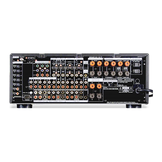
The model and serial numbers are located on the rear panel. Record the serial number
in the space provided below. Refer to them whenever you call upon your Sony dealer
regarding this product.
Model No.
STR-DA5ES
STR-DA3ES
© 2001 Sony Corporation
4-237-333-14(2)
Serial No.
Advertisement
Table of Contents

Related Manuals for Sony STR-DA5ES Primary


Summary of Contents for Sony STR-DA5ES Primary
-
Page 1: Operating Instructions
Operating Instructions Owner’s Record The model and serial numbers are located on the rear panel. Record the serial number in the space provided below. Refer to them whenever you call upon your Sony dealer regarding this product. Model No. STR-DA5ES STR-DA3ES ©... - Page 2 EXTENSION CORD, RECEPTACLE OR OTHER OUTLET UNLESS THE BLADES CAN BE FULLY INSERTED TO PREVENT BLADE EXPOSURE. If you have any questions about this product, you may call; Sony Customer Information Center 1-800-488- 7669. The Number below is for the FCC related matters only.
-
Page 3: Table Of Contents
Table of Contents Features ... 4 Parts Identification Main unit ... 5 Hooking Up the Components Required cords ... 6 Antenna hookups ... 7 Audio component hookups ... 8 Video component hookups ... 9 Digital component hookups ... 10 Multi channel input hookups ... 12 Other hookups ... -
Page 4: Features
Features 7.1 channel mode This receiver incorporates a 6 channel amplifier. It can reproduce the sound of movies (etc.) encoded in 6.1 channel audio through front (L/R), center, surround (L/R), surround back, and sub woofer speakers. This receiver also lets you enjoy a 7.1 channel mode. The 7.1 channel mode uses DSP (Digital Signal Processor) technology to reproduce the Surround Back channel in stereo (L/R) (page 28). -
Page 5: Parts Identification
Parts Identification The items are arranged in alphabetical order. Refer to the pages indicated in parentheses ( ) for details. Main unit 1 23 2CH qg (31, 33) 2ND ROOM (STR-DA3ES only) eh (29, 30) 2ND/3RD ROOM (STR-DA5ES only) eh (29, 30) 6.1CH indicator ql 6.1CH DECODING qk (34) A.F.D. -
Page 6: Hooking Up The Components
Hooking Up the Components Required cords Before you get started • Turn off the power to all components before making any connections. • Do not connect the AC power cord until all of the connections are completed. • Be sure to make connections firmly to avoid hum and noise. •... -
Page 7: Antenna Hookups
Antenna hookups FM wire antenna (supplied) ANTENNA COAXIAL DIGITAL /SACD OPTICAL ND/DAT OPTICAL MD/DAT OPTICAL TV/SAT OPTICAL PHONO DVD/LD OPTICAL /SACD COAXIAL DVD/LD COAXIAL SIGNAL GND ASSIGNABLE Notes on antenna hookups • To prevent noise pickup, keep the AM loop antenna away from the receiver and other components. -
Page 8: Audio Component Hookups
Audio component hookups For details on the required cords (A – H), see page 6. Note on audio component hookups If your turntable has a ground wire, connect it to the U SIGNAL GND terminal. MD or DAT deck INPUT OUTPUT LINE LINE Turntable... -
Page 9: Video Component Hookups
Video component hookups COMPONENT VIDEO ANTENNA COAXIAL DIGITAL /SACD OPTICAL ND/DAT OPTICAL MD/DAT OPTICAL TV/SAT OPTICAL PHONO DVD/LD OPTICAL /SACD COAXIAL To the front DVD/LD panel COAXIAL SIGNAL GND ASSIGNABLE Camcorder or video game * You can display the SET UP, SURROUND, LEVEL, EQ parameters and selected sound field by pressing ON SCREEN. -
Page 10: Digital Component Hookups
You can also connect an LD player with an RF OUT jack via an RF demodulator, like the Sony MOD-RF1 (not supplied). You can select the input mode for your digital components. See “INPUT MODE” on page 27. - Page 11 Connect the digital output jacks of your MD or DAT deck to the receiver’s digital input jack and connect the digital input jacks of your MD or DAT deck to the receiver’s digital output jack. These connections allow you to make digital recordings of TV broadcasts, etc. MD or DAT deck DIGITAL OPTICAL...
-
Page 12: Multi Channel Input Hookups
Multi channel input hookups Although this receiver incorporates a multi channel decoder, it is also equipped with multi channel input jacks. These connections allow you to enjoy multi channel software encoded in formats other than Dolby Digital and DTS. If your DVD player is equipped with multi channel output jacks, you can connect them directly to the receiver to enjoy the sound of the DVD player’s multi channel decoder. -
Page 13: Other Hookups
SUB WOOFER SUB WOOFER MULTI CHANNEL INPUT 1 PRE OUT • If you have a Sony CD changer with a COMMAND MODE selector If your CD changer’s COMMAND MODE compatible selector can be set to CD 1, CD 2, or CD 3, be sure to set the command mode to “CD 1”... -
Page 14: Connecting The Ac Power Cord
Other hookups (continued) S-LINK CONTROL S hookup If you have a S-LINK CONTROL S- compatible Sony TV, satellite tuner, monitor, DVD player or VCR, use an audio/video/ control S connecting cord (supplied) or a control S connecting cord (supplied) to connect the CTRL S (STATUS) IN (for TV, satellite tuner, or monitor) or OUT (for VCR, etc.) jack... - Page 15 If you connect other audio/video components to the AC OUTLET(s) on the receiver, the receiver will supply power to the connected component(s), allowing you to turn the whole system on or off when you turn the receiver on or off. Caution Make sure that the total power consumption of the component(s) connected to the receiver’s AC...
-
Page 16: Hooking Up And Setting Up The Speaker System
Hooking Up and Setting Up the Speaker System Speaker system hookup Required cords A Speaker cords (not supplied) (–) B Monaural audio cord (not supplied) Black C Audio cord (not supplied) White (L) Red (R) Active sub woofer INPUT AUDIO VIDEO 2 VIDEO 1 CONTROL S... - Page 17 Tips • You can connect an active sub woofer to either of the two jacks. The remaining jack can be used to connect a second active sub woofer. As the active sub woofer does not have the directivity, you can place it wherever you want.
-
Page 18: Speaker Impedance
Speaker system hookup (continued) Another room hookups You can connect the speakers to use in another room to the SPEAKERS 3RD ROOM jacks (STR-DA5ES) or the SPEAKERS 2ND ROOM jacks (STR-DA3ES). Make sure to connect correctly as indicated on the rear panel. VIDEO 2 CONTROL S S2 VIDEO... -
Page 19: Performing Initial Setup Operations
Performing initial setup operations Once you have hooked up the speakers and turned on the power, clear the receiver’s memory. Then specify the speaker parameters (size, position, etc.) and perform any other initial setup operations necessary for your system. To check the audio output during settings (to set up while outputting the sound), check the connection (see page 25). -
Page 20: Specifying The Speaker Parameters
Multi channel surround setup (continued) When placing surround speakers behind you Note Do not place the center speaker farther away from the listening position than the front speakers. When setting up the surround back speaker, set the speaker at least 3 feet behind the listening position. It is recommended to place the speaker at an equal distance from the surround left and right speakers. - Page 21 x Center speaker size (CENTER) • If you connect a large speaker that will effectively reproduce bass frequencies, select “LARGE”. Normally, select “LARGE”. However, if the front speakers are set to “SMALL”, you cannot set the center speaker to “LARGE”. •...
- Page 22 Multi channel surround setup (continued) x Surround back speaker single or double (SURR BACK L/R) • When the center speaker is set to “NO” and you use the center speaker as a surround back right speaker and use the surround back speaker as a surround back left speaker, select “YES”.
- Page 23 The receiver allows you to input the speaker position in terms of distance. However, it is not possible to set the center speaker further than the front speakers. Also, the center speaker cannot be set more that 5 feet closer than the front speakers. Likewise, the surround and surround back speakers can not be set farther away from the listening position than the front speakers.
- Page 24 Multi channel surround setup (continued) * These parameters are not available when “Surround speaker size (SURROUND)” is set to “NO”. ** This parameter is not available when “Surround back speaker size (SURR BACK)” is set to “NO”. The surround/surround back speaker position parameter is designed specifically for implementation of the Digital Cinema Sound modes in the “VIRTUAL”...
-
Page 25: Checking The Connections
Adjusting the speaker level Use the remote while seated in your listening position to adjust the level of each speaker. Note The receiver incorporates a new test tone with a frequency centered at 800 Hz for easier speaker level adjustment. Press ?/1 to turn on the receiver. -
Page 26: Basic Operations
Basic Operations Selecting the component FUNCTION control Turn FUNCTION control to select the component you want to use. To select Rotate to light VIDEO 1 or VIDEO 2 Camcorder or VIDEO 3 video game DVD or LD player DVD/LD TV or satellite tuner TV/SAT Tape deck TAPE... -
Page 27: Input Mode
INPUT MODE Press INPUT MODE to select the input mode for your digital components. You can also select the COAXIAL or OPTICAL audio input of other functions assigned by AUDIO SPLIT. Each time you press the button, the input mode of the currently selected component switches. -
Page 28: Setting To The 7.1 Channel Mode
Selecting the component (continued) PHONES Use to connect headphones. When the headphones are connected, selectable sound fields are HEADPHONE (2CH), HEADPHONE (DIRECT), and HEADPHONE THEATER (see page 33). Note When “HEADPHONE (MULTI 1)” or “HEADPHONE (MULTI 2)” appears in the display while the headphones are connected, only the front L/ R signals of the multi channels are output from the headphones. -
Page 29: Listening To The Sound In Another Room
Listening to the sound in another room SPEAKERS AUDIO IN Stereo amplifier You can select the analog audio signals for output to a stereo amplifier or speakers in another room. For details on the connection, see pages 14 and 18. To output the sound using the 2ND ROOM OUT jacks (2nd room) (STR-DA5ES) Press 2ND/3RD ROOM... -
Page 30: Changing The Display
Listening to the sound in another room (continued) (For STR-DA3ES) The same source is output to the 2nd and the 3rd room. Set the SPEAKER switch to “MAIN + 2ND ROOM”. The indicator lights up. Press 2ND ROOM, then turn the jog dial to select the analog audio signals. -
Page 31: Enjoying Surround Sound
DCS is the concept name of the surround technology for home theater developed by Sony. DCS uses the DSP (Digital Signal Processor) technology to reproduce the sound characteristics of an actual cinema cutting studio in Hollywood. - Page 32 “VIRTUAL MATRIX 6.1” playback function (page 34). • SEMI C.STUDIO EX A reproduces the sound characteristics of Sony Pictures Entertainment’s classic editing studio. • SEMI C.STUDIO EX B reproduces the sound characteristics of Sony Pictures Entertainment’s mixing studio which is one of the most up-to- date facilities in Hollywood.
- Page 33 x CHURCH Reproduces the acoustics of a stone church. x OPERA HOUSE Reproduces the acoustics of an opera house. x JAZZ CLUB Reproduces the acoustics of a jazz club. x DISCO/CLUB Reproduces the acoustics of a discotheque/ dance club. x LIVE HOUSE Reproduces the acoustics of a 300-seat live house.
- Page 34 Selecting a sound field (continued) NIGHT MODE Allows you to retain a theater like environment, at low volume levels even late at night. Even at a low volume level, you can clearly hear the dialogues and adjust the volume in small steps. This function can be used with other sound field (pages 31–33).
- Page 35 Discrete 6.1 channel signals are DVD specific signals not used in movie theaters. Set 6.1 Channel Decoding to “AUTO” to play the discrete 6.1 channel signals. Set 6.1 Channel Decoding to “ON” to activate Sony DCMD and play 6.1 channel signals equivalent to those that would be used in a movie theater.
-
Page 36: Understanding The Multi Channel Surround Displays
Understanding the multi channel surround displays L.F.E. 1 SW: Lights up when sub woofer selection is set to “YES” and the receiver detects that the disc being played back does not contain the LFE channel signal. While this indicator lights up, the receiver creates a sub woofer signal based on the low frequency components of the front channels. - Page 37 qa MPEG: Lights up when MPEG signals are input. Note Only the front 2 channels are compatible with MPEG format. Multi channel surround sound is downmixed and output from the front 2 channels. qs DTS: Lights up when DTS signals are input. When playing a DTS format disc, be sure that you have made digital connections and that INPUT MODE is NOT set to ANALOG 2CH...
-
Page 38: Customizing Sound Fields
Customizing sound fields By adjusting the surround parameters and the equalization of the front, center, surround, and surround back speakers, you can customize the sound fields to suit your particular listening situation. Once you customize a sound field, the changes are stored in the memory indefinitely. - Page 39 2ch decode mode (2CH MODE) (STR-DA5ES only) Lets you specify the type of decoding for the 2 channel source. This receiver incorporates with Dolby Surround Pro Logic II, and DTS Neo:6. Each of these has movie mode and music mode, and the receiver can reproduce the 2 channel sound in 5.1 channel through Dolby Surround Pro Logic II, or 6 channel through DTS Neo:6.
- Page 40 Customizing sound fields (continued) Effect level (EFFECT LEVEL) Lets you adjust the “presence” of the current surround effect. Wall type (WALL) Lets you control the level of the high frequencies to alter the sonic character of your listening environment by simulating a softer (S) or harder (H) wall.
- Page 41 Initial settings Parameter Initial setting TEST TONE* PHASE NOISE* PHASE AUDIO* FRONT L__I__R Center SURROUND L__I__R Center SUR.BACK L__I__R Center CENTER LEVEL 0 dB SURROUND LEVEL 0 dB SUR.BACK LEVEL 0 dB S.WOOFER LEVEL 0 dB LFE MIX LEVEL 0 dB D.RANGE COMP.
-
Page 42: Adjusting The Equalizer
Customizing sound fields (continued) Dynamic range compressor (D. RANGE COMP.) Lets you compress the dynamic range of the sound track. This may be useful when you want to watch movies at low volumes late at night. We recommend using the “MAX” setting. •... - Page 43 Front speaker bass adjustment (Gain/Frequency) Lets you adjust the gain and frequency of bass. Front speaker midrange adjustment (Gain/Frequency) Lets you adjust the gain and frequency of midrange. Front speaker midrange bandwidth Lets you adjust the width of the midrange band. •...
-
Page 44: Receiving Broadcasts
Receiving Broadcasts Before receiving broadcasts, make sure you have connected FM and AM antennas to the receiver (see page 7). Direct tuning You can enter a frequency of the station you want directly by using the numeric buttons on the supplied remote. Rotate FUNCTION to select TUNER. -
Page 45: Preset Tuning
Preset tuning After you have tuned in stations using Direct Tuning or Automatic Tuning, you can preset them to the receiver. Then you can tune in any of the stations directly by entering its 2-character preset code using the supplied remote. -
Page 46: Other Operations
Other Operations Naming preset stations and program sources You can enter a name of up to 8 characters for preset stations and program sources. These names (for example, “VHS”) appear in the receiver’s display when a station or program source is selected. Note that no more than one name can be entered for each preset station or program source. -
Page 47: Using The Sleep Timer
Notes • You cannot record a digital audio signal using a component connected to the analog TAPE OUT or MD/DAT OUT jacks. To record a digital audio signal, connect a digital component to the DIGITAL MD/DAT OUT jacks. • Sound adjustments do not affect the signal output from the TAPE OUT or MD/DAT OUT jacks. -
Page 48: Adjustments Using The Set Up Button
Adjustments using the SET UP button The SET UP button allows you to make the following adjustments. Press SET UP. Press the cursor buttons ( select the parameter you want to adjust. Turn the jog dial to select the setting you want. - Page 49 (AUTO FUNCTION) Lets you switch the function of this receiver to the Sony components connected via CONTROL A1 cords (see page 13) automatically when the connected component is set to play mode. x 2nd room speaker (2ND ROOM SP)
- Page 50 (COMMAND MODE) Lets you select the command mode of the remote. Change the command mode when you use 2 Sony receivers in the same room. x Test tone mode (T.TONE) Lets you select the test tone output mode (page 25).
-
Page 51: Control A1 Control System
The CONTROL A1 control system has been updated to the CONTROL A1 which is the standard system in the Sony 300 disc CD changer and other recent Sony components. Components with CONTROL A1 jacks are compatible with components with CONTROL A1 , and can be connected to each other. -
Page 52: Basic Functions
In this case, use the connecting cord for your connection. When using a commercially available cord, use a monaural (2P) mini-plug cord less than 2 meters long, with no resistance (like the Sony RK-G69HG). Basic Functions The CONTROL A1... -
Page 53: Operations Using The Remote
Operations using the remote (STR-DA5ES only) Two remotes are supplied with STR-DA5ES (RM-LJ305, RM-US105). For details, refer to the following pages respectively. RM-LJ305: pages 53–74 RM-US105: pages 75–81 For the remote (RM-PP505L) supplied with STR-DA3ES, refer to the separate operating instructions. -
Page 54: Location Of Parts And Basic Remote Operations
Before you use your remote (continued) Setting up the remote At the time of shipping, the remote has not been customized to your receiver yet. Before you use the remote for the first time, do the procedure below to set up the remote so that it can control your receiver properly. - Page 55 Parts Description 1 Display window The current status of the selected component or a list of selectable items appears here. Note Characters other than letters of the alphabet or numbers may be displayed incorrectly on the remote, even if they appear correctly in the display window on the main unit.
- Page 56 Location of parts and basic renite operations (continued) qa DIMMER button The function of this button is same as the DIMMER button on the receiver. See page qs AUDIO SPLIT button The function of this button is same as the AUDIO SPLIT button on the receiver.
- Page 57 “Programming the Remote” on page 64. If you press the ?/1 switch (2) at the same time, it will turn off the main component and other Sony audio/video components (SYSTEM STANDBY). Note The function of the AV ?/1 switch changes automatically each time you press FUNCTION (4).
- Page 58 Table of buttons used to control each component When you program the remote to control the following Sony or non-Sony components, you can use the buttons on the remote that are marked with circles. Note, however, that some buttons may not operate your component.
- Page 59 Table of operations that appear when you press the SUB button Press SUB to display a list of operations that the corresponding buttons are not found on the remote. The contents of the lists will vary according to the currently selected component. The following table shows the items in each list and the function of each item.
- Page 60 Location of parts and basic renite operations (continued) Component Item(s) VIDEO CD TIME player INDEX + INDEX – CD Player DISC TRACK CONTINUE Selects Continuous Play. SHUFFLE PROGRAM REPEAT MD deck DISPLAY CONTINUE Selects Continuous Play. SHUFFLE PROGRAM REPEAT MENU(EDIT)/ Selects editing operation CLEAR Tape deck A-REC...
- Page 61 “SIDE A/B” appears for non-Sony LD players. b) Only with Sony TVs with the picture-in-picture function. c) Only with Sony TVs that supports the wide-picture mode. d) Only with the Sony CD changer. Note If you have programmed the remote to control non- Sony components, note the following: –...
-
Page 62: Using The Lists
Using the lists Chart of lists See the treelike chart below for the list hierarchy. Details on how to access each list is given from page 63. Some items have sub-lists that appear when you press SUB (see pages 59–60). VIDEO1 VIDEO2 VIDEO3... -
Page 63: Selecting A Component
Selecting a component Basic procedure for selecting a component Do the procedure below to select a component from the function list. Press FUNCTION. The function list appears. The items in the list correspond with the jacks on the receiver. Move the easy scroll key to select a component from the list, then press the key to enter the selection. -
Page 64: Programming The Remote
Using the lists (continued) If you selected a Sony CD changer Move the easy scroll key. The DISC MEMO list appears. Move the easy scroll key to select a disc, then press the key to enter the selection. Start playback. - Page 65 (“Kenwood”, for example), then press the key to enter the selection. When programming the remote to control Sony component Select “Sony.” Programming is now completed. To cancel programming Move the easy scroll key to select “Exit” or “Cancel”...
- Page 66 Using the lists (continued) Move the easy scroll key to select “MACRO1” (or “MACRO2”), then press the key to enter the selection. The program list appears. Move the easy scroll key to select the macro step number (“1-NO SET” for example) then press the key to enter the selection.
- Page 67 2 Move the easy scroll key to select “NO SET”, then press the key to enter selection. To turn off all Sony components (SYSTEM STANDBY) 1 In step 4, move the easy scroll key to select “Common”, then press the key to enter selection.
-
Page 68: Learning The Commands Of Your Components
Using the lists (continued) Learning the commands of your components By using the Learning function, it is possible for this commander to perform learned operations. Setting remote control codes that are not stored in the commander When a remote control code is not one of the presets stored in the commander, it is possible for the commander to learn the code using the Learning function. - Page 69 CD in each slot of a CD changer* from the receiver. * Appears only when you have selected a Sony CD changer (5, 50, 200, 300, or 400 discs) connected to the receiver using the CONTROL A1 cable.
- Page 70 • You can download the data only from the Sony CD changer (5, 50, 200, 300, or 400 discs) connected to the receiver using the CONTROL A1 cable.
- Page 71 Adjusting the level parameters Press SET UP. The set up list appears. Move the easy scroll key to select “RECEIVER”, then press the key to enter the selection. The RECEIVER list appears. Move the easy scroll key to select “LEVEL”, then press the key to enter the selection.
- Page 72 Notes • Switching to VIDEO 1–4 input may not be automatic on all Sony TVs. This is because some TVs cannot receive remote control codes immediately after being turned on. • When you select “(Off)” in step 4, the TV input does not switch.
- Page 73 Switching the COMMAND MODE You can switch the command mode (AV SYSTEM1 or AV SYSTEM2) of the remote. If the command mode of the receiver and the remote is different, you cannot use the remote to operate the receiver. Press SET UP. The set up list appears.
- Page 74 Using the lists (continued) To operate the tuner of the receiver in the main room To operate the tuner built in the receiver in the main room in the 3rd room mode, select the same command mode of the receiver in the SERVER list.
-
Page 75: Using The Remote Rm-Us105
Using the remote RM-US105 This remote can be used in the following 3 ways. x When using as a simplified remote This remote can be used as a simplified substitute of the supplied remote (RM-LJ305) to operate STR-DA5ES. The following operations are possible: •... - Page 76 2nd room. When you are using a Sony receiver in the 2nd room, you can adjust volume or switch the source by setting the same command modes to the remote and the receiver. Besides, you can set the remote to control the power on/off, adjust volume, and so on while the remote is set to 2nd room mode.
-
Page 77: Inserting Batteries Into The Remote
x When using in the 3rd room Main room Audio/Video components STR-DA5ES IR repeater (not supplied) AV ?/1 SYSTEM STANDBY FUNCTION PUSH ENTER > CH/PRESET/D.SKIP – BASS MASTER BOOST MUTING – RM-LJ305 Using the optional IR repeater as shown above You can turn on/off the sound output from SPEAKERS 3RD ROOM jacks, switch the sources, or adjust the volume of the STR-DA5ES in the main room. - Page 78 Tape deck B MD/DAT MD deck CD/SACD CD/SACD player TUNER Built-in tuner LD player — SOURCE 2ND ROOM, 3RD ROOM only The setting cannot be changed. * These buttons operate receivers with COMMAND MODE set to “AV SYSTEM1” or other Sony receivers.
- Page 79 USE MODE indicator * These buttons operate receivers with COMMAND MODE set to “AV SYSTEM1” or other Sony receivers. ** The function of these buttons switches automatically each time you press the function buttons (3).
- Page 80 Using the RM-US105 remote (continued) To set to the 2nd room mode Press USE MODE. The current remote mode button slowly lights up 5 times. Press 2ND ROOM while the button blinks. The command mode has been set to the 2nd room mode.
- Page 81 To change the button assignments You can change the factory settings of the function buttons to suit the components in your system. For example, if you connect a LD player to the VIDEO 2 jacks on the receiver, you can set the VIDEO2 button on this remote to control the LD player.
-
Page 82: Additional Information
If you have any question or problem concerning your receiver, please consult your nearest Sony dealer. Troubleshooting If you experience any of the following... - Page 83 There is no sound or only a very low-level sound is heard. • Check that the speakers and components are connected securely. • Check that you have selected the correct component on the receiver. • Check that the SPEAKERS selector is not set to OFF (see page 27).
- Page 84 • Make sure you select the correct function on the remote. • When you operate a programmed non-Sony component, the remote may not function properly depending on the model and the make of the component.
-
Page 85: Specifications
Reference sections for clearing the memory To clear All memorized settings page 19 Customized sound fields page 42 All the settings in the remote page 74 Specifications AUDIO POWER SPECIFICATIONS POWER OUTPUT AND TOTAL HARMONIC DISTORTION: With 8 ohm loads, both channels driven, from 20 –... - Page 86 Specifications (continued) FM tuner section Tuning range Antenna terminals Sensitivity Mono: Stereo: Usable sensitivity Mono: Stereo: Harmonic distortion at 1 kHz Mono: Stereo: Separation Frequency response Selectivity AM tuner section Tuning range With 10-kHz tuning scale: 530 – 1710 kHz With 9-kHz tuning scale: 531 –...
-
Page 87: Tables Of Settings Using Surround, Level, Eq, And Set Up Buttons
Tables of settings using SURROUND, LEVEL, EQ, and SET UP buttons You can make various settings using the LEVEL, SURROUND, EQ, SET UP buttons, jog dial, and cursor buttons. The tables below show each of the settings that these buttons can make. Press Press to select... - Page 88 Tables of settings using SURROUND, LEVEL, EQ, and SET UP buttons (continued) Press Press FRONT BASS GAIN FRONT BASS FREQUENCY FRONT MID GAIN FRONT MID FREQUENCY FRONT MID BANDWIDTH FRONT TREBLE GAIN FRONT TREBLE FREQUENCY CENTER BASS GAIN CENTER BASS FREQUENCY CENTER MID GAIN CENTER MID FREQUENCY CENTER MID BANDWIDTH...
- Page 89 Press Press to select SET UP FRONT SP CENTER SP SURROUND SP SURR BACK SP SURR BACK L/R SUB WOOFER FRONT CENTER SURROUND SURR BACK SUB WOOFER S.W PHASE DISTANCE UNIT SURR POSI. SURR HEIGHT SURR BACK HGT. FRONT SP > CENTER SP >...
-
Page 90: Adjustable Parameters For Each Sound Field
Adjustable parameters for each sound field The adjusted SURROUND parameters are stored in each sound field. The adjusted LEVEL parameters are applied to all the sound fields. A.F.D. NORMAL SURROUND CINEMA STUDIO EX A CINEMA STUDIO EX B CINEMA STUDIO EX C SEMI C.STUDIO EX A SEMI C.STUDIO EX B SEMI C.STUDIO EX C... - Page 91 < FRONT A.F.D. NORMAL SURROUND CINEMA STUDIO EX A CINEMA STUDIO EX B CINEMA STUDIO EX C SEMI C.STUDIO EX A SEMI C.STUDIO EX B SEMI C.STUDIO EX C NIGHT THEATER MONO MOVIE STEREO MOVIE V.MULTI DIMENSION VIRTUAL MULTI REAR V.SEMI M.DIMENSION VIRTUAL ENHANCED A VIRTUAL ENHANCED B...
- Page 92 Adjustable parameters for each sound field (continued) A.F.D. NORMAL SURROUND CINEMA STUDIO EX A CINEMA STUDIO EX B CINEMA STUDIO EX C SEMI C.STUDIO EX A SEMI C.STUDIO EX B SEMI C.STUDIO EX C NIGHT THEATER MONO MOVIE STEREO MOVIE V.MULTI DIMENSION VIRTUAL MULTI REAR V.SEMI M.DIMENSION...
- Page 93 < < BASS GAIN A.F.D. NORMAL SURROUND CINEMA STUDIO EX A CINEMA STUDIO EX B CINEMA STUDIO EX C SEMI C.STUDIO EX A SEMI C.STUDIO EX B SEMI C.STUDIO EX C NIGHT THEATER MONO MOVIE STEREO MOVIE V.MULTI DIMENSION VIRTUAL MULTI REAR V.SEMI M.DIMENSION VIRTUAL ENHANCED A VIRTUAL ENHANCED B...
- Page 94 Adjustable parameters for each sound field (continued) A.F.D. NORMAL SURROUND CINEMA STUDIO EX A CINEMA STUDIO EX B CINEMA STUDIO EX C SEMI C.STUDIO EX A SEMI C.STUDIO EX B SEMI C.STUDIO EX C NIGHT THEATER MONO MOVIE STEREO MOVIE V.MULTI DIMENSION VIRTUAL MULTI REAR V.SEMI M.DIMENSION...
- Page 96 Sony Corporation Printed in Malaysia...