Table of Contents
Advertisement
Advertisement
Table of Contents

Related Manuals for Metrol RC Series


Summary of Contents for Metrol RC Series
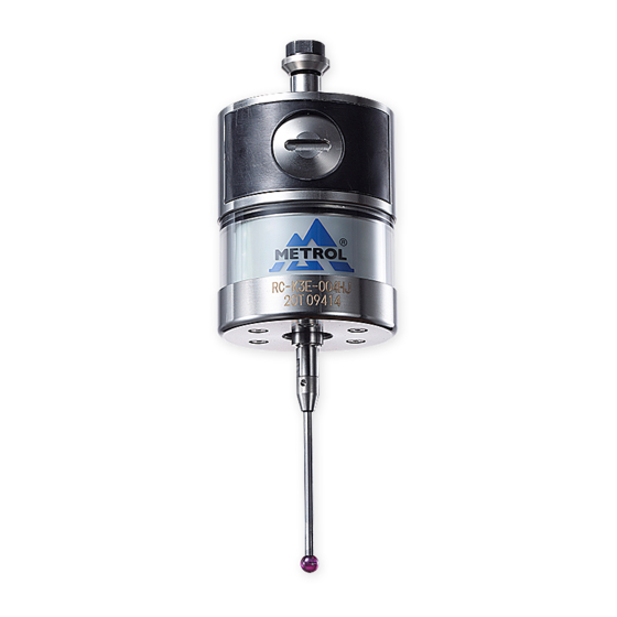
- Page 1 RC series Instruction Manual...
- Page 2 ■ Technical conformity marks Metrol Co., Ltd. Model : RC-K3E Power : 3.6V R 001-A00026 CMIIT ID : 2012DJ3660 Made in Japan FCC ID : AORMETROLRCK3E002 This device complies with Part 15 of the FCC Rules. Operation is subject to the following two conditions: 1-this device may not cause harmful interference.
-
Page 3: Table Of Contents
INDEX 1. Before using ....P1−2 Terms of Warranty ....Usage precautions . - Page 4 A replacement product will be provided on an exchange basis or the malfunctioned product will be repaired free of charge within the warranty period. If the product is or becomes defective and that at the sole discretion of METROL, the defects due to faulty materials or workmanship.
- Page 6 Applications in harsh environments ( special environments requiring heat resistance, vacuum and the like ) *Although METROL believes that sound reliability in harsh environments is one of the characteristics of our products, there are still cases in which it is difficult to ascertain actual circumstances.
-
Page 7: Usage Precautions
・Try to keep cable lengths as short as possible at all times. 4 ) Product usage Use of this product in a manner other than that specified by METROL may cause a decrease in the guaranteed performance and functions of the product. - Page 8 NOTE www.baysupply.com...
- Page 9 2. Basic specification The transmitter communicates with the receiver using 2.4GHz ISM band. The receiver receives touching signal, battery alarm signal and communication alarm signal from the transmitter and outputs the decoded signals to CNC controller through the cable. This system gains FCC, CE, TELEC (JAPAN), SRCC (CHINA) and RoHS, WEEE certification. 2-1 Common specification Frequency range 2400 - 2480 MHz...
- Page 10 2-3-1 Wiring diagram BLUE +24V BLUE / BLACK PROBE STATUS 1 VIOLET +24V VIOLET / BLACK LOW BATTERY GREEN +24V GREEN / BLACK ERROR 4.7kΩ WHITE MACHINE START + BROWN MACHINE START 0V YELLOW SKIP + GRAY SKIP 0V ORANGE PROBE STATUS 2b +24V ( 12V-30V ) BLACK...
-
Page 11: Transmitter
3. Software specification 3-1 Transmitter Transmitter has 3 modes. 1 Sleep mode When M code (power ON signal) does not exist, transmitter operates in the Sleep mode to suppress power consumption. Transmitter periodically attempts to make communication witht the receiver. Transmitter and receiver communicate with each other and exchange data every 14 - 27 seconds, if the communication is possible. -
Page 12: Receiver
3-2 Receiver Receiver has 3 modes. 1 Sleep mode Receiver watches 2400-2480 MHz range anytime and find out the empty channel. It waits until M code (power ON signal) is sent, continuously sending radio wave state (empty channel information) to the transmitter. If the communication with the transmitter is successful, the Com. - Page 13 4. Matching transmitter and receiver It is necessary to match the transmitter and receiver when first installing the system. Matching is also required when replacing either the transmitter or the receiver. Matching can be performed anywhere within the range of movement of the system. 1 Receiver matching procedure 1) Remove the cover of the receiver.
- Page 14 NOTE www.baysupply.com...
-
Page 15: 5. Parameter Switch (Dip Switch
5. Parameter switch (DIP switch) 5-1 Details of parameter switch (DIP switch) LOW BATTERY NC (Nomally close) PROBE STATUS1 PROBE STATUS 2a, 2b ERROR NC (Nomally close) MACHINE START LEVEL PULSE (Nomally close) PULSE (Nomally close) Matching mode ON Mode changeover switch LEVEL (Nomally open)... - Page 16 Probe status 2a = Skip signal Parameter switch No. ON/OFF Output signal Description PROBE STATUS 2a, 2b LEVEL output PROBE STATUS 2a, 2b PULSE output NO (Nomally open) PROBE STATUS 2a, 2b NC (Nomally close) PROBE STATUS 2a, 2b 3 = OFF 3, 4 = OFF Sensor ON Sensor OFF...
-
Page 17: 5. Parameter Switch (Dip Switch
5. Parameter switch (DIP switch) Parameter switch No. ON/OFF Output signal Description MACHINE START PULSE input MACHINE START LEVEL input 7 = OFF 20ms≦ 10ms≦ 1st PULSE 2nd PULSE 3rd PULSE M code (Measuring start) M code (Measuring finish) M code (Measuring start) 7 = ON M code (Measuring start) M code (Measuring start) - Page 18 5-2 Details of LED display 1. Power LED flashing 500ms Repeat 500ms 2. Com. LED flashing 1) Transmitting NG 2) Transmitting NG 1700ms 160ms 1680ms Repeat Repeat 300ms 80ms 80ms 3) Unstable communication in Measuring mode: early stage 11ms Repeat 4) Incommunicable in Measuring mode:output the error signal 160ms 160ms...
-
Page 19: 5. Parameter Switch (Dip Switch
5. Parameter switch (DIP switch) 6) Matching phase Seeking for the channel Matching complete 420ms 840ms Repeat Repeat 80ms 160ms 3. Batt. LED flashing Matching complete DIP switch #8 OFF 1) Matching phase 2) Inside memory problem 500ms 200ms Repeat Repeat 500ms 200ms... - Page 20 4. I/O circuit PROBE STATUS 1 LOW BATTERY +24V +24V Max 55V 50mA Max 55V 50mA PROBE STATUS 1 LOW BATTERY ERROR MACHINE START 4.7kΩ +24V MACHINE START + Max 55V 50mA Max 70mA MACHINE START 0V ERROR PROBE STATUS 2a (SKIP) PROBE STATUS 2b SKIP + PROBE STATUS 2b...
- Page 21 Transmission range when conbining transmitter and receiver Install the receiver at a location so that it can maintain communication over the movement range of the transmitter. RC sensor series are uninterrupted by any obstacles in between the transmitter and reciver. Use the communication LED display of the receiver as a reference for determining the optimum installation position.
- Page 22 NOTE www.baysupply.com...
-
Page 23: Receiver Installation
7. Receiver installation ■For external installation Inside Outside machine machine φ 10.5 Splash guard φ Recommended monting holes Splash guard ■For internal installation Inside Outside machine machine φ Recommended monting holes Splash guard Inside Outside machine machine Splash guard ■Attachment of direct cable •... - Page 24 NOTE www.baysupply.com...
-
Page 25: Stylus Attachment
8. Transmitter installation 8-1 Stylus attachment (RC-K3E) 2. Tighten using the hexagonal wrench and spanner. 1. Insert the stylus Hexagonal wernch 0.89mm Spanner S907 www.baysupply.com... -
Page 26: Installing The Battery
8-2 Installing the battery ・Confirm the alignment of the battery electrodes when inserting the battery. ・Does not function properly if a dead battery is mistakenly inserted into the transmitter. ・Do not allow coolant or cuttings to get inside the battery case. 1. -
Page 27: Attachment Of The Transmitter To Shank
8. Transmitter installation 8-3 Attachment of the transmitter to shank 1. Attach the shank to the transmitter. 2. Tighten two transmitter fixing screws (corn point fixing screws) with a hexagonal wrench. Mounting part of the shank 17.5≦ 4-M4 2-M4 (4 magnification) For centering transmitter For fixing transmitter (flat-tipped fixing screw) -
Page 28: Stylus Centering Adjustment
8-4 Stylus centering adjustment (mainly for RC-K3E) Caution:It is necessary to recheck the centering adjustment if the transmitter has been dropped. Absolutely never strike the transmitter when adjusting centering. 1. Adjust centering by pushing and pulling four flat-tipped fixing screws for transmitter centering adjustment with lever type dial gauge or similar tool and fasten them after adjusting. - Page 29 9. Maintenance ■Cleaning the transmitter Wipe the window of the transmitter with a clean cloth to remove any cuttings and other debris such as coolant. Clean the transmitter regularly to maintain the signal transmission capabilities of the transumitter in the optimum state. ■...
- Page 30 NOTE www.baysupply.com...
- Page 31 10. Troubleshooting Problem Possible Cause Corrective Action Dead battery Replace the battery. Transmitter power does not come on. Use of battery other than Replace the battery. recommended battery Check the alignment of Battery is installed improperly the electrodes of the battery. The time the battery has been Wait for at least 15 seconds removed is too short, preventing...
- Page 32 Problem Possible Cause Corrective Action Defective Clean the workpiece or transmitter. Debris present on workpiece or transmitter. Inadequate coupling between probe Check each location and retighten. repeatability or measurement and shank or loose stylus Defective repeatability of sensor Recalibrate the sensor whenever accuracy replacement by ATC the it is changed.
- Page 33 The specifications and descriptions are subject to change without notice due to improvements in products. GM-RC-E-K001 www.baysupply.com...
Need help?
Do you have a question about the RC Series and is the answer not in the manual?
Questions and answers