Table of Contents
Advertisement
Quick Links
Instruction Manual and Replacement Parts List
Mini Verticus
High Pressure Air Compressor Unit
ImVT 120 II (AP)
June 11, 2009
BAUER Compressors, Inc.
1328 Azalea Garden Road
Norfolk, Virginia 23502-1944
1st Edition, Rev. 0 Chg. 10
© 2009 Bauer Compressors, Inc.
MNL-0408
Phone: (757) 855-6006
Fax: (757) 855-6224
www.bauercomp.com
Advertisement
Table of Contents
Troubleshooting

Related Manuals for Bauer Compressors Mini Verticus ImVT 120 II


Summary of Contents for Bauer Compressors Mini Verticus ImVT 120 II
- Page 1 High Pressure Air Compressor Unit ImVT 120 II (AP) June 11, 2009 1st Edition, Rev. 0 Chg. 10 MNL-0408 © 2009 Bauer Compressors, Inc. BAUER Compressors, Inc. Phone: (757) 855-6006 1328 Azalea Garden Road Fax: (757) 855-6224 Norfolk, Virginia 23502-1944...
- Page 2 ImVT 120 II Mini Verticus This information is believed to be accurate by Bauer Compressors, Inc., as of it’s date of publication, but Bauer offers NO WARRANTY regarding the accuracy, or continuing accuracy, of the information set forth herein. Bauer shall not be liable for inaccuracies in, or consequences resulting from, your use of this information.
-
Page 3: Table Of Contents
MNL-0408 Table of Contents CHAPTER 1: - - - - - - - - - - - - - - - - - - - - - INTRODUCTION HOW TO USE THIS MANUAL............................1 1.1.1 Manual Safety Notices ............................... 1 HOW TO USE THE REPLACEMENT PARTS LIST .................... - Page 4 ImVT 120 II Mini Verticus CHAPTER 3:- - - - - - - - - - - - - - MAINTENANCE AND PARTS COMPRESSOR BLOCKS - IK120 II..........................12 3.1.1 Description ..................................12 3.1.2 Component Location ................................12 3.1.3 Air Flow Diagram................................13 3.1.4 Compressor Lubrication ..............................13 3.1.4.1 Description..................................13...
- Page 5 MNL-0408 5.1.2 Chamber Safety Bore ............................... 55 5.1.3 Manual Condensate Drainage ............................56 5.1.4 Model, Serial Number and Part Number Identification ....................56 5.1.4.1 Compressor Dataplate..............................56 5.1.4.2 Purification System Dataplate ............................56 5.1.4.3 Cartridge Installation Dataplate............................ 56 5.1.4.4 Air Processing Cartridge Operating Hours Form ......................57 P2S PURIFICATION SYSTEM MAJOR COMPONENTS ..................
- Page 6 ImVT 120 II Mini Verticus 7.4.5.2.2 For Industrial Units ...............................76 7.4.6 Indicator Lamps................................76 7.4.6.1 PLC Warning and Alarm Lamps ..........................76 7.4.6.1.1 Warning Lamp - Amber..............................76 7.4.6.1.2 Alarm Lamp - Red ................................76 7.4.7 Hour meter..................................76 7.4.8 PLC Control..................................76 7.4.8.1 PLC LED’s ...................................77 7.4.9 Compressor PLC Program Versions ..........................78 7.4.10...
- Page 7 MNL-0408 DIGITAL PRESSURE SWITCH ............................. 96 PROGRAMMING THE PRESSURE SWITCH......................96 8.5.1 Selecting The Display Units............................. 97 8.5.2 Selecting The Unit Display .............................. 97 8.5.3 Selecting The On Point For The Pressure Switch......................97 8.5.4 Selecting The Off Point For The Pressure Switch......................98 8.5.5 locking And Unlocking The Switch..........................
- Page 8 ImVT 120 II Mini Verticus List of Figures CHAPTER 1:- - - - - - - - - - - - - - - - - - - - - INTRODUCTION Figure 1-1 Compressor Identification Plate ..........................2 Figure 1-2 ImVT 120 II (AP) Front Panel..........................4 Figure 1-3 ImVT 120 II (AP) Rear View..........................5 CHAPTER 2:- - - - - - - - PLC CONTROLLED UNIT OPERATIONS...
- Page 9 MNL-0408 Figure 3-34 ACD Manifold Assembly............................49 Figure 3-35 Condensate Drain Valve Assembly........................50 Figure 3-36 Condensate Collector............................. 52 Figure 3-37 Condensate Collector............................. 53 CHAPTER 4: - - - - - - - - - - IK120 II MAINTENANCE SCHEDULE There are no Figures in this Chapter CHAPTER 5: - - - - - - - - - - - - - - - AIR PROCESSING SYSTEM Figure 5-1...
- Page 10 ImVT 120 II Mini Verticus CHAPTER 8:- - - - - - - - PNEUMATIC VALVES AND CONTROLS Figure 8-1 Pressure Maintaining Valve...........................94 Figure 8-2 Safety Valve................................95 Figure 8-3 Digital Pressure Switch............................96 Figure 8-4 Switches and Valves ..............................99 CHAPTER 9:- - - - - - - - - - - - - - - - - - - - - - - - -APPENDIX Figure 9-1 Lifting Devices ..............................103 Figure 9-2...
-
Page 11: How To Use This Manual
CHAPTER 1: INTRODUCTION 1.1 How To Use This Manual This manual contains the operating and maintenance instructions for the Bauer Compressors, Inc. prod- ucts listed on the front cover. All instructions in this manual should be observed and carried out as written to prevent damage or prema- ture wear to the product or the equipment served by it. -
Page 12: How To Use The Replacement Parts List
Serial Number 32165 Date of Manufacture 02/2005 Quantity required Part Number N04860 Part Description Valve Figure 1-1 Compressor Identification Plate BAUER BAUER COMPRESSORS, INC. COMPRESSORS NORFOLK, VIRGINIA U.S.A MODEL NO. BLOCK NO. SERIAL NO. PRESSURE PSIG CAPACITY CHG. RATE MOTOR SPEED... -
Page 13: How To Use The Appendix
Bauer has no control. Such unsafe conditions can lead to accidents that may be life-threatening, cause substantial bodily injury, and/or result in damage to the equipment. Therefore, Bauer Compressors, Inc. can bear no responsibility for equipment in which unapproved repair parts are installed. -
Page 14: Compressor Unit Design
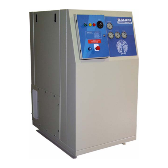
ImVT 120 II Mini Verticus 1.4 Compressor Unit Design The ImVT 120 II Mini Verticus high pressure compressor unit is used for applications in the high pressure range, up to 5000 psig (350 bar). The compressor units of this series are manufactured with a standard type frame with enclosure panels. -
Page 15: Figure 1-3 Imvt 120 Ii (Ap) Rear View
MNL-0408 Figure 1-3 ImVT 120 II (AP) Rear View 1. Securus Monitor 6. Check Valves ® 2. Securus Chamber 7. Purification Chamber Vent Valve ® 3. Final Pressure Switch 8. Final Pressure Gauge 4. Pressure Maintaining Valve 9. Securus Chamber Wrench Holder ®... -
Page 16: Technical Specifications
ImVT 120 II Mini Verticus 1.5 Technical Specifications All technical data is subject to change without prior notice. Medium Free Air Delivery 7.0 scfm ((198 l/min) Inlet pressure atmospheric Operating pressure, max. 5,000 psig (350 bar) Ambient temperature range 41 to 113 °F (5 to 45 °C) 1.5.1 Compressor Block IK120 II Mod. -
Page 17: Pre-Start Checks
MNL-0408 CHAPTER 2: PLC CONTROLLED UNIT OPERATIONS 2.1 Pre-start Checks 1. Ensure that all scheduled maintenance is completed. 2. Check compressor oil level. Refer to Chapter 3. 3. Check Emergency Stop Switch is pulled out. 2.2 Start-up Procedure (See Figure 2-1) 1. -
Page 18: Electric Panel Components
ImVT 120 II Mini Verticus Electric Panel Components See Figure 2-1 Figure 2-1 Electrical Panel Front 1. Compressor Control Switch 4. Hourmeter 2. Warning Light 5. Starter Reset 3. Alarm Light 6. Emergency Stop Switch 2.6.1 Emergency Stop Switch. The Emergency Stop Switch is a switch with a large, red mushroom head. The button must be pulled out for the unit to operate. -
Page 19: Compressor Control Switch
When the warning is illuminated, the unit will still continue to function properly, but will prompt the operator to contact Bauer Compressors for making arrangements to replace the Final Separator. When the Alarm level has been achieved, the compressor will no longer function, and will require the replacement of the Final Separator. -
Page 20: Two Flashes - Securus Monitor (Optional)
ImVT 120 II Mini Verticus ^ WARNING Do not attempt to override the Separator Shutdown Warning. This feature is provided to protect personnel from injury or death. 2.7.2 Two Flashes - Securus Monitor (Optional) The compressor purification system may be equipped with an optional Securus Electronic Moisture ®... -
Page 21: Five Flashes - Carbon Monoxide Monitor (Optional)
When the warning is illuminated, the unit will still continue to function properly, but will prompt the operator to contact Bauer Compressors for making arrangements to replace the separator. When the Alarm level has been achieved, the compressor will no longer function, and will require the replace- ment of the separator. -
Page 22: Compressor Blocks - Ik120 Ii
ImVT 120 II Mini Verticus CHAPTER 3: MAINTENANCE AND PARTS 3.1 Compressor Blocks - IK120 II 3.1.1 Description The IK120 II compressors are used to compress air up to 5000 psi. The compressor is a three cylinder, three stage air cooled, oil lubricated reciprocating compressor. The 3rd stage cylinder is lubricated by means of the forced feed lubrication system, while the other cylinders are splash lubricated. -
Page 23: Air Flow Diagram
MNL-0408 3.1.3 Air Flow Diagram Refer to Figure 3-2. The air is drawn in through intake filter (1), compressed to the final pressure in cyl- inders (2, 3, 4,) and cooled by intercoolers (5, 6) and aftercooler (7). The safety valves (8,9, 10) protect from overpressure in the individual stages. -
Page 24: Type Of Oil
ImVT 120 II Mini Verticus The minimum pressure valve (3) allows for oil pressure indication at a pressure gauge and/or electronic oil pressure monitoring. Figure 3-3 Lubrication Oil Circuit 1. Oil Pump 4. Guide Piston 2. Oil Filter 5. Oil Sight Glass 3. -
Page 25: Oil Level Check
MNL-0408 Figure 3-4 Oil Sight Glass Figure 3-5 Oil Filler Cap Figure 3-6 Removing the Oil Filter Cover Figure 3-7 Replacing the Oil Filter 3.1.4.3 Oil Level Check Check the oil level at the sight gauge on either side of the compressor block (See Figure 3-4) every day before putting the compressor into operation. -
Page 26: Oil Change
ImVT 120 II Mini Verticus 3.1.4.4 Oil Change 1. Run the compressor until it is warm then shut it down. 2. (See Figure 3-5). Remove the cap (1) from the oil filler neck. 3. Drain oil while it is still warm by means of the oil drain tap. ^ CAUTION Replace the oil filter every oil change. -
Page 27: Intake Filter
MNL-0408 3.1.6 Intake Filter. Figure 3-8 Intake Filter 1. Knurled Nut 3. Filter Housing 2. Washer 4. Filter Element 3.1.6.1 Description A dry, micronic filter is used to filter the intake air, see Figure 3-8 The filter cartridge must be changed at regular intervals. See the Maintenance Schedule for the recom- mended interval. -
Page 28: Intermediate Separator
ImVT 120 II Mini Verticus 3.1.7 Intermediate Separator An intermediate separator is mounted on the compressor between the 2nd and 3rd stage. This separator is designed to remove oil and water which accumulates due to the cooling of the medium after the com- pression process. -
Page 29: Cooling
MNL-0408 3.1.8 Cooling 3.1.8.1 General The cylinders of the compressor, the intermediate coolers and the after cooler are air cooled. For this purpose the compressor is equipped with a fanwheel which draws the cooling air through the unit. The fanwheel is driven by the drive motor V-belt and is also used as the compressor flywheel. 3.1.9 Valves and Heads 3.1.9.1 Functional Description The valve heads of the individual stages form the top part of the cylinders. -
Page 30: General Instructions For Changing The Valves
ImVT 120 II Mini Verticus 3.1.9.2 General Instructions for Changing the Valves • Always replace valves as a complete set. • Carefully clean dirty valves. Never use a sharp tool for this purpose. Soak the valves in Varsol and clean with a soft brush. If possible, use an ultrasonic cleaner. •... -
Page 31: Figure 3-12 Ik120 Ii 1St Stage Valve
MNL-0408 Figure 3-12 IK120 II 1st Stage Valve 1. Plate Valve 5. Hex Head Screw 2. Valve Head 6. Washer 3. Washer 7. O-ring 4. Hex Head Screw June 11, 2009 Page 21... -
Page 32: Ik120 Ii 2Nd Stage Valves
ImVT 120 II Mini Verticus 3.1.9.4 IK120 II 2nd Stage Valves 3.1.9.4.1 Removing the Valves of the 2nd Stage Figure 3-13 IK120 II 2nd Stage Valves 1. Cap Nut 5. Pressure Valve Insert 2. Stud 6. Intake Valve 3. Pressure Plug 7. -
Page 33: Reassembling The Valves Of The 2Nd Stage
MNL-0408 11. Clean the valve head. Check that the intake and pressure valve bores are in perfect condition. 12. Using a precision straightedge, check that the underside of the valve head is flat. If necessary use an emery cloth to smooth out the surface. Figure 3-14 Using the Special Tool, P/N 082048 Figure 3-15... -
Page 34: Ik120 Ii 3Rd Stage Valves
ImVT 120 II Mini Verticus 5. Check the pressure valve function and stroke by lifting the valve parts. 6. Ensure the stud (2) is unscrewed, then screw in the pressure plug (3)and tighten. 7. Screw the stud (2) in firmly, fit a new gasket and secure it with the cap nut (1). 8. -
Page 35: Reassembling The Valves Of The 3Rd Stage
MNL-0408 5. Insert two 8mm diameter metal pins, any length, in the holes in the valve head and secure them in a vise with the valve head on top of the vise. The intake valve (1) should be facing up. 6. -
Page 36: Replacement Parts List
ImVT 120 II Mini Verticus 3.1.10 Replacement Parts List Figure 3-18 Crankcase Assembly # KIT Qty Part No. Description Notes ◊ 076743 Crankcase assembly … 076740 Crankcase … 083399 Crankshaft, complete IK120 II … N2638 Roller Bearing … N2635 Circlip …... - Page 37 MNL-0408 Figure 3-18 (cont.) Crankcase Assembly # KIT Qty Part No. Description Notes 13 … 73830 Oil Filling Pipe 14 … N4776 O-ring 15 … SCR-0020 Allen Screw 16 … WAS-0021 Washer 17 a.. N4261 Gasket 18 … PLU-0040 Plug 19 …...
-
Page 38: Figure 3-19 Piston And Cylinder, 1St Stage, Ik120 Ii
ImVT 120 II Mini Verticus Figure 3-19 Piston and Cylinder, 1st Stage, IK120 II # KIT Qty Part No. Description Notes ◊ 080826 Piston and Cylinder Assembly IK120 II … 080734 Cylinder IK120 II N4654 O-ring … 069975 Piston Assembly Items 3 - 61Piston …... -
Page 39: Figure 3-20 Piston And Cylinder, 2Nd Stage
MNL-0408 Figure 3-20 Piston and Cylinder, 2nd Stage # KIT Qty Part No. Description Notes ◊ 062889 Cylinder Assembly … 062477 Cylinder N7063 O-ring … 080383 Guide Cylinder N2640 O-ring … NUT-0119 Self Locking Hex Nut … WAS-0021 Washer … N2790 Stud ◊... -
Page 40: Figure 3-21 Piston And Cylinder, 3Rd Stage
ImVT 120 II Mini Verticus Figure 3-21 Piston and Cylinder, 3rd Stage # KIT Qty Part No. Description Notes ◊ 083400 Cylinder Assembly … 078043 Piston and Sleeve Assembly (See Figure 3-22) N4868 O-ring … 082480 Cylinder N7063 O-ring … 083404 Guide Cylinder NUT-0119... -
Page 41: Figure 3-22 Piston And Sleeve, 3Rd Stage
MNL-0408 Figure 3-22 Piston and Sleeve, 3rd Stage # KIT Qty Part No. Description Notes ◊ 078043 Piston and Sleeve Assembly … † — Piston Available only with 078043 N23755 O-ring … † — Piston Liner Available only with 078043 …... -
Page 42: Figure 3-23 1St Stage Valve Head And Valve, Ik120 Ii
ImVT 120 II Mini Verticus Figure 3-23 1st Stage Valve Head and Valve, IK120 II # KIT Qty Part No. Description Notes ◊ 080688 1st Stage Valve Head Assembly IK120II N26531 Plate Valve IK120 II … 080677 Valve Head IK120 II …... - Page 43 This page is inserted to provide proper page sequencing...
-
Page 44: Figure 3-24 2Nd Stage Valves And Valve Head
ImVT 120 II Mini Verticus Figure 3-24 2nd Stage Valves and Valve Head # KIT Qty Part No. Description Notes ◊ 069955 2nd Stage Valve Head Assembly … 14123 Valve Head 012841 Intake Valve Assembly Items 3 - 7 … †... - Page 45 MNL-0408 Figure 3-24 (cont.) 2nd Stage Valves and Valve Head # KIT Qty Part No. Description Notes 13 … † – Valve Insert Available only with 012835 14 a.. N3521 O-ring 15 … 14332 Spring Washer 16 … 14124 Coupling 17 .b.
-
Page 46: Figure 3-25 3Rd Stage Valves And Valve Head
ImVT 120 II Mini Verticus Figure 3-25 3rd Stage Valves and Valve Head # KIT Qty Part No. Description Notes ◊ 082096 Valve Head Assembly 081409 Intake Valve … 082087 Valve Head … N2789 O-ring 014121 Discharge Valve … 082086 Valve Head Cover N3738 Stud... -
Page 47: Figure 3-26 Flywheel
MNL-0408 Figure 3-26 Flywheel # KIT Qty Part No. Description Notes ◊ 082552 Flywheel Assembly … N1386 Feather Key … 082553 Fanwheel Hub … 080975 Washer … N176 Spring Washer … N26666 Screw … 082496 Fanwheel … N108 Spring Washer …... -
Page 48: Figure 3-27 Intermediate Separator
ImVT 120 II Mini Verticus Figure 3-27 Intermediate Separator # KIT Qty Part No. Description Notes ◊ 081799 Intermediate Separator Assembly … 81148 Plate … 81643 Hollow Screw … 76613 Inset Assembly … N3556 O-ring … 13937 Knurled Ring … N1316 Gasket …... -
Page 49: Figure 3-28 Intake Filter
MNL-0408 Figure 3-28 Intake Filter # KIT Qty Part No. Description Notes ◊ 079577 Intake Filter Assembly … N4870 Knurled Nut … N3313 Washer … 79574 Filter Housing, Front N25950 Filter Element … 79575 Filter Housing, Back … N19502 Hex Head Bolt …... -
Page 50: Figure 3-29 Ik120 Ii Cooling System
ImVT 120 II Mini Verticus Figure 3-29 IK120 II Cooling System # KIT Qty Part No. Description Notes ◊ 083456 IK120II Cooling System … 081309 Intercooler, 1st to 2nd Stage … 078195 Intercooler, 2nd to 3rd Stage … 070724 Aftercooler …... - Page 51 MNL-0408 Figure 3-29 (cont.) IK120 II Cooling System # KIT Qty Part No. Description Notes 12 … N1316 Gasket 13 … N20195 Male Connector 14 … N4530 Plug 15 … N3610 16 … N20327 17 … N15175 Plug 18 … N7433 19 …...
-
Page 52: Figure 3-30 Lubrication System Assembly
ImVT 120 II Mini Verticus Figure 3-30 Lubrication System Assembly # KIT Qty Part No. Description Notes ◊ 081075 Lubricating System Includes Items 1 - 15 … 077885 Oil Filter Cover … N4058 O-ring … N25327 O-ring … 77774 Rubber Gasket N25326 Filter Element …... - Page 53 MNL-0408 Figure 3-30 (cont.) Lubrication System Assembly # KIT Qty Part No. Description Notes 13 … WAS-0021 Washer 14 … 077970 Regulating Valve 15 … N1316 Gasket 16 … Plug 17 … 076757 Connecting Tube Assembly 18 … N2037 Male Connector June 11, 2009 Page 43...
-
Page 54: Troubleshooting
ImVT 120 II Mini Verticus 3.1.11 Troubleshooting 3.1.11.1 Troubleshooting Table Trouble Cause Remedy No oil pressure Low oil level Check oil level Oil foam in crankcase 1. Last stage piston worn 1. Operate compressor with 2. Last stage pressure valve final stage valve head defective removed. -
Page 55: Three Stage Automatic Condensate Drain System
MNL-0408 3.2 Three Stage Automatic Condensate Drain System 3.2.1 Description The automatic condensate drain system operates electropneumatically and is comprised of the follow- ing: • An electrically controlled solenoid valve. • A pneumatically operated condensate drain valve • A condensate manifold •... -
Page 56: Normal Operation
ImVT 120 II Mini Verticus Figure 3-32 ACD Operation Diagrams Control Air Condensate Control Air Condensate Normal Operation Condensate Draining 1. Solenoid Valve 3. Oil and Water Separator 2. Intermediate Separator 4. Condensate Drain Valve 3.2.1.1 Normal Operation The normally open solenoid valve (1) controls the condensate draining of the intermediate separator (2). -
Page 57: Standstill Drainage
MNL-0408 closes. After the compressor has attained nominal speed, pressure builds in the intermediate separator and the control air closes the condensate drain valve (4). Once the valve closes, the compressor delivers to the consuming device. 3.2.1.4 Standstill Drainage At compressor shutdown, the solenoid valve (1) is deenergized and opens. This drains the condensate and relieves the pressure in the intermediate filter (2). -
Page 58: Acd Replacement Parts List
ImVT 120 II Mini Verticus 3.2.3 ACD Replacement Parts List Figure 3-33 ACD System Item Qty Part No. Description Notes ◊ DGM-2280 3 Stage Compressor ACD Reference only N27288 Solenoid Coil 115 VAC 50/60 Hz N27099 Solenoid Valve N01028 Copper Gasket RED-0058 Reducer Bushing N01316... -
Page 59: Figure 3-34 Acd Manifold Assembly
MNL-0408 Figure 3-34 ACD Manifold Assembly Item Qty Part No. Description Notes PLT-0297 Blanking Plate N00638 O-ring MFD-0035 ACD Manifold N00829 Socket Head Cap Screw N03625 Copper Gasket Elbow Connecting Tube Female Connector N02507 O-ring 064004 Valve Connection N02320 O-ring June 11, 2009 Page 49... -
Page 60: Figure 3-35 Condensate Drain Valve Assembly
ImVT 120 II Mini Verticus Figure 3-35 Condensate Drain Valve Assembly Item Qty Part No. Description Notes ◊ 064009 Condensate Drain Valve Assembly 064000 Top Flange N16269 Seal Ring 064003 Valve Piston N00638 O-ring N04881 O-ring 064001 Valve Body Page 50 1st Edition, Rev. - Page 61 MNL-0408 Figure 3-35 (cont.) Condensate Drain Valve Assembly Item Qty Part No. Description Notes N2507 O-ring 064005 Valve Seat N04496 O-ring 064002 Base Flange 064498 Condensate Drain Tap Seat 065500 Condensate Drain Tap N16334 Banjo Fitting TUB-R-0038 Tubing SCR-0150 Socket Head Cap Screw 067458 Tool Set June 11, 2009...
-
Page 62: Condensate Collector
ImVT 120 II Mini Verticus 3.3 Condensate Collector During compression the water content of the air is also compressed. The resulting water is removed after each compression stage and is collected through the automatic condensate drain system. This water, additionally, has a small oil content. The separation of oil and water is not possible through simple methods;... -
Page 63: Condensate Collector Replacement Parts List
MNL-0408 3.3.1 Condensate Collector Replacement Parts List Figure 3-37 Condensate Collector Item Qty Part No. Description Notes CAP-0056 Condensate Collector Cover GKT-0050 Gasket ELM-0160 Fine Filter Element ELM-0161 Coarse Filter Element HUS-0050 Condensate Collector SWT-0265 Float Switch TNK-0092 Condensate Collection Tank VAL-0386 Manual Drain Valve PLU-0011... -
Page 64: Ik120 Ii Maintenance Intervals
ImVT 120 II Mini Verticus CHAPTER 4: IK120 II MAINTENANCE SCHEDULE 4.1 IK120 II Maintenance Intervals Interval Maintenance Work Check Oil Level Daily before operating unit Operate unit to final pressure and check final pressure switch ½ hour after maintenance work Check screws and fittings for tightness Service micronic intake filter 500 operating hours... -
Page 65: General
MNL-0408 CHAPTER 5: AIR PROCESSING SYSTEM 5.1 General The purpose of all Bauer air processing systems is to remove oil and water from the compressed air stream before final delivery. For this reason Bauer air processing systems are installed immediately before the compressed air delivery point. -
Page 66: Manual Condensate Drainage
ImVT 120 II Mini Verticus 5.1.3 Manual Condensate Drainage The condensate must be drained from the oil and water separator before changing any cartridge, before beginning each filling procedure and in the absence of an Automatic Condensate Drain System, every fif- teen minutes during the filling procedure. -
Page 67: Air Processing Cartridge Operating Hours Form
MNL-0408 5.1.4.4 Air Processing Cartridge Operating Hours Form Adjusted cartridge hours Operating Ambient temp. Correction Date hours during compression factor Today Total June 11, 2009 Page 57... -
Page 68: P2S Purification System Major Components
ImVT 120 II Mini Verticus 5.2 P2S Purification System Major Components The P2S Purification System major components are a Oil and Water Separator, and a Securus Elec- ® tronic Moisture Monitor System Purification Chamber. Figure 5-3 shows the functional interconnection of all the components. -
Page 69: Component Description
MNL-0408 5.3 Component Description 5.3.1 Oil and Water Separator ^ WARNING The rapid depressurizing and repressurizing of the oil and water separator during condensate draining sub- jects it to metallurgical stresses. To prevent catastrophic failure with the possibility of damage, injury or death the oil and water separator (P/N 079416) must be replaced after a predetermined number of cycles. -
Page 70: Chamber
ImVT 120 II Mini Verticus Figure 5-5 Oil and Water Separator Labels 5.3.2 Chamber Each chamber is made up of an anodized aluminum housing and a filtering cartridge. There are two general types of filtering cartridges, drying or purifying. The cartridge type is determined by the ingre- dients packed in the cartridge. -
Page 71: Condensate Drain Valve
MNL-0408 5.3.4 Condensate Drain Valve A manually operated valve used for maintenance and before start-up to drain the condensed liquids from the coalescing oil and water separator. 5.3.5 Check Valves Valves allowing compressed air to flow in only one direction. One is used to maintain pressure in the chamber when the compressor is not operating. -
Page 72: Maintenance
ImVT 120 II Mini Verticus Color State Indication Compressor Unit Status Green Steady Satisfactory The unit is in operation Yellow Flashing Cartridge Change Pre-warning The unit is in operation. The green LED will also illuminate. Flashing Cartridge Change Required The unit is shutdown and can not be started until the cartridges are changed. -
Page 73: Cartridge Replacement
MNL-0408 Figure 5-7 Oil and Water Separator Figure 5-8 Sintered Metal Filter Assembly 1. Filter Head 3. Center Screw 2. Sintered Metal Filter 4. O -rings 5.4.2 Cartridge Replacement To change the purification cartridge, proceed as follows. (See Figure 5-9) Figure 5-9 Cartridge Replacement 1. -
Page 74: Leaking At The Safety Bore
ImVT 120 II Mini Verticus 3. Unscrew the chamber head using the special wrench supplied. 4. Pull out the cartridge using the lifting ring on top of the cartridge. 5. Dry the inside of the chamber with a clean cloth and check for corrosion. 6. -
Page 75: Replacement Parts List
MNL-0408 5.5 Replacement Parts List Figure 5-10 P2S Purification System Item Qty Part No. Description Notes 079416 Oil and Water Separator See Figure 5-11 VAL-0007 Check Valves VAL-0377 Bleed Valve VAL-0053 Pressure Maintaining Valve 080145 Securus Chamber See Figure 5-12 ®... -
Page 76: Figure 5-11 Oil And Water Separator
ImVT 120 II Mini Verticus Figure 5-11 Oil and Water Separator Item Qty Part No. Description Notes ◊ 079416 Oil and Water Separator Assembly † … Separator Head Available only with 079416 N04586 O-Ring 061860 Sintered Metal Filter † … Separator Housing Available only with 079416 †... - Page 77 This page is inserted to provide proper page sequencing...
-
Page 78: Figure 5-12 Securus ® Electronic Moisture Monitor System
ImVT 120 II Mini Verticus Figure 5-12 Securus Electronic Moisture Monitor System ® Item Qty Part No. Description Notes ◊ 80145 Securus Chamber Assembly ® † … Bottom Plug Available only with 80145 N04736 Backup Ring N04735 O-ring 060037 Securus Cartridge ®... - Page 79 MNL-0408 Figure 5-12 (cont.) Securus Electronic Moisture Monitor System ® Item Qty Part No. Description Notes 059852 Drawback Screw 059854 Loose Pin 060062 Compression Spring 059853 Fixed Pin 059851 Bolt 002181 Compression Spring N15095 Securus Indicator 110 - 120VAC, 50 - 60 Hz ®...
-
Page 80: Vertical Self Tensioning
ImVT 120 II Mini Verticus CHAPTER 6: COMPRESSOR UNIT DRIVE 6.1 Vertical Self Tensioning The compressor is driven by the drive motor through a V-belt. The direction of rotation, as seen facing the flywheel, is counterclockwise. Observe the arrow on the compressor block. Check the V-belt regu- larly for damage and wear. -
Page 81: Overview
MNL-0408 CHAPTER 7: ELECTRICAL PANEL ASSEMBLY 7.1 Overview Figure 7-1 Electrical Panel Assembly The Electrical Panel Assembly uses a micro Programmable Logic Controller, Motor Starter, trans- former and switches manufactured by Telemecanique. This controller model is called TWIDO. The control system will provide logical control and safety shutdowns for the compressor equipment. All necessary time delays, counters, shutdowns, sequencing and safety features are incorporated into a pro- prietary program permanently saved into PLC memory using EEPROM technology. -
Page 82: Options
7-2) on the inside of the electrical panel door. In this example shown, the panel is wired for 460 volt, three phase. If a schematic for your machine is not found inside the electrical panel, then please call Bauer Compressors Product Support Group for a replacement. Please have the Serial number of the compressor available. -
Page 83: Figure 7-2 Electrical Panel Label
MNL-0408 Figure 7-2 Electrical Panel Label This electrical panel will power up to a single 50 HP NEMA Design B motor at 460 VAC. The panel is provided with a 120 VAC, 200 VA, single-phase transformer for powering 120-volt loads. 120 VAC single-phase panel loads are as follows: AC Power Available Light Negligible... -
Page 84: Transformer And Fuses
ImVT 120 II Mini Verticus 7.3.1 Transformer and Fuses The transformer is fitted with three fuses. The input to the transformer has two fuses. For 460 VAC operation, use two Bauer P/N FUS-0077 rated at 1 amp. The secondary of the transformer is fitted with one fuse. -
Page 85: Emergency Stop Switch
MNL-0408 Figure 7-5 Electrical Panel Assembly 1. Compressor Control Switch 4. Hourmeter 2. Warning Light 5. Starter Reset 3. Alarm Light 6. Emergency Stop Switch 7.4.3 Emergency Stop Switch. There is a Emergency Stop Switch on the panel. This is a 22 mm device with a 40mm mushroom head. The button must be pulled out for the unit to operate. -
Page 86: Compressor Control Switches
ImVT 120 II Mini Verticus 7.4.5 Compressor Control Switches 7.4.5.1 2-Position (Standard) OFF Position - The selector switch must be in the OFF position when securing the compressor system. ON Position - The selector switch must be in the ON position to operate the compressor system. When positioning the switch to the ON position, it will illuminate Green. -
Page 87: Plc Led's
MNL-0408 Figure 7-6 PLC CNT-0052 Figure 7-7 Status Lights Input LED’s Inputs 0 1 2 3 4 5 6 7 8 Status 0 1 2 3 4 5 6 Lights Program Version Status LED’s Output LED’s 120 VAC Supply Outputs 7.4.8.1 PLC LED’s There are three separate groups of LED’s on the PLC. -
Page 88: Compressor Plc Program Versions
7.4.9 Compressor PLC Program Versions The version of PLC program loaded into your compressor package is denoted with a small white sticker in the front of the PLC. Please refer to this number when calling Bauer Compressors Product Support. Table 7-1: PLC Program Versions... -
Page 89: Warnings
When the warning is illuminated, the unit will still continue to function properly, but will prompt the operator to contact Bauer Compressors for making arrangements to replace the separator. When the Alarm level has been achieved, the compressor will no longer function, and will require the replace- ment of the separator. -
Page 90: Two Flashes - Securus Monitor Warning
ImVT 120 II Mini Verticus ^ WARNING Do not attempt to override this Separator Shutdown. This feature is provided to protect operating personnel from injury or death. 7.5.2 Two Flashes - Securus Monitor Warning The compressor purification system may be equipped with an optional Securus Electronic Moisture ®... -
Page 91: One Flash - Compressor High Temperature
MNL-0408 7.6.1 One Flash - Compressor High Temperature The compressor high temperature switch is located on the high pressure breathing air compressor, on the third, fourth or fifth stage head, depending on model. The switch is N.C., Normally Closed, and is connected to the PLC on terminal I1. -
Page 92: Five Flashes - Carbon Monoxide Monitor Alarm
ImVT 120 II Mini Verticus Black / White and Violet / Orange color wires. Refer to unit schematic for additional information. Under normal operating conditions, the relay is open and the I5 lamp on the PLC is off. 7.6.5 Five Flashes - Carbon Monoxide Monitor Alarm The compressor system may be equipped with an optional Carbon Monoxide Monitor. -
Page 93: Seven Flashes - Condensate Fault
When the warning is illuminated, the unit will still continue to function properly, but will prompt the operator to contact Bauer Compressors for making arrangements to replace the separator. When the Alarm level has been achieved, the compressor will no longer function, and will require the replace- ment of the separator. -
Page 94: On Steady - Motor Starter Overload Trip
ImVT 120 II Mini Verticus 7.6.8 On Steady - Motor Starter Overload Trip The compressor overload relay is located in the electrical enclosure, directly beneath the motor starter. See Figure 7-4. The relay is Normally Open and is not connected to the PLC, but is connected directly to the red alarm light. -
Page 95: Installing A New Program Using An Eeprom Cartridge
MNL-0408 Figure 7-14 PLC EEPROM PLC with cartridge removed. PLC with EEPROM Installed EEPROM Cartridge ^ CAUTION CAUTION indicates a potentially hazardous situation which, if not avoided, may result in minor or mod- erate injury. It may also be used to alert against unsafe practices. 7.7.1 Installing a new program using an EEPROM cartridge 1. -
Page 96: Overrun Timer
ImVT 120 II Mini Verticus 7.8 Overrun Timer (See Figure 7-13). All versions of the PLC program contain an Overrun Timer that will shut the com- pressor off after a certain amount of continuous running. The length of time can be set to 5 hours (fac- tory standard) or from 6 to 24 hours in two hour increments. -
Page 97: Wire Harness Connections
MNL-0408 7.9 Wire Harness Connections Device Description PLC In PLC Out Wire Colors Yellow Compressor High Temp. Switch — Violet Blue Compressor Oil Pressure Switch — Orange Compressor Air Pressure Switch — Brown Grey Condensate High Level Switch — Pink CO Monitor Power —... -
Page 98: Replacement Parts List
ImVT 120 II Mini Verticus 7.10 Replacement Parts List Figure 7-16 Electrical Panel Item Qty Part No. Description Notes ◊ — ASY-0819 Electrical Box SWT-0240 Control Switch 2 Position (standard) — SWT-0242 Control Switch 3 Position, Industrial Units — SWT-0259 Control Switch 3 Position, Breathing Air Units LIT-0128... -
Page 99: Trouble Shooting Guide
MNL-0408 7.11 Trouble Shooting Guide 7.11.1 Compressor Will Not Start Possible Cause or Problem Corrective Action Emergency Stop Switch not pulled out. Pull out Switch. Selector Switch not in ON position. Turn switch to ON. Lights on PLC not illuminated Check voltage and phases Air Pressure not low enough to close pressure switch. -
Page 100: Four Flashes - Securus Alarm
ImVT 120 II Mini Verticus 7.11.2.4 Four Flashes - Securus Alarm ® Investigate or Possible Cause Corrective Action Securus Cable disconnected Reconnect Securus Cable ® ® Securus Cartridge saturated or expired. Replace all purification system cartridges ® 7.11.2.5 Five Flashes - Carbon Monoxide Monitor Alarm Investigate or Possible Cause Corrective Action Monitor is not operating with proper pressure and flow... -
Page 101: On Steady - Motor Over Load Trip
MNL-0408 7.11.2.8 On Steady - Motor Over load Trip Investigate or Possible Cause Corrective Action Check motor starter for tripped indication Allow some time to cool, push reset button Check motor current Compare to motor current to FLA on motor name- plate Check setting of Overload Relay to motor FLA Adjust Overload Relay setting. -
Page 102: Check Compressor Rotation Direction
ImVT 120 II Mini Verticus Figure 7-17 Checking Compressor Rotation Direction 1. Cover Screw 2. Starter Armature 7.12 Check Compressor Rotation Direction. Turn the motor one or two revolutions to ensure proper rotation of the compressor. See Figure 7-17. 1. Remove the cover from the starter by rotating the cover screw (1) counter-clockwise. 2. -
Page 103: Plc Industrial Compressor Wiring Diagram
MNL-0408 7.13 PLC Industrial Compressor Wiring Diagram June 11, 2009 Page 93... -
Page 104: Nonadjustable Valves
ImVT 120 II Mini Verticus CHAPTER 8: PNEUMATIC VALVES AND CONTROLS 8.1 Nonadjustable Valves The condensate drain valve, bleed valve and check valves are not adjustable. The condensate drain valve and bleed valve have seats and seals which should be replaced if the valve leaks. Check valves are not adjustable or repairable and must be replaced if they malfunction. -
Page 105: Safety Valves
MNL-0408 8.3 Safety Valves Figure 8-2 Safety Valve The safety valve is adjusted at the factory to the required pressure and does not normally require main- tenance or readjustment. In case readjustment does become necessary, have the safety valve adjusted by a BAUER qualified technician (contact the BAUER Product Support Department for details) or return the valve to the factory. -
Page 106: Digital Pressure Switch
ImVT 120 II Mini Verticus DIGITAL PRESSURE SWITCH A digital pressure switch (Bauer P/N SWT-0282) is being used for this application. This switch has a three digit digital display on the face that displays the real time pressure in the line. The display can only show three digits but Bauer’s application for the switch is in the thousand psi range. -
Page 107: Selecting The Display Units
The available units are: nbr = mbar, PSH = psi x 10, hPo = hPa, bor = bar, PS1 = psi, nPo = mPa 4. PSH is standard for Bauer Compressors. 5. Once the units are selected, press the mode key (3) to return to the menu and go on to the next menu selection. -
Page 108: Selecting The Off Point For The Pressure Switch
ImVT 120 II Mini Verticus 8.5.4 Selecting The Off Point For The Pressure Switch. The switch’s turn off point for when the switch turns off is selectable. The standard set point for Bauer Compressors turning off the switch’s contact is the final pressure. This causes the switch to work as a normally closed switch. -
Page 109: Replacement Parts List
MNL-0408 8.6 Replacement Parts List Figure 8-4 Switches and Valves Item Qty Part No. Description Notes VAL-0007 Check Valve VAL-0377 Vent Valve VAL-0053 Pressure Maintaining Valve VAL- 0169 Safety Valve SWT-0282 Digital Pressure Switch SWT-0256 Oil Pressure Switch Gold Color GAG-0006W Pressure Gauge 0 - 200 PSI... -
Page 110: Chapter 9
ImVT 120 II Mini Verticus CHAPTER 9: APPENDIX 9.1 Safety 9.1.1 General Safety Precautions • Read the operating manual before installing or operating this compressor unit. Follow appropriate handling, operation and maintenance procedures from the very beginning. The maintenance schedule contains measures required to keep this compressor unit in good condition. - Page 111 • The use of repair parts other than those listed in this manual or purchased from Bauer Compressors, Inc. may create unsafe conditions over which Bauer has no control. Such unsafe conditions can lead to accidents that may be life-threatening, cause substantial bodily injury, and/or result in damage to the equipment.
-
Page 112: Safety Warning Labels
ImVT 120 II Mini Verticus 9.1.2 Safety Warning Labels Notes, labels and warning signs are displayed on the compressor unit according to model, application or equipment and may include any of the following. HOT SURFACES DO NOT TOUCH! Danger of burning if cylinders, cylinder heads, or pressure lines of individual compressor stages are touched. -
Page 113: Unpacking, Handling And Installation
MNL-0408 9.2 Unpacking, Handling and Installation 9.2.1 Unpacking and Handling This compressor unit is packaged according to the requirements for shipping via the requested type of carrier service. It is possible that the compressor unit could have been damaged during shipping. For this reason, we urge you to thoroughly examine the unit for possible damage and report any such dam- age to the shipping company immediately. -
Page 114: Installation Of The Compressor Unit
ImVT 120 II Mini Verticus 9.2.2 Installation of the Compressor Unit 9.2.2.1 General The floor site must be capable of supporting the weight of the unit. Secure the compressor unit to the floor using ½” lag bolts. Position the unit so that it is level. Permissible inclination of the compressor unit is listed in Paragraph 1.4. -
Page 115: Indoor Installation
MNL-0408 9.2.2.2.2 Indoor Installation The best location to install the compressor unit indoors is against an outside wall with a suitably large air vent in front of the cooling fan. Additionally, it is necessary to position an exhaust opening in the opposite wall, close to the ceiling or in the ceiling. -
Page 116: Forced Ventilation
ImVT 120 II Mini Verticus 9.2.2.2.4 Forced Ventilation To determine the required intake opening and exhaust flow refer to the following table Dependence on Room Size (V) and Height of Exhaust Opening (h) V = 1750 ft³ h = 8 ft V = 3500 ft³... -
Page 117: Figure 9-2 Incoming Power Wiring Label
MNL-0408 NOTICE If this unit is equipped with an Air Kool system, consult the Air Kool Section for electrical installation. Figure 9-2 Incoming Power Wiring Label The use of improperly sized wire can result in sluggish operation, unnecessary tripping of overload relays and/or blowing of fuses. - Page 118 ImVT 120 II Mini Verticus 3 PHASE Full Load Amps Fuse Amps Minimum Wire Size Motor 208 V 230 V 460V 208 V 230 V 460V 208 V 230 V 460V 10.6 17.5 16.7 15.2 24.2 17.5 30.8 46.2 59.4 74.8 211.2 343.2...
-
Page 119: Long Term Storage
MNL-0408 9.3 Long Term Storage 9.3.1 General If the compressor unit will be out of service for more than six months, it should be preserved in accor- dance with the following instructions: 1. Make sure that the compressor is kept indoors in a dry, dust-free room. 2. -
Page 120: Preventive Maintenance During Storage
ImVT 120 II Mini Verticus 9.3.4 Preventive Maintenance During Storage Operate the compressor once every six months as follows: 1. Remove the dust cap from the inlet port and install the inlet filter. 2. Open the outlet valve and allow the system to run approximately 5 minutes until there is outflow from the valve and oil is visible in the sight glass of the oil regulating valve. -
Page 121: Reproducible Forms
MNL-0408 9.4 Reproducible Forms 9.4.1 Scheduled Maintenance Form Daily Para. Date Signature June 11, 2009 Page 111... - Page 122 ImVT 120 II Mini Verticus Weekly or as required. Para. Date Signature 500 Operating Hours. Para. Date Signature 1,000 Operating Hours. Para. Date Signature 2,000 Operating Hours. Para. Date Signature Page 112 1st Edition, Rev. 0 Chg. 10...
- Page 123 MNL-0408 3,000 Operating Hours. Para. Date Signature Annually. Para. Date Signature Biennially. (Every two years) Para. Date Signature June 11, 2009 Page 113...
-
Page 124: Record Of Operating Hours
ImVT 120 II Mini Verticus 9.4.2 Record of Operating Hours Date Minutes Total Date Minutes Total Subtotal: Subtotal: Page 114 1st Edition, Rev. 0 Chg. 10... -
Page 125: Reference Data
MNL-0408 9.5 Reference Data 9.5.1 Tightening Torque Values 1. Unless otherwise specified in text, the torque values in Table 1 apply. 2. The indicated torque values are valid for bolts in greased condition. 3. Self locking nuts must be replaced on reassembly 4. -
Page 126: Approved Lubricants Chart
ImVT 120 II Mini Verticus 9.5.4 Approved Lubricants Chart Unless otherwise specified in text, use the lubricants in Table 2. Table 9-2: Lubricant Chart Usage Lubricants O-rings, rubber and plastic parts; filter housing Parker Super “O” Lube threads, sealing rings Bolts, nuts, studs, valve parts, Copper gaskets and Never-Seez NSWT, Pipe Dope or teflon tape... -
Page 127: Additional Documents
MNL-0408 9.6 Additional Documents 9.6.1 Diagrams and Drawings Any included drawings, wiring diagrams, pneumatic flow diagrams, etc., will be bound next to the back cover in a hardcopy manual or included as a separate file on a CD. 9.6.2 Other Documents OEM Manuals and other Bauer manuals may be included in the documentation shipping package.
Need help?
Do you have a question about the Mini Verticus ImVT 120 II and is the answer not in the manual?
Questions and answers