Table of Contents
Advertisement
Quick Links
Advertisement
Table of Contents
Troubleshooting

Related Manuals for Bauer Compressors MAXI VERTICUS


Summary of Contents for Bauer Compressors MAXI VERTICUS
- Page 1 BAUER BAUER COMPRESSORS Instruction Manual and Replacement Parts List MAXI VERTICUS High Pressure Breathing Air Compressor MVT26 October 2003 MNL- 0345 BAUER Compressors, Inc. Phone: (757) 855-6006 1328 Azalea Garden Road Fax: (757) 855-6224 Norfolk, Virginia 23502-1944 www.bauercomp.com...
-
Page 3: Section 1: Introduction
If these operating instruction are not followed or changes are made to the product without prior written authorization, including the use of parts not supplied by Bauer Compressors, Inc., any claims under war- ranty shall be void. Please contact our customer service department at the number listed on the front of this manual for assistance. -
Page 4: How To Use The Replacement Parts List
Bauer has no control. Such unsafe conditions can lead to accidents that may be life-threatening, cause substantial bodily injury, and/or result in damage to the equip- ment. Therefore, BAUER Compressors, Inc. can bear no responsibility for equipment in which non-approved repair parts are installed. -
Page 5: Revisions And Changes
MVT26 1.1.3 Revisions and Changes Ed.\Rev.\Change Date Notes Approval 1st Edition October 2003 Ed\Rev\Change Effected Pages Ed\Rev\Change Effected Pages October 2003 Section 1 Page 3... -
Page 6: Table Of Contents
MNL- 0345 1.2 Table of Contents SECTION 1: INTRODUCTION Title Page 1.1 General .......................................1 1.1.1 How To Use This Manual ..............................1 1.1.2 How to Use the Replacement Parts List..........................2 1.1.3 Revisions and Changes ................................3 1.2 Table of Contents ..................................4 1.3 List of Figures ....................................8 1.4 Description and Specifications..............................12 1.4.1 Unit Description ...................................12... - Page 7 MVT26 3.1.4.2.1 2nd Stage Intermediate Separator ............................ 22 3.1.4.2.2 3rd Stage Intermediate Separator............................. 22 3.1.5 Compressor Valves and Valve Heads..........................23 3.1.5.1 Functional Description..............................23 3.1.5.2 Initial Operational Check of the Valves..........................23 3.1.5.3 General Instructions for Changing the Valves........................23 3.1.5.4 Changing the 1st Stage Valves.
- Page 8 MNL- 0345 4.1.4 Manual Condensate Drainage ..............................73 4.1.5 Model, Serial Number and Part Number Identification .......................73 4.1.5.1 Compressor Dataplate ...............................73 4.1.5.2 Purification System Dataplate............................73 4.1.5.3 Cartridge Installation Dataplate ............................74 4.1.6 Cartridge Operating Life ..............................74 4.1.6.1 Calculating the Maximum Cartridge Operating Hours .....................75 4.1.6.2 Calculating the Adjusted Cartridge Operating Hours .......................75 4.1.7...
- Page 9 MVT26 6.2.1.3.1 Electrical Parts .................................. 94 6.2.1.3.2 Indicators................................... 95 SECTION A: APPENDICES Title Page A.1 Reference Data..................................96 A.1.1 Tightening Torque Values..........................96 A.1.2 Torque Sequence Diagrams ..........................96 A.1.3 Conversion Formulas ............................96 A.1.4 Approved Lubricants Chart..........................97 A.1.5 Glossary of Abbreviations and Acronyms ......................97 A.2 Safety .......................................
-
Page 10: List Of Figures
MNL- 0345 1.3 List of Figures Section 1: Introduction Title Page Figure 1-1 Compressor Unit Identification Plate ........................2 Section 2: Operations Title Page There are no Figures in this Section Section 3: Maintenance and Parts Title Page Figure 3.1-1 Four Stage Compressor Air Flow ........................15 Figure 3.1-2 Compressor Block (Front View)..........................16 Figure 3.1-3... - Page 11 MVT26 Figure 3.1-36 K180 1st Stage Auxiliary Cooler......................... 55 Figure 3.1-37 Lubricating System Assembly..........................56 Figure 3.1-38 Lubricating System.............................. 57 Figure 3.2-1 4 Stage Automatic Condensate Drain System ..................... 58 Figure 3.2-2 ACD Operation Diagrams ........................... 59 Figure 3.2-3 ACD Timer ................................61 Figure 3.2-4 4 Stage ACD System ............................
- Page 12 MNL- 0345 Section A: Appendices Title Page Figure A.1-1 6 Bolt and 4 Bolt Torque Sequence ........................96 Figure A.1-2 Lifting Devices ..............................103 Page 10 Section 1 Base Edition...
-
Page 13: Description And Specifications
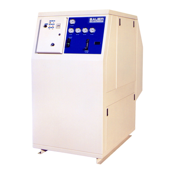
MNL- 0345 1.4 Description and Specifications 1.4.1 Unit Description The BAUER MVT26 model has an electric motor drive as the prime mover. Standard features - 6000 psig • BAUER Breathing Air Purification System • Securus Electronic Moisture Monitoring System ® •... -
Page 14: Unit Specifications
MVT26 1.4.2 Unit Specifications All specifications are subject to change without prior notice. 1.4.2.1 MVT26-E3 Medium Charging Rate 25.1 scfm Free Air Delivery 21.0 scfm Inlet pressure atmospheric Operating pressure, max. 6,000 psig Ambient temperature range 32° to 105° F Weight Approximately 6950 lb. -
Page 15: Section 2: Operations
MNL- 0345 SECTION 2: OPERATIONS 2.5 Electric Motor Driven Units The safety instructions applicable to this product are contained in Appendix A.2. They must be read, understood and complied with prior to operating the product. 2.5.1 Pre-start Checks 1. Ensure that all scheduled maintenance is completed. 2. -
Page 16: Section 3: Maintenance And Parts
MVT26 SECTION 3: MAINTENANCE AND PARTS 3.1 IK150 II and IK180 II Compressor Blocks 3.1.1 Description The IK150 II and IK180 II compressors are used to compress air up to 5000 psi. Both compressors are four cylinder, four stage air cooled, oil lubricated reciprocating compressors. The 4th stage cylinder is lubricated by means of the forced feed lubrication system, while the other cylinders are splash lubricated. -
Page 17: Component Location
MNL- 0345 3.1.1.2 Component Location Figure 3.1-2 Compressor Block (Front View) 13 (IK180II Only) 1. Service Indicator 13. 1st Stage Auxiliary Cooler (IK180II Only) 2. Intake Filter 14. 1st Stage Inter Cooler 3. Crankcase Vent Feedback Line 15. 4th Stage Cylinder 4. -
Page 18: Lubrication System
MVT26 3.1.2 Lubrication System 3.1.2.1 Description. The compressor is provided with forced-feed lubrication. The oil pressure is produced by a low revving gear pump. The oil pressure is between 44 psi and 87 psi (3 to 6 bar). CAUTION This oil pump must be operated in the correct direction of rotation, other wise no oil pressure will be built up and the compressor may be damaged. -
Page 19: Oil Level Check
MNL- 0345 3.1.2.2 Oil Level Check (See 3.1-4). Check the oil level at the oil filler sight gauge on the compressor block every day before put- ting the compressor into operation. Oil level must never be below the minimum mark molded into the sight gauge as this will cause severe damage due to lack of lubrication.Overfilling is prevented by the design of the filler neck;... -
Page 20: Venting The Oil Pump
MVT26 Figure 3.1-5 Removing the Oil Filter Cover Figure 3.1-6 Replacing the Oil Filter 3.1.2.6 Venting the Oil Pump CAUTION To avoid damage after maintenance the following measures should be strictly adhered to. (See 3.1-6). If after the start of the compressor no oil pressure builds up, venting the oil pump may be necessary, especially after maintenance and repair work. -
Page 21: Intake Filter
MNL- 0345 3.1.3 Intake Filter Figure 3.1-7 Intake Filter 1. Service Indicator 3. Filter Element 2. Cover 4. Filter Housing 3.1.3.1 Description (See 3.1-7). A dry micronic filter is used to filter intake air. 3.1.3.2 Maintenance The vacuum in the intake filter is monitored by the Service Indicator (1). When the preset vacuum pressure is reached the indicator changes to red and the Filter Element (3) should be replaced as follows. - Page 22 MVT26 Figure 3.1-8 2nd Stage Intermediate Separator Figure 3.1-9 3rd Stage Intermediate Separator WARNING Dynamic Loading The rapid depressurizing and repressurizing of an intermediate separator during condensate draining sub- jects it to metallurgical stresses. To prevent catastrophic failure with the possibility of damage, injury or death the intermediate separator must be replaced after 85,000 load cycles.
-
Page 23: Intermediate Separators
MNL- 0345 3.1.4 Intermediate Separators 3.1.4.1 Description Two intermediate separators are mounted on the compressor, one after the 2nd stage and another after 3rd stage. These separators are designed to remove oil and water which accumulates due to the cooling of the air after the compression process. -
Page 24: Compressor Valves And Valve Heads
MVT26 3.1.5 Compressor Valves and Valve Heads 3.1.5.1 Functional Description The valve heads of the individual stages form the upper part of the cylinders. The inlet and pressure valves are fitted inside the valve heads. When the piston moves downwards, the resultant vacuum in the piston cylinder opens the inlet valve. When the piston moves upwards, the inlet valve is closed and the pressure valve opened by the pressure created in the compression process. -
Page 25: Changing The 1St Stage Valves
MNL- 0345 6. Observe the correct sequence when reassembling. 7. After finishing all maintenance work on the valves, turn the compressor manually using the flywheel and check whether all items have been correctly installed. 8. 30 minutes after restarting the compressor, stop the unit, let it cool down to ambient temperature, and retighten valve studs and cap nuts. -
Page 26: Changing The 2Nd And 3Rd Stage Valves
MVT26 3.1.5.5 Changing the 2nd and 3rd Stage Valves See Figure 3.1-12 Figure 3.1-12 2nd and 3rd Stages Valve Heads and Valves 1. Hex Nut 4. Extraction Groove 7. Valve Gaskets 2. Cap Holder 5. O-Rings 8. Valve Head 3. Valve Caps 6. -
Page 27: Changing The 4Th Stage Valves
MNL- 0345 3.1.5.6 Changing the 4th Stage Valves See Figure 3.1-13 CAUTION Always change the intake and discharge valves of the 4th stage at the same time. Figure 3.1-13 4th Stage Valve and Head Figure 3.1-14 4th Stage Discharge Valve Removal 3.1.5.6.1 Discharge Valve Removal Procedure 1. -
Page 28: Inlet Valve Removal And Installation
MVT26 2. Put O-ring (4) into Valve Head (7). 3. Insert Discharge Valve (5) into Valve Head (7). 4. Put on Valve Cover (8). 5. Screw in Socket Head Screws (9) and tighten with a torque wrench to the value listed in the Appendix 6. -
Page 29: Troubleshooting
MNL- 0345 3.1.6.2 Troubleshooting Cause Remedy Trouble No oil pressure 1. Low oil level 1. Check oil level 2. Air trapped in oil pump. 2. Vent Oil Pump Oil foam in crankcase 1. Last stage piston worn 1. Operate compressor with 2. -
Page 30: Replacement Parts List
MVT26 3.1.7 Replacement Parts List Figure 3.1-17 Crankcase Assembly 31 32 Item Qty Part No. Description Notes ◊ 78577 Crankcase Assembly N20649 Screw 68586 Cover Plate N15093 O-ring 26281 Shaft Seal N370 Self Locking Hex Nut Washer 78897 Bearing Cover N3138 Stud N18303... - Page 31 MNL- 0345 Figure 3.1-17 (cont.) Crankcase Assembly Item Qty Part No. Description Notes 3177 Gasket N2638 Roller Bearing N4467 Eye Bolt 1492 Washer 79225 Hexagonal Spacer N4150 Stud 80197 Reducer N293 Gasket N314 Plug Washer N312 Hex Head Screw 78571 Bracket N4163 Gasket...
- Page 32 MVT26 Figure 3.1-18 Complete Crankshaft Assembly Item Qty Part No. Description Notes ◊ 78934 Crankshaft Assembly K150 II Only ◊ 79442 Crankshaft Assembly K180 II Only 68587 Bushing N4366 Dowel Screw N108 Spring Washer Hex Nut 4220 Spacers N18310 Circlip N423 Circlip October 2003...
- Page 33 MNL- 0345 Figure 3.1-19 K150II 1st Stage Piston and Cylinder Item Qty Part No. Description Notes ◊ 79420 1st Stage Piston and Cylinder Assembly120mm Dia 79017 Cylinder 120mm Dia N2621 O-ring N26036 Stud 79720 Piston Assembly 120 mm Dia 79719 Piston N2930 Pin, Piston...
- Page 34 MVT26 Figure 3.1-20 K180II 1st Stage Piston and Cylinder Item Qty Part No. Description Notes ◊ 79704 1st Stage Piston and Cylinder Assembly130 mm Dia 79703 Cylinder 130 mm Dia N2621 O-ring N26036 Stud 79717 Piston Assembly 130 mm Dia 79718 Piston N4109...
- Page 35 This page is inserted to provide proper page sequencing - 34 -...
- Page 36 MVT26 Figure 3.1-21 2nd Stage Piston and Cylinder Assembly October 2003 Section 3 Page 35...
- Page 37 MNL- 0345 Item Qty Part No. Description Notes ◊ 061048 2nd Stage Piston and Cylinder Assembly 60572 Cylinder N3731 O-ring N215 Stud, M8x25 WAS-0021 Washer, Flat, 8mm NUT-0019 Nut, Hex, Lock M8 070010 Compressor Piston Assembly N20907 Piston N1429 Pin, Piston N484 Ring, Retaining N1461...
- Page 38 MVT26 Figure 3.1-22 3rd Stage Piston and Cylinder Item Qty Part No. Description Notes ◊ 060107 Piston and Cylinder Assembly 67057 Cylinder Guide 60mm Dia N3731 O-ring 67061 Cylinder 32mm Dia N7063 O-ring October 2003 Section 3 Page 37...
- Page 39 MNL- 0345 Figure 3.1-22 (cont.) 3rd Stage Piston and Cylinder Item Qty Part No. Description Notes N17462 Stud M8x80 WAS-0021 Washer, Flat NUT-0019 Nut, Hex, Lock 070012 Piston, Guide Assembly 60mm Dia 60087 Piston, Guide N15409 Pin, Piston N1665 Ring, Retaining 070013 Piston, Floating Assembly N4378...
- Page 40 MVT26 Figure 3.1-23 4th Stage Piston and Cylinder Assembly Item Qty Part No. Description Notes ◊ 79180 4th Stage Cylinder Assembly 078043 Piston and Sleeve Assembly (See 3.1-24) 76754 Cylinder N7063 O-ring N370 Self Locking Hex Nut Washer N17462 Stud 79632 Guide Cylinder N3731...
- Page 41 MNL- 0345 Figure 3.1-24 4th Stage Piston and Sleeve Assembly Item Qty Part No. Description Notes ◊ 078043 Piston and Sleeve Assembly † … Piston Available only with 078043 N23755 O-ring † … Piston Sleeve Available only with 078043 N2320 O-ring †...
- Page 42 MVT26 Figure 3.1-25 K180 1st Stage Valve Head Item Qty Part No. Description Notes ◊ 79680 K180II 1st Stage Valve Head Assembly † … 1st Stage Valve Head N26029 Plate Valve Washer N644 Self Locking Hex Nut Washer N150 Allen Screw M8x60 October 2003 Section 3...
- Page 43 MNL- 0345 Figure 3.1-26 2nd Stage Valve Head Item Qty Part No. Description Notes ◊ 070026 2nd Stage Valve Head Assembly 60583 2nd Stage Valve Head SCR-0180 Socket Head Cap Screw M8x35 N4067 Valve, Inlet N4068 Valve, Discharge 56668 Gasket, Valve 56183 Cap, Valve N3997...
- Page 44 MVT26 Figure 3.1-27 3rd Stage Valve Head Assembly Item Qty Part No. Description Notes ◊ 068602 3rd Stage Valve Head Assembly 60583 3rd Stage Valve Head SCR-0180 Socket Head Cap Screw M8x35 N15273 Valve, Inlet N15274 Valve, Discharge 56668 Gasket, Valve 56183 Cap, Valve N3997...
- Page 45 MNL- 0345 Figure 3.1-28 4th Stage Valve Head Assembly Item Qty Part No. Description Notes ◊ 073629 4th Stage Valve Head Assembly 07790 Intake Valve 65191 Valve Head N2789 O-ring 014121 Discharge Valve 14118 Valve Head Cover 71065 Stud N3625 Gasket N3623 Acorn Nut...
- Page 46 MVT26 Figure 3.1-29 Flywheel Drive Assembly Item Qty Part No. Description Notes ◊ 79240 Flywheel Drive Assembly 68623 V-belt Pulley 55425 Fan Blade Support 79239 Blade, Fan CCW N19495 Hex Head Screw M6x16 WAS-0029 Washer, Split Lock 68646 Washer WAS-0002 Washer, Split Lock N15667 Hex Head Cap Screw...
- Page 47 MNL- 0345 Figure 3.1-30 Intake Filter Assembly Item Qty Part No. Description Notes ◊ 079706 Intake Filter Assembly 79679 Manifold, Air Intake N171 Socket Head Cap Screw 73036 Housing, Intake Filter 79464 Flange N19535 Allen Screw N25886 Element, Intake Filter 79465 Cover, Filter Housing N2221...
- Page 48 MVT26 Figure 3.1-31 2nd Stage Interfilter Assembly Item Qty Part No. Description Notes ◊ 077387 Interfilter Assembly † … Filter Housing Available only with 077387 † … Filter Head Available only with 077387 13937 Collar, Threaded Knurled N3556 O-ring 76613 Tube and Baffle N1316 Gasket, Cooper...
- Page 49 MNL- 0345 Figure 3.1-32 3rd Stage Interfilter Assembly Item Qty Part No. Description Notes ◊ 077388 3rd Stage Interfilter Assembly † … Filter Housing Available only with 077388 † … Filter Head Available only with 077388 13937 Collar, Threaded Knurled 12784 Plate, Vortex 12785...
- Page 50 MVT26 Figure 3.1-33 K150-180 II Cooling System Assembly Item Qty Part No. Description Notes ◊ 79626 Cooling System Assembly 79885 1st Stage Intercooler 79927 2nd Stage Intercooler 79929 3rd Stage Intercooler 79925 Aftercooler 79637 Mount 6069-M Clamp N15414 Countersunk Screw Washer N108 Lock Washer...
- Page 51 MNL- 0345 Figure 3.1-33 (cont.) IK150 II and IK180 II Cooling System Assembly Item Qty Part No. Description Notes N503 Allen Screw Hex Nut 60751 Mount N109 Allen Screw 57070 Tube Clamp 76425 Connecting Tubing 70043 Connecting Tubing 79923 Connecting Tubing 78918 Connecting Tubing 70045...
- Page 52 MVT26 Figure 3.1-33 (cont.) K150-180 II Cooling System Assembly Item Qty Part No. Description Notes N7430 Cap Screw N2003 Elbow Coupling 60709 Fan Screen 60717 Support 60716 Bracket N542 Hex Screw October 2003 Section 3 Page 51...
- Page 53 MNL- 0345 Figure 3.1-34 2nd Stage Intercooler Item Qty Part No. Description Notes ◊ 079927 2nd Stage Inter-cooler Assembly FER-0012 Ferrule NUT-0057 Nut, Tube N16310 Insert, Tube 60738 Clamp, Tube SCR-0133 Socket Head Cap Screw M6x40 WAS-0024 Washer, Flat NUT-0118 Nut, Hex Lock Page 52 Section 3...
- Page 54 MVT26 Figure 3.1-35 3rd Stage Intercooler Item Qty Part No. Description Notes ◊ 79929 3rd Stage Intercooler 60738 Clamp, Tube SCR-0133 Socket Head Cap Screw M6x40 WAS-0024 Washer, Flat NUT-0118 Nut, Hex Lock 60694-M Clamp, Tube N15119 Socket Fillister Head Screw M8x35 NUT-0062 Nut, Hex...
- Page 55 MNL- 0345 Figure 3.1-36 K180 1st Stage Auxiliary Cooler Item Qty Part No. Description Notes ◊ 076406 1st Stage Auxiliary Cooler IK180 II Only N7443 Ferrule N7435 Nut, Tube 60694-M Clamp, Tube 2-Groove N17948 Countersunk Screw M8x40 DIN7991 8.8 NUT-0119 Nut, Hex Lock M8,DIN985-8,A3A Page 54...
- Page 56 MVT26 Figure 3.1-37 Lubricating System Assembly Item Qty Part No. Description Notes ◊ 078930 Lubricating System Assembly 080345 Lubricating System See next Figure 78421 Gasket N503 Socket Head Screw 78928 Connecting Tube Assembly N20002 Connector N4501 Gasket October 2003 Section 3 Page 55...
- Page 57 MNL- 0345 Figure 3.1-38 Lubricating System 14 9 Item Qty Part No. Description Notes ◊ 080345 Lubricating System N24585 Gear Pump Washer N19506 Hex Head Screw 77885 Oil Filter Cover N25327 O-ring N3489 O-ring 77774 Rubber Gasket N25326 Filter Element N1316 Gasket 81050...
-
Page 58: Stage Automatic Condensate Drain System
MNL- 0345 3.2 4 Stage Automatic Condensate Drain System 3.2.1 Description The automatic condensate drain system operates electropneumatically and is comprised of the following: An electrically controlled solenoid valve. An electrical timer Two pneumatically operated condensate drain valves A condensate manifold A condensate separator/silencer A condensate collector bottle The automatic condensate drain system drains the intermediate separators and the oil and water separator... -
Page 59: Compressor Operating
MVT26 Figure 3.2-2 ACD Operation Diagrams Control Pressure Control Pressure Condensate Condensate Normal Operation Condensate Draining 1. Solenoid Valve 4. 3rd Stage Condensate Drain Valve 2. 2nd Stage Intermediate Separator 5. Oil and Water Separator Condensate Drain Valve 3. 3rd Stage Intermediate Separator 6. -
Page 60: Start Unloading
MNL- 0345 3.2.1.3 Start Unloading The unloading of the compressor during the starting phase is possible because of the lack of control air immediately after starting the unit. As the unit is switched on the solenoid valve (1) is energized and closes. -
Page 61: Condensate Drain Separator
MVT26 Figure 3.2-3 ACD Timer "ON" Time "OFF" Time 3.2.1.8 Condensate Drain Separator The condensate drainage is a mixture of oil, water and air. The Condensate Drain Separator is utilized to separate the oil and water from the air. The oil and water is then piped to the Condensate Collector Bottle where the oil and water mixture is stored until it can be disposed of properly. -
Page 62: Replacement Parts List
MNL- 0345 3.2.2 Replacement Parts List Figure 3.2-4 4 Stage ACD System Item Qty Part No. Description Notes ◊ 063761 Automatic Condensate Drain System 064007 Manifold N16382 Solenoid Valve 064009 Condensate Drain Valve 064008 Condensate Drain Valve N293 Gasket N9155 Reducer Page 62 Section 3... - Page 63 MVT26 Figure 3.2-5 ACD Manifold and Valves Item Qty Part No. Description Notes 064009 Condensate Drain Valve 064008 Condensate Drain Valve 064007 Manifold 064004 Valve Connection N2320 O-ring N3625 Gasket N829 Allen Screw N2507 O-ring N638 O-ring 071224 Connecting Tube N20305 Male Elbow SCR-0133...
- Page 64 MNL- 0345 Figure 3.2-6 3rd Stage Condensate Drain Valve Item Qty Part No. Description Notes ◊ 064009 Condensate Drain Valve 064000 Top Flange N16269 Sealing Ring 064003 Piston N638 O-ring N4881 O-ring 064001 Valve Body Page 64 Section 3 Base Edition...
- Page 65 MVT26 Figure 3.2-6 (cont.) 3rd Stage Condensate Drain Valve Item Qty Part No. Description Notes N2507 O-ring 064005 Valve Seat N4496 O-ring 064002 Base Flange 064498 Drain Tap Seat 065500 Drain Tap Assembly N16334 Male Tee N15088 Hose SCR-0150 Allen Screw 067458 Tool Set for Item 12 October 2003...
- Page 66 MNL- 0345 Figure 3.2-7 Oil and Water Separator Condensate Drain Valve Item Qty Part No. Description Notes ◊ 064008 Condensate Drain Valve 64000 Top Flange 064011 Spring N16269 Sealing Ring 064003 Piston N638 O-ring N4881 O-ring Page 66 Section 3 Base Edition...
- Page 67 MVT26 Figure 3.2-7 (cont.) Oil and Water Separator Condensate Drain Valve Parts List Item Qty Part No. Description Notes 064001 Valve Body N2507 O-ring 064005 Valve Seat N4496 O-ring 064002 Base Flange 064498 Drain Tap Seat 065500 Drain Tap Assembly N16334 Male Tee N15088...
-
Page 68: Trouble Shooting
MNL- 0345 3.2.3 Trouble shooting Trouble Cause Remedy Solenoid Valve does not drain. 1. Solenoid valve receives no 1. Check connections, timer. electrical signal Replace if necessary. 2. Plunger of drain valve 2. Clean or replace valve. sticking Condensate Drain Valve does not 1. -
Page 69: Section 4: Scheduling Maintenance
MVT26 SECTION 4: SCHEDULING MAINTENANCE 4.1 Maintenance Schedules WARNING Refer to the Operating and Safety Precautions in the Appendices and take all appropriate safety measures before starting any maintenance work. 4.1.1 Initial start-up or after maintenance Interval Task 1⁄2 hour after start up for the first time or after Manual check of valve function. -
Page 70: Operating Hours
MNL- 0345 4.1.3 Operating hours Interval Task 500 operating hours Check V-belts Service micronic intake filter Check all connections for leakage 1000 operating hours Manual check of valve function. Clean sintered metal filter elements in interfilters 2000 operating hours Synthetic oil change Replace valves 3000 operating hours or as required Check pistons and piston rings... -
Page 71: Maintenance Records
MVT26 4.1.4 Maintenance Records We recommend that all maintenance work be recorded in a service book, showing the date and details of the work carried out. This will help to avoid expensive repairs caused by missed maintenance work. If it is necessary to make a claim against the warranty, it will help to have proof that regular maintenance has been carried out and that the damage has not been caused by insufficient maintenance. -
Page 72: Section 4: Purification Systems
MNL- 0345 SECTION 4: PURIFICATION SYSTEMS 4.1 General The purpose of all BAUER breathing air purification systems is to remove oil, water, taste and odor from the compressed air stream before final delivery. For this reason BAUER purification systems are installed immediately before the compressed air delivery point. -
Page 73: Chamber Safety Bore
The model number, date of manufacture and serial number can be found of the compressor unit identifi- cation plate on the compressor unit’s frame. Figure 4.1-2 Compressor Unit Identification Plate BAUER BAUER COMPRESSORS, INC. COMPRESSORS NORFOLK, VIRGINIA U.S.A MODEL NO. - Page 74 MNL- 0345 Figure 4.1-3 Purification System Dataplate (typical) BAUER PURIFICATION COMPRESSORS SYSTEM MODEL NO. psig MAX. PRESSURE cu. ft. AIR PROCESSED O-RING BACK-UP RING LBL- 4.1.5.3 Cartridge Installation Dataplate The function performed by each chamber in the purification system is determined by the type of cartridge installed in that chamber.
- Page 75 MVT26 The ambient air temperature and its ability to cool the compressor will effect the operating life of the car- tridge. See Paragraph 4.1.6.2 for the method of calculating this adjustment factor. The optimum place to measure the temperature is at the inlet to the final separator as this best reflects the temperature of the air as it enters the chambers.
- Page 76 MNL- 0345 Figure 4.1-5 Correction Factor for Cartridge Operating Hours Temperature Temperature Correction Correction Factor Factor ˚F ˚F ˚C ˚C 3.80 3.80 2.62 2.62 1.85 1.85 1.34 1.34 1.00 1.00 0.75 0.75 0.57 0.57 0.43 0.43 0.34 0.34 ˚F ˚F ˚C ˚C Figure 4.1-6 Example Record of Adjusted Operating Hours...
- Page 77 MVT26 4.1.7 Air Purification Cartridge Operating Hours Date Operating Ambient temp. Correction Adjusted cartridge hours hours during compression factor Today Total October 2003 Section 4 Page 77...
- Page 78 MNL- 0345 P5 Purification System 4.2.1 Component Description The P5Purification System major components are a Coalescing Oil and Water Separator, a Dryer Cham- ber and a Purification Chamber. Figure 4.2-1 shows the functional interconnection of all the components. TheP2 purification system is available with the Securus Moisture Monitoring System as a factory ®...
- Page 79 MVT26 4.2.1.2 Cartridge 4.2.1.2.1 Cartridge Construction The casing, top and bottom of all cartridges are aluminum and are packed with one or more of the follow- ing ingredients. 1. A catalyst to convert carbon monoxide to carbon dioxide. 2. Activated carbon which absorbs oil vapors effecting taste and odor. 3.
- Page 80 MNL- 0345 4.2.1.8 Safety Valve The safety valve is located on the coalescing oil and water separator and acts as the safety valve for the final stage of the compressor. 4.2.1.9 Securus Electronic Air Purification Monitoring System ♦ The Securus Electronic Air Purification Monitoring System is a factory installed option which warns the ♦...
- Page 81 MVT26 3. Remove the tubes connected to the side of the filter head (1). 4. Unscrew and remove the filter head. 5. Unscrew the sintered metal filter (2) from the filter head. 6. Remove the center screw (3) to remove the sintered metal filter. 7.
- Page 82 MNL- 0345 4.2.2.2 Cartridge Replacement To change the cartridge, proceed as follows. See Figure 4.2-3 Figure 4.2-3 Cartridge Replacement 1. Disconnect the power and shut off the inlet supply line, if applicable. 2. Depressurize the system by means of the bleed valve. 3.
- Page 83 MVT26 4.2.3 Replacement Parts List Figure 4.2-4 Oil and Water Separator Item Qty Part No. Description Notes ◊ 079416 Oil/Water Separator Assembly † … Separator Head Available only with 079416 N04736 Backup Ring 061860 Sintered Metal Filter † … Separator Housing Available only with 079416 †...
- Page 84 MNL- 0345 Figure 4.2-5 27” Chamber Assembly Item Qty Part No. Description Notes ◊ 80144 Chamber Assembly 27” 012293 Tool Post Screw 061237 Cover Plate † 80147 Filter Head Available only with 80144 N04736 Back-up Ring N04735 O-ring † 80158 Filter Housing Available only with 80144 †...
- Page 85 This page is inserted to provide proper page sequencing - 85 -...
- Page 86 MNL- 0345 Figure 4.2-6 Securus Electronic Air Purification Monitoring System ♦ The Securus Air Purification Monitoring System is a Factory Installed Option which may not apply to your equipment Item Qty Part No. Description Notes ◊ 80145 Securus Chamber Assembly 27”...
- Page 87 MVT26 Figure 4.2-6 (cont.) Securus Air Purification Monitoring System ♦ Item Qty Part No. Description Notes 059852 Drawback Screw 059854 Loose Pin 060062 Compression Spring 059853 Fixed Pin 059851 Bolt 002181 Compression Spring N15095 Securus Indicator 110 - 120VAC, 50 - 60 Hz ♦...
- Page 88 MNL- 0345 SECTION 5: COMPRESSOR UNIT DRIVE 5.1 Vertical Compressor Drive The compressor is driven by the drive motor through a V-belt. The direction of rotation, as seen facing the flywheel, is counterclockwise. Observe the arrow on the compressor block. Check the V-belt regu- larly for damage and wear.
- Page 89 MVT26 5.1.1 Maintenance of the V-belt and Sheaves 5.1.1.1 Check The Sheaves. Before a new set of drive belts are installed, the condition of the sheaves should be checked. Dirty or rusty sheaves impair the drive’s efficiency and abrade the cover of the belts, which results in premature failure.
- Page 90 MNL- 0345 SECTION 6: MISCELLANEOUS 6.1 Pneumatic Valves and Controls 6.1.1 Nonadjustable Valves The condensate drain valve, bleed valve and check valves are not adjustable. The condensate drain valve and bleed valve have seats and seals which should be replaced if the valve leaks. Check valves are not adjustable or repairable and must be replaced if they malfunction.
- Page 91 MVT26 6.1.3 Safety Valves Figure 6.1-2 Safety Valves The safety valve must be checked periodically for proper functioning. 1. Operate the compressor with the shut-off valve closed until the safety valve vents. 2. Note the pressure registered on the pressure gauge. The safety valve is adjusted at the factory to the required pressure and does not normally require mainte- nance or readjustment.
- Page 92 MNL- 0345 6.2 Electrical Controls and Indicators 6.2.1 Pressure Switch The automatic switching of the compressor unit off and on is governed by the final pressure switch. The value of this switch is adjustable. The approximate actuation value (differential) of the final pressure switch is fixed at whatever pressure setting is required for proper operation of the unit.
- Page 93 MVT26 Wire Code Lead Color Normally Closed Blue Common Purple Normally Open 6.2.1.2 Indicators This compressor unit is equipped with an Hourmeter to record the number of hours the unit has been operated. It is also equipped with one or more of the following pressure indicators. Intermediate Pressure Gauges- Indicate the pressure between compression stages.
- Page 94 MNL- 0345 6.2.1.3 Replacement Parts List 6.2.1.3.1 Electrical Parts Figure 6.2-2 Electrical Parts Item Qty Part No. Description Notes SWT-0160 Pressure Switch 7500 psi SWT-0220 2 Position Selector Switch Illuminated, Green SWT-0119 Pressure Switch 360 - 1700 psi LIT-0082 Light Green —...
- Page 95 MVT26 6.2.1.3.2 Indicators Figure 6.2-3 Indicators Item Qty Part No. Description Notes HMR-0021 Hourmeter GAG-0006W 2.5” Indicator 200 psi — GAG-0007W 2.5” Indicator 600 psi — GAG-0008W 2.5” Indicator 1500 psi — GAG-0009W 2.5” Indicator 7500 psi October 2003 Section 6 Page 95...
- Page 96 MNL- 0345 SECTION A:APPENDICES A.1 Reference Data A.1.1 Tightening Torque Values 1. Unless otherwise specified in text, the torque values in Table 1 apply. 2. The indicated torque values are valid for bolts in greased condition. 3. Self locking nuts must be replaced on reassembly 4.
- Page 97 MVT26 A.1.4 Approved Lubricants Chart Unless otherwise specified in text, use the lubricants in Table 2. Usage Lubricants O-rings, rubber and plastic parts; filter housing Parker Super “O” Lube threads, sealing rings Bolts, nuts, studs, valve parts, copper gaskets and Never-Seez NSWT, Pipe Dope or teflon tape tube connection parts (threads, cap nut and com- pression rings)
- Page 98 MNL- 0345 A.2 Safety A.2.1 General Safety Precautions • Read the operating manual before installing or operating this compressor unit. Follow appropriate handling, operation and maintenance procedures from the very beginning. The maintenance schedule contains measures required to keep this compressor unit in good condition. Maintenance is simple, but must be executed regularly to achieve safe operation, maximum efficiency and long service life.
- Page 99 Bauer Compressors, Inc. The purchaser is urged to include the above provision in any agreement for resale of this compressor.
- Page 100 MNL- 0345 A.2.2 Safety Warning Labels Notes, labels and warning signs are displayed on the compressor unit according to model, application or equipment and may include any of the following. HOT SURFACES DO NOT TOUCH! Danger of burning if cylinders, cylinder heads, or pressure lines of individual compressor stages are touched.
- Page 101 MVT26 A.3 Long Term Storage A.3.1 General If the compressor unit will be out of service for more than six months, it should be preserved in accor- dance with the following instructions: 1. Make sure that the compressor is kept indoors in a dry, dust-free room. 2.
- Page 102 MNL- 0345 3. Shut down the compressor. 4. Open the condensate drain valves, depressurize the unit, then close the drain valves again. 5. Remove the intake filter and replace the dust cap on the inlet port. A.3.5 Lubrication Oils for Preservation 1.
- Page 103 MVT26 A.4 Unpacking, Handling and Installation A.4.1 Unpacking and Handling This compressor unit is packaged according to the requirements for shipping via the requested type of carrier service. It is possible that the compressor unit could have been damaged during shipping. For this reason, we urge you to thoroughly examine the unit for possible damage and report any such damage to the shipping company immediately.
- Page 104 MNL- 0345 CAUTION The inclination values listed in Paragraph 1.4 are valid only if the oil level of the compressor is level with but does not exceed the upper mark of the oil dipstick or oil level sight glass Ensure that the compressor air intake is supplied with fresh air. The intake air must not contain any exhaust fumes or flammable vapors such as paint solvents, which may cause an internal fire.
- Page 105 MVT26 Natural ventilation should only be used up to a maximum drive power of 20 hp. To determine the size of the required intake and exhaust openings, refer to the following table: . Intake and Exhaust Openings Dependent on Room Volume (V) and Height (h) V = 1750 ft³...
- Page 106 MNL- 0345 A.4.2.3 Electrical Installation A.4.2.3.1 Electric Drive When making the electrical connections to the system, the following instructions are mandatory: • Comply with all local, state and federal regulations concerning electrical installation. • Arrange for the electrical connections to be made by a certified electrician only. •...
- Page 107 MVT26 3 PHASE Motor Full Load Amps Fuse Amps Minimum Wire Size 208V 230V 460V 208V 230V 460V 208V 230V 460V 10.6 17.5 16.7 15.2 24.2 17.5 30.8 46.2 59.4 74.8 211.2 343.2 2-4/0 2-3/0 2-300 2-4/0 Dual element time delay fuse amps. Normal copper wire with THW, THWN or XHHW insulation.
- Page 108 MNL- 0345 A.5 Reproducible Forms A.5.1 Scheduled Maintenance Form Daily Para. Date Signature Page 108 Section A Base Edition...
- Page 109 MVT26 Weekly or as required. Para. Date Signature 500 Operating Hours. Para. Date Signature 1,000 Operating Hours. Para. Date Signature 2,000 Operating Hours. Para. Date Signature October 2003 Section A Page 109...
- Page 110 MNL- 0345 3,000 Operating Hours. Para. Date Signature Annually. Para. Date Signature Biennially. (Every two years) Para. Date Signature Page 110 Section A Base Edition...
- Page 111 MVT26 A.5.2 Record of Operating Hours Date Minutes Total Date Minutes Total Subtotal: Subtotal: October 2003 Section A Page 111...
- Page 112 MNL- 0345 A.5.3 Purifier Cartridge Adjusted Operating Hours. Date Operating Ambient temp. Correction Adjusted cartridge hours hours during compression factor Today Total Page 112 Section A Base Edition...
- Page 113 MVT26 A.6 Additional Documents A.6.1 Diagrams and Drawings Any included drawings, wiring diagrams, pneumatic flow diagrams, etc., will be bound next to the back cover in a hardcopy manual or included as a separate file on a CD. A.6.2 Other Documents OEM Manuals and other BAUER manuals may be included in the documentation shipping package.
Need help?
Do you have a question about the MAXI VERTICUS and is the answer not in the manual?
Questions and answers