
Subscribe to Our Youtube Channel
Related Manuals for Magnetic Autocontrol MPR 112


Summary of Contents for Magnetic Autocontrol MPR 112
- Page 1 Operation and Installation Instruction Retractable Flap Barrier Model MPR 112 page 1/72 www.MagneticPedestrian.com | (800) 878-7829 | Sales@MagneticPedestrian.com...
-
Page 2: Table Of Contents
Table of Contents Delivery........................4 Scope of delivery......................4 Technical data ......................4 Code table ........................5 Lane configuration......................6 Safety........................7 General safety notes ....................7 Intended use......................... 7 Warnings and symbols used in this manual..............8 Safety notes ......................... 9 Product Description .................... - Page 3 Maintenance......................62 10.5. Wing replacement...................... 62 10.6. Motor replacement..................... 64 10.7. Software up date ....................... 65 Technical Support ....................68 Spare Parts and Accessories ................68 Warranty ....................... 68 Disposal........................ 69 List of figures....................... 71 581E,5721/ 07/2006 MPR112_1 page 3/72 Version: 01...
-
Page 4: Delivery
Delivery Delivery Scope of delivery 1 x Retractable barrier (quantity and models depend on lane layout) 4 x Mounting hardware 2 x Keys 1 x Documentation 1.2 Technical data MODEL Dimens. TECHNICAL DATA unit MPR-112A/B-A2X0 MPR-112A/B-A3X1 MPR-112A/B-A2X2 Voltage 115-240 115-240 115-240 Frequency 50-60... -
Page 5: Code Table
Delivery Code table M P R - 1 1 2 A - A 1 0 0 - XXXXX Options Customer or project code Housing 0 = Narrow (200mm) passage 520 / 50mm gap 1 = Middle (250mm) passage 520 / 50mm gap 2 = Wide (280mm) passage 960 / 50mm gap 3 = Narrow (200mm) passage 550 / 50mm gap 4 = Narrow (200mm) passage 600 / 50mm gap... -
Page 6: Lane Configuration
Delivery 1.4 Lane configuration A /D / F Module - no controller B Module - one controller C / E Module - two controllers ● MBC Lane controller Combination is valid for the following housing widths: 200 mm 250 mm 280 mm Lanes Combination is valid for... -
Page 7: Safety
Safety Safety General safety notes The MPR (MAGNETIC Pedestrian Retractable Barrier) has been designed, built, and tested according to the latest available technol- ogy. The product has left the factory in a fully operational and safe condition. However, it is imperative that the installation is carried out in accordance to this operating manual. -
Page 8: Warnings And Symbols Used In This Manual
Safety Warnings and symbols used in this manual The following symbols and references are used in this manual to give instructions and warnings (cautions) of particular importance. These must always be strictly observed! Purchased components may have additional specific warnings that also need to be strictly observed. -
Page 9: Safety Notes
Safety RECYCLING! When disposing of the unit at the end of utilisation ensure those noxious and dangerous residues are disposed of in accordance with the regulations. Based on the different material, disposal must occur in a separate manner. The used lubrication and auxiliary material such as oils and fats will be disposed of in accordance with the statutory provisions. -
Page 10: Product Description
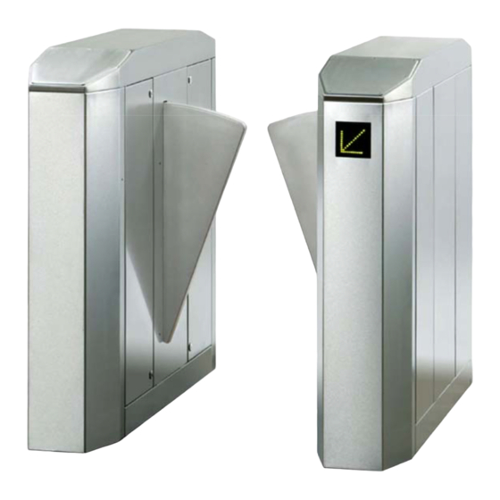
Product Description Product Description 3.1 General The MPR retractable barrier is a user friendly access control barrier designed for rapid pedestrian entrance and exits to and from train stations, corporate receptions, airport terminals, immigration facili- ties, sports stadiums, etc. The modular design allows a multitude of different lane and design configurations. -
Page 11: Static Stability Test
Product Description Static stability test To show the stability of the wing into the mounted housing, Magnetic made a few different tests, to demonstrate and determine the stability of the wing. Static test Impact Pendulum test Dynamic front Impact test 3.3.1 Static test The simulation shows the stability of the wing for static acting... - Page 12 Product Description 3.3.2 Impact pendulum test With the Pendulum test we simulate a dynamic side impact. This can occur in case of vandalism. ( kick against the wing ) For testing, the pendulum was loaded with different weights at its end.
- Page 13 Product Description Fig. 3-3 Detail pendulum impact test; figure shows a deformation of 0.5 mm at an impact force of 1000 N 3.3.3 Dynamic front impact test This test demonstrates the dynamic impact force of the wing during operation (closing). The tests are determined according to the gate standard DIN EN 12453 with the prescribed measuring instrument .
- Page 14 Product Description Fig. 3-4 Dynamic test; impact force of wing at status 1/2 extended on the load cell (soft flap shown) 3.3.4 Overview closing times Housing type Wing material Speed Acrylic-wing approx. 350 ms PUR- wing approx. 300 ms Telescopic approx.
-
Page 15: Housings And Lane Widths
Product Description 3.4 Housings and lane widths The MPR is offered in three different housings and lane widths with different types of flaps and flap materials. The available housing widths are 200 mm, 250 mm and 280 mm. The standard lane widths 900 mm are 520 mm or 960 respectively 990 mm (depending on the distance for us also... - Page 16 Product Description Definition of passage (DG): Note! The passage width (DG) is calculated as follows: DG = (2 x extended flap width) + (50 mm flap gap) Right, Module A Module B Short ← → distance Left, long ← → distance Fig.
-
Page 17: Mounting And Installation
Mounting and installation Mounting and installation 4.1 Foundation The mounting surface of the concrete-foundation must be level to insure a solid base for the MPR. Once the concrete has set to an adequate hardness, the holes for the anchor bolts can be drilled us- ing the dimensions shown in Fig. - Page 18 Mounting and installation • MBC Lane Controller Housing width: 200 mm A = 1400 mm B = 250 mm C = DG + 200 mm Housing width: 250 mm A = 1400 mm B = 300 mm C = 770 mm Housing width: 280 mm A = 1400 mm B = 330 mm...
- Page 19 Mounting and installation • MBC Lane Controller Housing widths: 200 mm and 280 mm A = 1400 mm B = 250 mm C = DG + 200 mm D = DG + 240 mm E = DG + 280 mm •...
-
Page 20: Access Doors
Mounting and installation 4.2 Access Doors The motor as well as the drive- and control units are located behind the hinged housing doors. Access is granted to authorized people by using the key supplied with the retractable barrier. Fig. 4-4 Access to drive unit and controller 581E,5721/ 07/2006 MPR112_1 page 20/72... -
Page 21: Mounting
Mounting and installation Mounting Please follow the schematic Fig. 4-5 for proper installation. Please make use of the mounting hardware included in the delivery. Conduits Fig. 4-5 MPR mounting with U-profile 1 – MPR housing 2 – concrete fundament 3 – nut, split washer, plain washer 4 –... -
Page 22: Electrical Connection
Electrical Connection Electrical Connection 5.1 Overview CAUTION! The connection of the electrical mains may be accomplished only by an electrical specialist! Fig. 5-1 Electrical Connection B1 = safety PE-beam right B2 = safety PE-beam left B3 = outside right B4 = outside left 581E,5721/ 07/2006 MPR112_1 page 22/72 Version: 01... - Page 23 Electrical Connection Entrance (Secured zone) Display left Safety Rx B4 Safety Rx B2/B6 Rx B1/B5 Safety Safety Rx B3 Display right Exit (None secured zone) Fig. 5-2 Electrical Connection, top view 581E,5721/ 07/2006 MPR112_1 page 23/72 Version: 01...
-
Page 24: Wiring Diagrams
Electrical Connection 5.2 Wiring diagrams Fig. 5-3 Wiring diagram 1 581E,5721/ 07/2006 MPR112_1 page 24/72 Version: 01... - Page 25 Electrical Connection Fig. 5-4 Wiring diagram 2 581E,5721/ 07/2006 MPR112_1 page 25/72 Version: 01...
-
Page 26: Access Control Devices
Access Control Devices Access Control Devices When installing access control devices the following measures for mounting has to be considered. Maximum allowed dimensions Maximum depth for instal- for access control device lation Fig. 6-1 Mounting instructions for access control device 581E,5721/ 07/2006 MPR112_1 page 26/72 Version: 01... -
Page 27: Commissioning
Commissioning Commissioning 7.1 General After the mechanical and electrical installation of the gate it can be set in operation. Before starting the system it has to be checked that all mechanical work as well as electrical installation has to be car- ried through correctly. -
Page 28: Start- Up Instructions
Commissioning 7.2 Start- Up instructions With the help of the steps specified in the brief instruction a fast start-up of the unit can take place. The points for wiring described below have to be accomplished with the first installation before the start-up of the MPR. Find the details to the appropriate points indicated in the cross ref- erences. -
Page 29: Functional Description Of Mbc110
Functional description of MBC110 Functional description of MBC110 8.1 Inputs and Outputs The program is applied to controllers of the series MBC-110B-Fxxx. The hardware components described below are available. 8.1.1 Hardware of Inputs The inputs 1 to 7 are optical isolated by opto-couplers. They are connected to one plug-in connector. - Page 30 Functional description of MBC110 8.1.2 Hardware relay outputs The relay outputs 1 to 6 are connected to one plug-in connector. Several groups are summarized in order to economize connecting terminals. Fig. 8-2 Connection of relay outputs, simplified diagram 581E,5721/ 07/2006 MPR112_1 page 30/72 Version: 01...
-
Page 31: Additional Internal Inputs And Outputs
Functional description of MBC110 Additional internal inputs and outputs 8.2.1 Hardware of the internal inputs and outputs The additional inputs and outputs are not needed in each mode of operation. They can be used also for special functions. The outputs are MOSFET drivers, the inputs are opto isolated. The in-puts are on one side on the internal GND potential and thus may not be led out from the housing of the barrier;... - Page 32 Functional description of MBC110 8.2.2 Default input functions Input 1 is not alterable because the input is connected with the ASB input of the servo output stages Inputs 2 and 9 are alterable with other functions by parameters. Input Default / Factory settings Input 1 Emergency Input 2...
- Page 33 Functional description of MBC110 Input 4 = Clearance Mode Determine the use direction of the gate. IN 4 IN 5 Clearance Mode Out of service = wings closed Entry Mode = passage only from entry / left Exit Mode = passage only from exit/ right Bi-directional Mode = passage from both directions 1 = active;...
- Page 34 Functional description of MBC110 8.2.3 Default function of outputs The function of relay 1 is not alterable because this output is also used as feedback for power supply loss. Output Default function Relay 1 Global alarm output / Voltage failure Relay 2 Ready for passage left Relay 3...
- Page 35 Functional description of MBC110 NOTE! In that a wire break is to be indicated at the global alarm output, re- lay 1 is inverted operated. That means that the relay is energized as long as no error is present. As soon as one of the described errors appears the relay will be switched off.
- Page 36 Functional description of MBC110 Output 1 = Gate End Display left red This output controls the red cross at left GED. Output 2 = Gate End Display left green This output controls the green arrow at left GED. Output 3 = Gate End Display right red This output controls the red cross at right GED.
- Page 37 Functional description of MBC110 Display of error codes First the character “E“ (error) is displayed followed by the first num- ber of the error code, the second number of the error code (plus dot) and at last an interval. After that the cycle starts again. Each status is displayed for 2 seconds.
-
Page 38: Parameter Settings
Functional description of MBC110 Error codes with automatic reset function will be displayed for fur- ther 10 seconds after the error is rectified. But as long as the error exists as long the error code is displayed. All other errors will cause pedestrian barriers to be set out of opera- tion. - Page 39 Functional description of MBC110 A short beep is also sent out in following situations: • If the gate is ready for passage • After a passage has been completed DIP 2 Buzzer Buzzer off Buzzer on 8.3.3 DIP- switch 3 and 4: Safety delay time It is the additional time after receiving the closed command.
- Page 40 Functional description of MBC110 DIP 7 Update Version Software Operating mode display Update Version displayed 8.3.6 DIP- switch 8: Reserved Reserved for future applications. DIP 8 Reserved Not used Not used 8.3.7 DIP- switch 9 and 10: Program - Mode By selecting the program mode it is determined which control pro- gram starts after power on and reset.
- Page 41 Functional description of MBC110 8.3.9 DIP- switch 12: Behaviour after impact detection Determines the behaviour after an impact detection. DIP 12 Behaviour after impact detection Wings are still trying to close (no retract) Wings open immediately and try to close with reduced speed 8.3.10 DIP- switch 13: Reverse during closing After receiving the close signal the wings try to close.
- Page 42 Functional description of MBC110 8.3.12 DIP- switch 16: Reserved For future applications DIP 16 Reserve Not used Not used Hold-Open time The hold-open time is displayed as countdown in 1 s steps. If the rest hold open time is above 9 s the display shows a special charac- ter or “F”...
-
Page 43: Description Mode 2
Functional description of MBC110 8.4 Description Mode 2 Mode 2 allows free entry or exit in both directions. This requires the installation of two PE beams at the end of the barriers close to the card readers (standard). The two light beams can have two functions. First it allows free entry or exit by opening the flaps when a person comes from the correct direction, and secondly it allows the controller to detect persons coming from an incorrect direction, hence the barrier remains... - Page 44 Functional description of MBC110 8.4.1 Mode 2: Emergency Mode The emergency input IN1 supersedes any other input. The emer- gency input is NORMALLY CLOSED; if this signal is open, the bar- rier opens immediately overriding any other existing and ignoring following inputs.
- Page 45 Functional description of MBC110 Direction right (exit): Barrier End Display shows RED CROSS Opening input Right disabled Output r.f.p.r. is off Output l.c.r.r. is set While the Out-of-Service mode is activated the controller activates an alarm output every time a person walks into the light beams on each end of the gate 8.4.3 Mode 2: Entry Mode...
- Page 46 Functional description of MBC110 8.4.4 Mode 2: Exit Mode If IN5 is activated (contact closed) and IN4 disabled (contact open) the barrier allows passage only from right to left (exit). Any opening inputs on IN 4 are ignored. Direction left (entry): Barrier End Display shows GREEN ARROW Opening input Left is activated Directional beams are active and evaluated based on the walk-...
- Page 47 Functional description of MBC110 8.4.5 Mode 2: Bidirectional Mode If both, IN4 and IN5 is activated (contact closed) the barrier allows passage from both directions. Direction left (entry): Barrier End Display shows GREEN ARROW Opening input Left is activated Directional beams are active and evaluated based on the walk- through direction r.f.p.l.
- Page 48 Functional description of MBC110 8.4.6 Mode 2: Free Entry Mode To activate the free entry mode, IN4 must be activated (contact closed), IN5 must be disabled (contact open) and IN2 must be per- manently activated (contact closed). Any access control opening pulses on IN3 are ignored.
- Page 49 Functional description of MBC110 8.4.7 Mode 2: Free Exit Mode To activate the free exit mode, IN5 must be activated (contact closed), IN4 must be disabled (contact open) and IN3 must be per- manently activated (contact closed). Any access control opening pulses on IN2 are ignored.
- Page 50 Functional description of MBC110 8.4.8 Mode 2: Free Entry, Controlled Exit Mode If IN4 and IN5 are active and the opening signal at IN2 is maintained the barrier is set-up for free entry (right) and controlled exit (left) through an access control device. The barrier is always closed and opens as soon as a person enters the lane from the “free direction”...
- Page 51 Functional description of MBC110 8.4.9 Mode 2: Controlled Entry, Free Exit Mode If IN4 and IN5 are active and the opening signal at IN3 is maintained the barrier is setup for free exit (right) and controlled entry (left) through an access control device. The barrier is always closed and opens as soon as a person enters the lane from the “free direction”...
- Page 52 Functional description of MBC110 8.4.10 Mode 2: Fully Free Mode To setup the barrier to “free mode” in both directions, the signal on IN2, IN3, IN4, and IN5 must be maintained. The barrier remains open at all times. No directional logic is acti- vated.
- Page 53 Functional description of MBC110 opening input erases. In applications, using cons or tokens to allow entry or exit the token or coin is lost. The barrier will close immediately after the patron passes through both, safety beams and the “hold open timer” is erased. The controller provides a feature called “safety delay timer”.
-
Page 54: Mode 2: Homing - Teach-In Procedure
Functional description of MBC110 After recording a mode change no new opening impulses are ac- cepted. That means both opening entries must be ignored and both card readers must be locked. 8.4.13 Mode 2: Homing – Teach-in procedure Both end positions are taught-in, i.e. a homing is realised. For this after return of tension the motor firstly goes to the inner rub- ber buffer and so determines the open end position. - Page 55 Functional description of MBC110 8.5.2. Breakthrough attempts Depending on the adjusted force the wings are blocked in the final position (levers in neutral) or they can be pushed open by a certain force in opening direction. 8.5.3. Emergency Situation If during operation the emergency input is being activated the barrier goes immediately into safe mode.
-
Page 56: Mbc110 Circuit Diagrams
Functional description of MBC110 8.6. MBC110 circuit diagrams Fig. 8-4 MBC Connection diagram 581E,5721/ 07/2006 MPR112_1 page 56/72 Version: 01... - Page 57 Functional description of MBC110 Fig. 8-5 Logic Module MBC 110 581E,5721/ 07/2006 MPR112_1 page 57/72 Version: 01...
-
Page 58: Mmc-120 Controller
MMC-120 Controller MMC-120 Controller The MMC controller has been wired and adjusted und left the fac- tory in a fully operational condition. Other adjustments are not pos- sible by default. The DIP switches are for scheduling the CAN Bus and cannot be changed. Conversions and modifications to the control module are not permit- ted. - Page 59 MMC-120 Controller DIP switch (J1) / right: S1 - OFF S2 - OFF S3 - OFF S4 - OFF Fig. 9-2 MMC 120 Controller – right side, schema and DIP switch setting (J1) 581E,5721/ 07/2006 MPR112_1 page 59/72 Version: 01...
- Page 60 MMC-120 Controller Fig. 9-3 Wiring diagram, power supply unit and PE beams 581E,5721/ 07/2006 MPR112_1 page 60/72 Version: 01...
-
Page 61: Safety Pe-Beam System
Safety PE-Beam System 10. Safety PE-Beam System All safety beams are setup in fail-safe mode; hence, the PNP- Output is switched on during normal operation and switched off when an object is detected. In addition, each light beam is monitored for proper operation. Meaning that if a light beam shows detection for longer than 30 sec- onds the controller assumes that the light beam is malfunctioning (e.g. -
Page 62: Maintenance
Maintenance Maintenance 10.5. Wing replacement Dismounting the wing CAUTION! Before starting any kind of maintenance work make sure that the main power supply is switched OFF! If it is necessary to replace a wing proceed stepwise as follows: Open the service door at the housing; refer to chapter 4.2 “Access Doors”... - Page 63 Maintenance Loosen the socket head screw of the lever on the motor drive shaft Remove the socket head screw of the fixing between lever and wing Pull off the levers from the motor drive shaft. Remove the pivot point bolt of the wing bearing Take out the wing backwards.
-
Page 64: Motor Replacement
Maintenance 10.6. Motor replacement CAUTION! Before starting any kind of maintenance work make sure that the main power supply is switched OFF! If it is necessary to replace the MHTM (MAGNETIC High Torque Motor) proceed stepwise as follows: Open the service door at the housing; refer to chapter 4.2 “Access Doors”... -
Page 65: Software Up Date
Maintenance NOTE! The resolver unit is adapted to the motor. The resolver cannot be replaced separately but only as complete unit due to special cali- bration! For fitting the new motor proceed in opposite sequence. When start- ing the system after motor replacement the mechanic system is calibrated automatically by the resolver. - Page 66 Maintenance How to download the Software 1. First Step is to open the down load the latest Software version to the MBC controller. This has to be done by using the M16C Flasher Software. Steps . Select the COM Port 2.
- Page 67 Maintenance 2. Second step is to download the servo program from the MBC to the two MMC servo controllers. To start the download, the following steps are necessary. a) Write down the DIP switch setting as it is.( so you can restore the original setting after download) b) Set all 16 DIP switches to position ON c) Turn the power OFF, wait min.
-
Page 68: Technical Support
Technical Support 10. Technical Support In case of problems please contact an authorized after sales service representative. NOTE! Please refer to the nameplate of the MPR Kit Set for the data re- quired in the case of inquiries. 11. Spare Parts and Accessories An exploded drawing with details of the individual parts and their identification numbers is available on demand. -
Page 69: Disposal
Disposal 12. Disposal CAUTION! All applicable regional regulations, rules and laws relevant to the disposal of materials and machinery must be strictly followed. Packing material Once the equipment has been unpacked the packing materials have to be separated into the different basic materials (wood, cardboard, plastics, etc.) and then disposed in an expert manner. - Page 70 Disposal Environment In order to prevent environment pollution we recommend a careful separation and disposal of all materials. RECYCLING! When disposing of the unit at the end of utilisation ensure those noxious and dangerous residues are disposed of in accordance with the regional regulations.
-
Page 71: List Of Figures
12. List of figures Fig. 1-1 Lane configuration ......................6 Fig. 3-1 Static test, figure shows a deformation of 27 mm at static force of 500 N ...... 11 Fig. 3-2 Pendulum impact test; experimental setup with pendulum and weights......12 Fig. - Page 72 page 72/72 www.MagneticPedestrian.com | (800) 878-7829 | Sales@MagneticPedestrian.com...
-
Page 73: Cover
www.MagneticPedestrian.com | (800) 878-7829 | Sales@MagneticPedestrian.com Zeichnungsnummer 5527,5060 Anlagenbezeichnung: Kunde wiring diagram Kommission MPR standard Endkunde: Installationsort Type 230V/AC Zuleitung 50Hz Projekt Beginn 10.Aug.2006 Projektverantwortlicher Letzte Žnderung 18.Apr.2007 Letzter Bearbeiter Datum 10.Aug.2006 cover wiring diagram Bearb. 18.04.07 7K07502 MPR standard Gepr. - Page 74 Inhaltsverzeichnis Seitenzusatzfeld Datum Bearbeiter Anlage Seite Seitenbenennung cover 10.Aug.2006 contents 10.Aug.2006 overview 10.Aug.2006 right MPR right,power supply,light barrier 10.Aug.2006 right MPR rechts Servo Controler 10.Aug.2006 right MPR right Logik Modul MBC 10.Aug.2006 left MPR left servo, light barrier 10.Aug.2006 terminals MPR-module B/C terminal details 10.Aug.2006 terminals...
-
Page 75: Overview
entry display left (insecure area) security side view security B2/B6 right B1/B5 security left right security light barriers exit display right (secure area) = safety light barrier right = safety light barrier left = right outside (only mode2) = left outside (only mode2) = auxilary safety light barrier right(option mode 1) = auxilary safety light barrier left (option mode 1) -
Page 76: Mpr Right,Power Supply,Light Barrier
light barrier receiver safety right safety left safety right (B5) (mode 2) power supply safety left (B6) (mode 2) /6.5 0V_30V /6.5 /5.0 0V_42V /5.0 /6.0 0V_24V /6.0 /6.0 /6.0 /6.0 /6.0 cable 2020,5157 cable 2020,5160 +left/7.1/+left-1.1 +left-2.2 /+left/7.6 +left-PE +left-1.2 +left-2.1 +left/7.1... -
Page 77: Mpr Rechts Servo Controler
Patch-cable internal /6.0 Servo right CHOP servo 2R2/25W motor right CAN-Bus RJ45 resolver DIP-adjustment S1 = off S2 = off S3 = off S4 = off 4.8/42V /6.5 . 8/0V_42V 0V_42V /6.5 +left-M_S_PK +left/7.0 Datum 10.Aug.2006 MPR rechts wiring diagram + right Bearb. - Page 78 client terminal details see page 8 display right 24V DC +24V Logik MBC 110 Patch-cable 5.9/P_K internal S1 = on S2 = off S3 = off CAN-Bus RJ 45 S4 = off RS485 4.8/24V 4.8/0V_24V 4.8/1 4.8/2 4.8/3 4.8/4 cable 2020.5159 4.8/30V 4.8/0V_30V 5.9/42V...
-
Page 79: Mpr Left Servo, Light Barrier
light barrier transmitter blue DIP-adjustment brown S1 = on S2 = on display left S3 = on S4 = on blue +24V brown CAN-Bus Patch-cable RJ45 blue brown cable 2020,5159 resolver blue brown Chopper servo motor left Servo left cable 3221,5033 cable 2020,5160 cable 2020,5157 +right/4.1... -
Page 80: Mpr-Module B/C Terminal Details
internal clogged 24V DC max 300mA MBC 110 input max 42V/1A output signals for clients Datum terminals 10.Aug.2006 MPR-module B/C wiring diagram Bearb. 18.04.07 7K07502 MPR standard terminal details Gepr. 22.09.06 7K06513 MAGNETIC 7K06510 5527,5060 AUTOCONTROL Norm Urspr. Ers.f. Version Datum Žnderung Name Bl . -
Page 81: Cable Layout, Access Mpr Right - Left
modul left modul right power supply 4mmý - green/yellow / cable no. Nr.2090,5084 2x2,5mmý /cable no.2020,5160 2x1,5mmý /cable no.2020,5157 5x0,5mmý /cable no.2020,5159 Patch-cable/ cable no.3221,5033 Datum terminals 10.Aug.2006 cable layout, access wiring diagram Bearb. 18.04.07 7K07502 MPR standard MPR right - left Gepr.
Need help?
Do you have a question about the MPR 112 and is the answer not in the manual?
Questions and answers