Advertisement
FLASHLIGHTS
Switch Repair
Instructions for
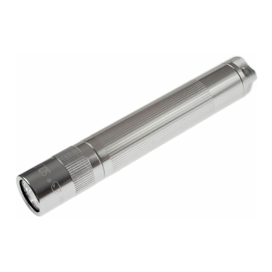
SOLITAIRE
®
FLASHLIGHTS
The distinctive shapes, styles and
overall appearances of all Mag®
flashlights, and the
circumferential inscriptions
extending around the heads of all
Mag® flashlights are trademarks
of Mag Instrument, Inc. The
circumferential inscription on the
head of every flashlight signifies
that it is an original Mag®
flashlight and part of the Mag®
family of flashlights. U.S.
CORPORATE OFFICE
Trademark Registrations for the
MAG INSTRUMENT, INC.
shape, style and overall
1635 S. Sacramento Ave.
appearance trademarks of Mag®
P.O. Box 50600
flashlights and for circumferential
inscription trademarks of Mag®
Ontario, California U.S.A. 91761-1083
flashlights include Nos. 1,808,998;
Website: www.maglite.com
2,074,795; 2,687,693; 2,745,460;
Warranty: Tel: (800) 283-5562 or
2,765,978 and 2,765,979.
(909) 947-1006
The Solitaire® Single Cell AAA
Fax: (909) 947-5041
flashlight is covered by one or
E-mail: warranty@magmail.com
more pending patent applications
and U.S. Patent Nos. 4,577,263;
Sales & Parts:
4,656,565; 4,658,336; 4,819,141;
Tel: (800) 289-6241 • (909) 947-1006
4,851,974; 4,864,474; 4,899,265;
E-mail: salesdesk@magmail.com
4,942,505; 5,003,440; 5,052,602;
5,113,326; 5,143,441; 5,207,363;
©2004 MAG INSTRUMENT, INC.
5,207,502; 5,293,307; 5,349,506;
6,135,611; 6,170,960; Des.
421-000-447 8/04
308,109. and by foreign patents.
Tool required to
replace the switch
in the Solitaire®.
(included)
Tool has a long
and short pin
end. The long
pins remove the
switch. The short
pins are to install
the switch.
© 2004 Mag Instrument, Inc. 421-000-447 8/04
SCHEMATIC - FLASHLIGHT
Parts List for Standard Black Solitaire
ITEM NO
QTY.
PART NUMBER
1
1
108-000-089
2
1
220-000-055
3
1
108-000-067
4
1
108-000-083
5
1
108-000-084
6
1
LK3A001
7
1
108-000-269
8
1
*
9
1
108-000-067
10
1
220-000-067
11
1
*
12
1
*
13
1
*
14
1
108-000-190
15
1
108-000-069
16
1
108-000-618
17
1
108-000-204
18
1
220-000-156
19
*
108-000-085
20
1
112-000-003
®
Flashlight
DESCRIPTION
Head Sub-Assembly
Head, Black
'O' Ring, Head
Clear Lens
Reflector
Bulb
Barrel & Switch Sub-Assembly
Upper Insulator Receptacle
'O' Ring, Barrel
Barrel, Black
Lamp Receptacle, Side Contact
Lamp Receptacle, Center Contact
Lower Insulator Receptacle
Tail cap Sub-Assembly
Spring, Tail cap
Electrical Contact
Lip Seal
Tail cap, Black
Switch Assembly
Short/Long Pin Tool
Switch Removal
STEP 1
Unscrew (counter
clockwise) and remove
the entire TAIL CAP
ASSEMBLY (14) and
the battery.
Note: A spare LAMP (8) is
located in the TAIL CAP (20).
STEP 2
Unscrew (counter
clockwise) and remove
the entire HEAD
ASSEMBLY (1)
STEP 3
Remove the LAMP (6) by
pulling it straight out of
the receptacles.
WARNING: Do not allow children to
install or tamper with the lamp.
Protect the lamp from bending or
twisting. If the lamp is installed
improperly or if the leads from the
lamp are twisted so as to contact one
another, this could short circuit the
flashlight and cause heat generation.
STEP 4
Insert the end of the TOOL
(20) with the longest pin
protrusion into the bottom
of the BARREL (10). Rotate
the tool until the two pins
enter the two holes in the
bottom of the LOWER
INSULATOR (13).
STEP 5
Place the TOOL (20) and
the BARREL (10) on a flat
surface and push down on
the BARREL (10). The
UPPER INSULATOR (8)
will move upward and
separate from the LOWER
INSULATOR (13).
STEP 6
You can now remove the
UPPER INSULATOR (8)
from the BARREL (10).
STEP 7
Slowly lift the BARREL
(10) off of the TOOL (20),
the LOWER INSULATOR
(13) should be on the
TOOL (20). If not, tap the
BARREL (10) lightly and
the LOWER INSULATOR
(13) should fall out.
Advertisement
Table of Contents

Related Manuals for Mag-lite SOLITAIRE Series


Summary of Contents for Mag-lite SOLITAIRE Series
- Page 1 Switch Removal SCHEMATIC - FLASHLIGHT STEP 1 Unscrew (counter clockwise) and remove the entire TAIL CAP ASSEMBLY (14) and FLASHLIGHTS the battery. Note: A spare LAMP (8) is located in the TAIL CAP (20). Switch Repair STEP 2 Instructions for Unscrew (counter clockwise) and remove the entire HEAD...
- Page 2 Preparing Replacement Switch Assembly Solitaire ® Lens / Reflector Replacement Replacement switches come To separate the SWITCH Push down on the lower half of STEP 1 STEP 2 assembled. ASSEMBLY (19) prior to the SWITCH ASSEMBLY (19), These are the components of the Place the TOOL (20) against the installation, place the SWITCH this will cause the UPPER...
Need help?
Do you have a question about the SOLITAIRE Series and is the answer not in the manual?
Questions and answers