Table of Contents
Advertisement
Pilot's Guide
Engine Data Management
EDM-700
EDM-800
Copyright © 2001 J.P. Instruments, Inc.
All Rights Reserved
J.P. INSTRUMENTS INC.
Information: P. O. Box 7033
Huntington Beach, CA 92646
Factory: 3185 B Airway
Costa Mesa, CA 92626
(714) 557-5434
www.jpinstruments.com
Printed in the United States of America
Fax (714) 557-9840
Rev P 05/2001
Advertisement
Table of Contents

Related Manuals for J.P. Instruments EDM-700


Summary of Contents for J.P. Instruments EDM-700
- Page 1 Pilot’s Guide Engine Data Management EDM-700 EDM-800 Copyright © 2001 J.P. Instruments, Inc. All Rights Reserved J.P. INSTRUMENTS INC. Information: P. O. Box 7033 Huntington Beach, CA 92646 Factory: 3185 B Airway Costa Mesa, CA 92626 (714) 557-5434 Fax (714) 557-9840 www.jpinstruments.com...
-
Page 2: Table Of Contents
Table of Contents SECTION 1 - ............. INTRODUCTION ................5 RODUCT EATURES ............... 5 NGINE ANAGEMENT ..........2 ENEFITS OF ROPER IXTURE ONTROL JPI P ..................2 ROBES .............. 2 EMPERATURE AND IXTURE SECTION 2 - ..........DISPLAYS AND CONTROLS ..................4 ISPLAYS .................... - Page 3 ....33 ARAMETER TART EQUENCE WITH PTION SECTION 7 - ........LONG TERM DATA MEMORY SECTION 8 - ............PERSONALIZING ............... 39 ILOT ROGRAMMING SECTION 9 -PROGRAMMING THE EDM-800 HORSEPOWER CONSTANT ..................41 SECTION 10 - PROGRAMMING MANIFOLD PRESSURE (MAP) ..42 SECTION 11 - PROGRAMMING USE OF FACTORY ORIGINAL TIT PROBE SECTION 12 - PROGRAMMING THE FUEL FLOW OPTION ....
- Page 4 How to Change Modes (page 7) EDM-700 enters Automatic mode two minutes after power up...
-
Page 5: Product Features
Section 1 - Introduction Product Features EDM 700/800 Standard Instrument: Fuel Flow Option: • • Hands-free, automatic scanning Solid-state pulse generating rotor • All programming done from the fuel flow transducer • Front Panel Fuel quantity measured in gallons, • LeanFind™... -
Page 6: Benefits Of Proper Mixture Control
EDM it is now possible to have substantially more diagnostic information available to you in a timely and usable manner. The real-time serial data port—a standard feature—permits you to record scanned parameters in real-time using a user-supplied Palm™ Computer or laptop PC. Benefits of Proper Mixture Control •... - Page 7 As the mixture is leaned, EGT rises to a peak temperature, and then drops as the mixture is further leaned. Peak power occurs at a mixture using more fuel than at peak EGT. Best economy occurs at peak EGT. Accurate leaning yields optimal engine temperatures. By being able to precisely adjust the mixture, your engine can produce either the best fuel economy or maximum power, whichever you choose.
-
Page 8: Displays
compression will cause each cylinder to follow its own mixture and temperature relationship such that one cylinder will reach peak before another. Section 2 - Displays and Controls The EDM monitors engine temperatures and voltages, assists in adjusting the fuel/air mixture, and helps diagnose engine malfunctions. There are three components of the user interface: •... - Page 9 • Normalize view: when there is a dash _ near the N at the top of the display (EDM-700) or the letters NRM are lighted on the left side (EDM-800), the EGT columns are displayed normalized. When you change to the Normalize view, all column peaks are set to the same half-height level for trend analysis.
- Page 10 ‚Temperature Units (°F or °C) • °F temperatures in the digital display are in Fahrenheit degrees. • °C temperatures in the digital display are in Celsius degrees. To change the display of engine temperatures see “Changing the Alarm Limits” on page 45. ƒ„Cylinder Numbers and Dot Index A row of numbers 1 through 6 and the letter T are the column labels for the analog display.
-
Page 11: Modes
EGT and CHT When the dot index is beneath a cylinder number, 1 through 6, the digital display shows the EGT on the left (four digits) and the CHT on the right (three digits). Other parameters are displayed in the digital display as described in the subsection “Parameter Scan—Systems without Fuel Flow Option”... -
Page 12: Buttons
Manual Mode Just tap the STEP button. Automatic stops. Each indexed parameter is frozen in the digital display until you manually index to the next parameter by tapping the STEP button. If no button is depressed for 15 minutes, the Automatic Mode will resume. LeanFind Mode Simply pre-lean, tap the LF button and begin leaning. - Page 13 • When an alarm is displayed, tapping the STEP button will temporarily delete that alarm from appearing for the next ten minutes. • When an alarm is displayed, holding the STEP button until the word OFF appears will delete that alarm from appearing for the remainder of the flight.
-
Page 14: Parameter Scan-Systems Without Fuel Flow Option
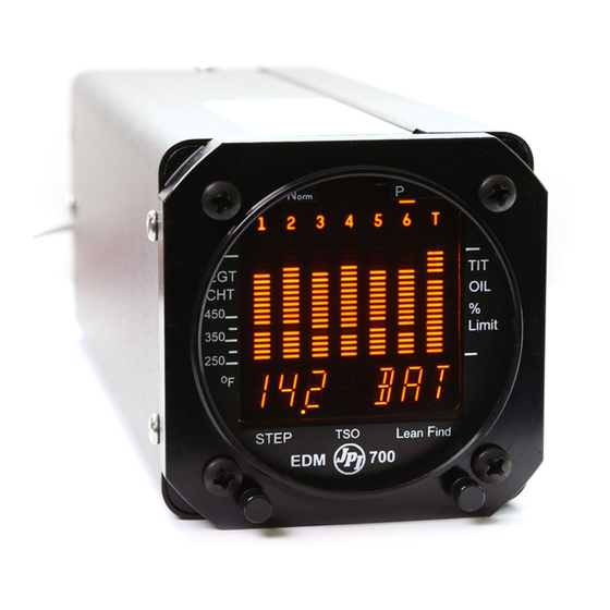
Parameter Scan—Systems without Fuel Flow Option The EDM steps through the engine parameters in a specific sequence. Listed below is the sequence, parameter description and example of the digital display. Parameter Example Comments Voltage, System Bus I4.2 BATTERY VOLTAGE Outside Air °F or °C Temperature Induction Air... -
Page 15: Diagnostic Testing On Startup And During Flight
Section 3 - Operating Procedures Diagnostic Testing on Startup and During Flight When your EDM is first turned on, all digits light up for a few seconds, permitting you to check for non-functional segments. Then each column is self-tested in sequence while the EDM tests internal components, calibration and integrity of the probes. -
Page 16: Manual Mode
You may disable the Automatic mode by setting “0” for scan rate. LeanFind Mode—Leaning Rich of Peak JPI’s EDM-700 and EDM-800 provide two methods of leaning: lean rich of peak (LEAN R) or lean of peak (LEAN L). - Page 17 method, and provides the procedure for the lean of peak method. The default method is set to rich of peak. Simply pre-lean, tap the LF button and begin leaning. Upon reaching cruise configuration, you will use the LeanFind mode to identify the first cylinder to reach peak EGT.
- Page 18 LeanFind Procedure—Step-by-Step Procedure Example Comments Establish cruise at approx. 65 to 75% power. *For your first flight with the I490 PRE-LEAN THE MIXTURE EDM, use the method shown TO 50°F ESTIMATED RICH below. OF PEAK EGT ON ANY CYLINDER: _____° Wait one minute Let engine stabilize.
-
Page 19: Leanfind Procedure-General Explanation
I2.3 *Determining the pre-lean value: while in cruise at under 65 percent power, choose any cylinder and lean that cylinder to peak EGT in the Manual mode or to engine roughness, whichever occurs first. Note the peak, subtract 50° and write the resulting number in the space provided in step 2. - Page 20 Continue leaning slowly. With a vernier mixture control, turn the knob about a quarter turn every second. With a non-vernier or quadrant mixture control, lean slowly and smoothly about 1/16 inch every five seconds. Eventually, one cylinder will reach peak before any of the other cylinders.
- Page 21 If you lean too much, the EGT will drop and the engine will be operating lean of peak. Lean of Peak Leaning with GAMI injectors To use the “lean of peak” method, tap LF and then immediately hold both STEP and LF until you see LEAN L.
- Page 22 (flashing dot) you cannot change leaning methods. You may toggle back to LEAN by holding both buttons again. In the “lean of peak” method the columns will invert with the first to peak progressing down from the top of the display. The inverted column scale is 5°...
- Page 23 the factory-installed probe and gauge, and this gauge reading is the limiting factor when adjusting your engine. For Your Safe Flight Page 19...
-
Page 24: Operation For Each Phase Of Flight
Operation for each Phase of Flight Engine Run-Up Suggested setup: Verify: • uniform rise of about 50°F in all EGTs in single Runup RPM magneto operation • uniform rise of EGTs with application of the Normalize view mixture control. Be alert for: Manual mode •... -
Page 25: Shock Cooling
Cruise After the engine is warmed up, use LeanFind to lean the mixture. Suggested setup: Be alert for: • uneven EGTs or CHTs (carbureted engines). Percentage view Make fine adjustments to throttle, then RPM, then mixture to level the display columns. Automatic mode •... -
Page 26: Common Misapplications
Common Misapplications Some of the more common misapplications made by first-time EDM users are presented here in an attempt to help you avoid similar problems. Problem Situation Correction LeanFind finds a Failure to pre-lean Follow the pre-lean “peak” too soon. before performing procedure in the LeanFind or stopping... - Page 27 Section 4 - Diagnosing Engine Problems Typical Normal Parameters The follow chart lists typical normal parameter values that you will observe for most general aircraft engines. Parameter Normal range Comments EGTs in Cruise 1350°F • under 200 HP 1550°F • high performance •...
- Page 28 available to occupy the same socket as the factory original probe. Contact your dealer. Page 24 Engine Data Management...
- Page 29 Engine Diagnosis Chart The following chart will help you diagnose engine problems in your aircraft. (Views are Percentage views). Notice that there will be always one CHT that is shown hotter than the others. Display Symptom Probable Cause Recommended Action 75°...
- Page 30 Display Symptom Probable Cause Recommended Action EGT and CHT Dirty fuel injectors Check injectors and not uniform or fouled plugs. plugs. Non- uniformity is normal for carbureted engines Decrease in Decrease in airflow Check for change EGT for all into the induction in manifold cylinders system.
-
Page 31: Alarms
Display Symptom Probable Cause Recommended Action Loss of peak Poor ignition or Have magneto (no picture) vapor in fuel tested. injection system. Decrease in Detonation. Usually Enrich mixture, (no picture) peak or flat the result of 80 reduce power and EGT response Octane fuel in 100 relean mixture. -
Page 32: Pre-Ignition And Detonation
When an alarm is displayed, holding the STEP button until the word OFF appears will disable that alarm indication for the remainder of the flight. See “Alarm Limits” on page 44. Alarm Priority If multiple alarms occur simultaneously, the higher priority alarm will temporarily “mask”... - Page 33 ignition will destroy your engine in less than a minute unless you take immediate corrective action. Section 5 - Data Logging On monthly intervals, you may choose to jot down peak EGT, parameter sequence values, and cruise engine settings on a data logging worksheet in the back of this book.
-
Page 34: Fuel Flow Display Select Switch
Section 6 - Fuel Flow Option Operation Fuel Flow Display Select Switch The select switch is a three-position toggle switch mounted on your instrument panel near the display of the EDM. It affects only the display scan. • In the EGT (Temperature) position only the installed temperature (and battery voltage) parameters are displayed. - Page 35 Refer to the column in the chart below corresponding to your fuel tank configuration. Tap the LF button to select one of the four following fueling choices on the left column of the chart. LF to Main tanks Main tanks Main &...
-
Page 36: Fuel Management
Accumulate Total—Trip Total You may either display total fuel used since the last time you informed the EDM that the aircraft was refueled, or for an extended trip with multiple fuel stops. This selection affects only the USD parameter. How to select whether to accumulate or reset is described in “Pilot Programming”... -
Page 37: Parameter Start Up Sequence With Fuel Flow Option
Parameter Start Up Sequence with Fuel Flow Option The first column indicates what position the select switch must be in to display that particular parameter. T is EGT, F is FF and A is ALL. Select Parameter Switch Description Example Comments T, A Voltage, System Bus... - Page 38 T, A EGT, CHT EGT, left, CHT, right. Dot I340 indicates cylinder T, A TIT, Turbine Inlet Turbine #1, left and fuel flow I370 Temperature right I3.5 T, A Oil Temperature I 7 8 T, A Shock Cooling Dot indicates fastest cooling cylinder Page 34 Engine Data Management...
- Page 39 For fuel calculations to be accurate, it is imperative that you inform the EDM of the correct amount of fuel aboard the aircraft. Do not rely on fuel flow instruments to determine fuel levels in tanks. Refer to original fuel flow instrumentation for primary information Section 7 - Long Term Data Memory The EDM Long Term Data Memory will record and store all displayed parameters once every six seconds (or at the programmed interval of...
- Page 40 appear in the output data file. The aircraft id can be your aircraft registration number or your name. Initially the aircraft ID is set to the EDM's serial number. You may change the record interval from 2 to 500 seconds, even in flight. When you change the interval in flight, the current flight file is closed, and a new flight file is created with the new record interval.
- Page 41 Tap the EzCapture™ button. The Palm Computer will wait a few seconds for you. 5. On the EDM-700/800, tap the STEP button to begin the transfer process. The EDM-700/800 display shows the percentage of memory remaining to be transferred. When this number reaches zero, the transfer is complete.
- Page 42 complete, simultaneously hold the STEP and LF buttons for five seconds. 6. The Palm Computer will close the file named with today’s date. Tap Exit to end EzPalm or tap Explorer to view the file list. 7. The EDM display will show SAVE D?N. •...
-
Page 43: Pilot Programming
The next labels are E1…E6 for EGTs, then C1…C6 for CHTs. The DIF, CLD, OAT, BAT, FF and USD are the same as on the EDM-700 display. The MARK field will be an “S” if the data was marked by pressing the LF button twice. - Page 44 Tap STEP Tap LF to to advance sequence to the next through item these values Comments T, F, PROGRAM STAYS ON FOR TWO SECONDS. HOLD BOTH BUTTONS FOR 5 SECONDS SET UP THE FACTORY ORIGINAL TIT (SEE PAGE 40). N ⇔ Y T, F, Y—Yes—to change fuel status (see page FUEL ?
-
Page 45: Section 9 -Programming The Edm-800 Horsepower Constant
F, A KF-set, hold both STEP and LF buttons KF-SET 29.00=K simultaneously for five seconds to begin the next sequence. 29.00=K One digit will be flash and the LF 9.00 button will adjust up or down. STEP to next digit. Hold both buttons to exit set mode. -
Page 46: Section 10 - Programming Manifold Pressure (Map)
adjusting the HP constant in the lower display by holding or tapping the LF button. Note: the reading is the percent of maximum HP, not total HP. 4. Keep adjusting the HP constant until the upper window displays the same power level as the current engine percent HP. 5. -
Page 47: Section 11 - Programming Use Of Factory Original Tit Probe
Do not set MAP to the local altimeter (Kollsman window) setting since that setting is the pressure at sea level, and is not the same as your field elevation pressure. Tap or hold the LF button to change the MAP value. 7. -
Page 48: Section 12 - Programming The Fuel Flow Option
Section 12 - Programming the Fuel Flow Option Fuel Flow Parameters Three additional parameters may be set by the pilot when the Fuel Flow Option is installed: • K Factor—the fuel flow transducer calibration constant. • Accumulate—default is OFF: resets the fuel used to 0 every time you inform the EDM that the aircraft was refueled. -
Page 49: Fuel Flow Option Programming Procedure
Fuel USED shown by EDM Flight (total tank - REM) Actual fuel used by topping tanks Œ • Total 2. Total Œ the EDM fuel used and • the actual fuel used. 3. Record the current K factor here Ž____________________ and in the table below. -
Page 50: Section 13 - Programming Long Term Data Memory
3. Tap or hold the LF button to change flashing digit: 9.00 4. Tap STEP button for next digit: I 5. Tap or hold the LF button to change flashing digit: I 6. Tap STEP button for next digit: I8. 7. - Page 51 selects the first character. STEP moves to the next character. To Save , hold both STEP and LF for 5 sec. Tap STEP button to exit the procedure. For Your Safe Flight Page 47...
-
Page 52: Section 14 - Alarm Limits
Section 14 - Alarm Limits Factory Set Default Limits—Non-Primary JPI conservatively sets the default alarm limits below Lycoming and Continental recommendations. Parameter Default Low Limit Default High Limit Alarm Example 450°F 230°C 90°F 32°C 230°F 110°C I 720 1650°F 900°C -60°F/min. - Page 53 The display will then sequence as shown in the chart below. Tap the STEP button to advance to the next item in the list. Tap the LF button to select alternate values of that item. Hold the LF button to increase a numerical value;...
- Page 54 Changing the Alarm Limits Procedure: Tap STEP LF sequences through to next item these value ranges Description N ⇔ FAC? Restore factory defaults? FAC? FAC? ENG F ⇔ ENG C Select F or C degrees for ENG F all engine temps. You must also change the alarm limits to °F or °C.
-
Page 55: Map, Fuel Flow Alarm Limits, Units, Fuel Capacity
N ⇔ Y—Yes—carbureted CARB? CARB? engine CARB? Long Term Memory. RECRD? RECRD? Y⇔ Y—only data recording. RECRD? N—only real-time data output. (EDM-800 only) Set the CYL=6 CYL=4 … CYL=I 2 number of cylinders. See page 48 for exceptions. Y ⇔ END Y—Yes to exit;... -
Page 56: Section 15 - Real-Time Serial Data Port
Low Time Alarm Limit Select the value of the time remaining, in minutes, that triggers the alarm. Time remaining is calculated at the current fuel flow rate. Low Fuel Alarm Limit Select the value of the fuel remaining, in the selected fuel flow units, that triggers the alarm. - Page 57 Table of header names for parameters: header name parameter header name parameter “E1” EGT cylinder 1 “OIL” oil temp “E2” EGT cylinder 2 “DIF” EGT span “E3” “CLD” EGT cylinder 3 shock cooling “E4” EGT cylinder 4 “OATF” outside air temp. “E5”...
-
Page 58: Navigation Data Formats
2.5mm ID 5.5mm OD plug 9 pin D subminiature female Signal Outer barrel Pin 5 ground Inner barrel Pin 2 signal J. P. Instruments provides a data capture computer program for the PC called EzRec™. Or you may use terminal emulator software for display and data capture, such as HyperTerminal, supplied with MS Windows. -
Page 59: Diagnostic Messages, Fuel Flow
Diagnostic Messages, Fuel Flow The following displays indicate a malfunction in the Fuel Flow Option transducer or associated electrical connections: Zero’s indicate Fuel flow is too low to register Dashes indicate No fuel flow transducer signals Dashes indicate No fuel flow transducer signals GPS Interface Diagnostics Parameters REQ, RES, &... -
Page 60: Section 16 - Option Connector Pin Assignments
Fuel Data (input to GPS; output of EDM) RS-232. Serial data format: 8 data, 1 start, no parity. Baud rate: 9,600. Output format is determined by the GPS-C setting, but may be over- ridden by the GPS navigation format: If the EDM senses Northstar or NMEA-183 navigation data input, there will be no fuel data output. -
Page 61: Section 17 - Reference Reading
JPI offers both e-mail and telephone technical support. Have your model and serial number ready when you call. Call JPI for a return authorization number before returning any equipment. J.P. INSTRUMENTS Inc. 3185 B Airway Costa Mesa, CA 92626 800 345-4574 www.jpinstruments.com... -
Page 62: Limited Warranty
Limited Warranty J.P. Instruments Inc. (JPI) warrants all parts in your new EDM to be free from defects in material and workmanship under normal use. Our obligation under this warranty is limited to repair or exchange of any defective part of this unit if the part is returned, shipping prepaid, within two years for electronics and one year for probes from the date of original purchase. -
Page 63: Index
Index horsepower, 40 internal self test, 11 K-factor, 43 manifold pressure (MAP), 41 Accumulate, 40, 45 OAT, 39 total, 31 TIT, factory original, 42 Adapter probe, CHT, 23 Capacity, fuel tank, 29 Adding fuel, 30 CARB?, 49 Adjusting Carburetor, 51 K-factor, 43 ice, 25 OAT, 39... - Page 64 ports, GPS, 54 EzCapture™, 36 Data logging EzPalm™, 35 manual, 28 EzRec™, 52 worksheet, 28 EzSAVEP™, 36 Data output serial port, 51 software, 52 Default alarm limits, 47 Factory default alarm limits, 47 Defueling, 30 Factory original TIT probe, 42 Descent, 21 Fahrenheit Detonation, 26, 27...
- Page 65 32 Magneto check, 20 Induction, 25 MAIN, 49 air temperature, IAT, 10, 32 Manifold Air Pressure (MAP) Informing the EDM-700 calibration, 41 startup fuel, 29 Manual indexing mode, 8 Injectors. See Fuel, injectors Manual mode, 12 Intake valve, 24...
- Page 66 Misapplications, 22 Missing column, 24 Palm Computer, 35 segment, 6 Parameter indexing, 10, 31 Mixture, 2, 15 Peak EGT, 15 best economy, 3 PEAK EGT, 14, 16 best power, 3 Percentage view, 5 Modes, 7, 11 Pilot programming, 38 MPG, MPK, MPL, MPP, 32 alarm limits, 47 MS Excel, 34 data recording, 45...
- Page 67 Resolution, EGT display, 39 Tapping a button, 8 Rich of Peak, 13 Technical support, 56 Rough engine, 24 Test, self, 11 RS-232, 51, 54 Time to empty, 32 Run-up, 20 Timing, ignition, 24 TIT, 10, 18 factory original probe, 42 missing segment, 6 Toggle, N, P, 5 Scanning.
- Page 68 EDM-700 Data Logging Worksheet A/C N ________ Make ______ Model _____ Engine _________ EGT / CHT Date Tach Page 64 Engine Data Management...
Need help?
Do you have a question about the EDM-700 and is the answer not in the manual?
Questions and answers