Table of Contents
Advertisement
Pilot's Guide
Engine Data Management
EDM-700
EDM-800
EDM-711
Copyright 2000-2007 J.P. Instruments, Inc.
J.P. INSTRUMENTS INC.
Information: P. O. Box 7033
Huntington Beach, CA 92646
Factory: 3185 B Airway Avenue
Costa Mesa, CA 92626
(714) 557-5434 (800) 345 4574
Fax (714) 557-9840
www.jpinstruments.com
Support@jpinstruments.com
Printed in the United States of America
Last printed 11/13/2017 3:30:00 PM
Primary
All Rights Reserved
Rev X 11/2017
Advertisement
Table of Contents

Related Manuals for J.P. Instruments EDM-700


Summary of Contents for J.P. Instruments EDM-700
- Page 1 Pilot’s Guide Engine Data Management EDM-700 EDM-800 EDM-711 Primary Copyright 2000-2007 J.P. Instruments, Inc. All Rights Reserved J.P. INSTRUMENTS INC. Information: P. O. Box 7033 Huntington Beach, CA 92646 Factory: 3185 B Airway Avenue Costa Mesa, CA 92626 (714) 557-5434 (800) 345 4574 Fax (714) 557-9840 www.jpinstruments.com...
-
Page 2: Table Of Contents
JPI Probes Temperature and Mixture Section 2 - Displays and Controls Displays Modes Buttons Parameter Scan— EDM-700 without Fuel Flow Options Automatic Parameter Scan—EDM-711 Section 3 - Operating Procedures Diagnostic Testing on Startup and During Flight Modes Automatic Mode Manual Mode LeanFind Mode—Leaning Rich of Peak... - Page 3 Section 17 - Technical Support Limited Warranty Index How to Change Modes (page 7) EDM-700 enters Automatic mode two minutes after power up tap STEP and tap STEP button LFsimultaneously AUTO INDEX MANUAL INDEX Toggle to include/ parameters parameters exclude...
-
Page 5: Section 1 - Introduction
Section 1 - Introduction Product Features indicates standard feature Hands-free, automatic scanning (711: primary only) All programming done from the Front Panel LeanFind finds the first and last cylinder to peak with true peak detect—eliminates a false peaks ... -
Page 6: Engine Data Management
Engine Data Management The EDM Engine Data Management system is the most advanced and accurate piston engine-monitoring instrument on the market. Using the latest microprocessor technology, the EDM will monitor up to twenty- four critical parameters in your engine, four times a second, with a linearized thermocouple accuracy of better than 0.1 percent or 2 F°. - Page 7 From the cockpit you can adjust the fuel/air ratio by a process called leaning. Retarding the mixture control changes the fuel/air ratio and hence the resulting Exhaust Gas Temperature (EGT). The following figure depicts the mixture and temperature relationship. Best Best power economy...
-
Page 8: Section 2 - Displays And Controls
A single EGT gauge merely gives you an average of each cylinder’s temperature: some cylinders can be too rich, while others too lean. Variations produced by differences in fuel distribution, ignition, and compression will cause each cylinder to follow its own mixture and temperature relationship such that one cylinder will reach peak before another. - Page 9 Normalize view: when there is a dash _ near the N at the top of the display (EDM-700) or the letters NRM are lighted on the left side (EDM-800), the EGT columns are displayed normalized. When you change to the Normalize view, all column peaks are set to the same half-height level for trend analysis.
- Page 10 To change the display of engine temperatures see “Changing the Alarm Limits” on page 43. Cylinder Numbers and Dot Index A row of numbers 1 through 6 and the letter T are the column labels for the analog display. The 1 through 6 are the cylinder numbers. If the TIT option is installed, the T denotes the last column is displaying Turbine Input Temperature (TIT) as a column.
-
Page 11: Modes
“Parameter Scan— EDM-700 without Fuel Flow Option” on page 9. The EDM-711 will briefly display EGT – CHT before displaying the numerical values. Limit 4 digit display of I340 376 3 digit STEP J P I... -
Page 12: Buttons
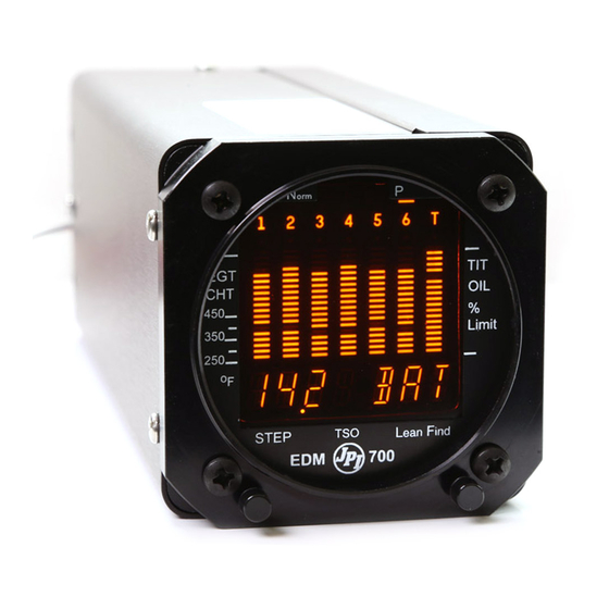
Simply pre-lean, tap the LF button and begin leaning. The EDM will assist you in finding the first cylinder to peak. Buttons I340 376 STEP EDM-700 J P I STEP button LF button Buttons, Front Panel Two operating buttons control all functions of the EDM. -
Page 13: Parameter Scan- Edm-700 Without Fuel Flow Options
SNAP. Parameter Scan— EDM-700 without Fuel Flow Options The EDM steps through the engine parameters in a specific sequence. Listed below is the sequence, parameter description and example of the digital display. -
Page 14: Automatic Parameter Scan-Edm-711
Parameter Example Comments I4.2 BAT Voltage, System Bus Battery voltage Outside Air Temperature °F or °C Out of the intercooler Induction Air Temperature Compressor Discharge Into the intercooler Temperature Carburetor Temperature Not available when CDT is installed Dot indicates most widely Difference between deviating cylinder hottest and coolest EGT... -
Page 15: Section 3 - Operating Procedures
Section 3 - Operating Procedures Diagnostic Testing on Startup and During Flight When your EDM is first turned on, all digits light up for a few seconds, permitting you to check for non-functional segments. Then each column is self-tested in sequence while the EDM tests internal components, calibration and integrity of the probes. -
Page 16: Manual Mode
You may disable the Automatic mode by setting “0” for scan rate (disabling Automatic mode does not apply to EDM-711). LeanFind Mode—Leaning Rich of Peak JPI’s EDM-700 and EDM-800 provide two methods of leaning: lean rich of peak (LEAN R) or lean of peak (LEAN L). - Page 17 Establish cruise at approx. 65 to 75% power. Pre-lean the mixture to 50°F I490 *For your first flight with the estimated rich of peak EGT EDM, use the method shown on any cylinder: _____° below. Wait one minute Let engine stabilize. Tap the LF button LEAN Start LeanFind.
-
Page 18: Leanfind Procedure-General Explanation
LeanFind Procedure—General Explanation Lycoming and Continental engines have established specific restrictions on leaning that must be followed, such as percentage of power, climb leaning, and TIT limits. Lycoming recommends operation at peak EGT for power settings of 75% or lower, while Continental recommends operation at peak EGT for power settings of 65% or lower. - Page 19 I360 LF temperature and "LF" STEP EDM-700 displayed J P I Continue leaning slowly without pausing. With a vernier mixture control, turn the knob about a quarter turn every second. With a non-vernier or quadrant mixture control, lean slowly and smoothly about 1/16 inch every five seconds.
- Page 20 I340 SET EGT of the LEANEST cylinder STEP EDM-700 displayed with the J P I the word SET Lean of Peak Leaning with GAMI injectors To use the “lean of peak” method, tap LF and then immediately hold both STEP and LF until you see LEAN L.
- Page 21 will be shown as an inverted bar graph; when the last cylinder peaks its column will flash. The analog display is an inverted bar graph showing where each cylinder peaked. When the LF button is held the display will show the delta fuel flow between the first and last to peak (GAMI Spread), as well as the richest peak EGT.
-
Page 22: Operation For Each Phase Of Flight
Operation for each Phase of Flight Engine Run-Up Suggested setup: Verify: uniform rise of about 50°F in all EGTs in single Runup RPM magneto operation uniform rise of EGTs with application of the Normalize view mixture control. Be alert for: Manual mode ... -
Page 23: Shock Cooling
Cruise After the engine is warmed up, use LeanFind to lean the mixture. Suggested setup: Be alert for: uneven EGTs or CHTs (carbureted engines). Percentage view Make fine adjustments to throttle, then RPM, then mixture to level the display columns. Automatic mode ... -
Page 24: Common Misapplications
Common Misapplications Some of the more common misapplications made by first-time EDM users are presented here in an attempt to help you avoid similar problems. Problem Situation Correction Failure to pre-lean Follow the pre-lean LeanFind finds a before performing procedure in the “peak”... -
Page 25: Section 4 - Diagnosing Engine Problems
Section 4 - Diagnosing Engine Problems Typical Normal Parameters The follow chart lists typical normal parameter values that you will observe for most general aircraft engines. Parameter Normal range Comments EGTs in Cruise 1350°F under 200 HP 1550°F high performance ... - Page 26 Engine Diagnosis Chart The following chart will help you diagnose engine problems in your aircraft. (Views are Percentage views). Notice that there will be always one CHT that is shown hotter than the others. Display Symptom Probable Cause Recommended Action 75°...
- Page 27 Display Symptom Probable Cause Recommended Action EGT and CHT Dirty fuel injectors Check injectors and not uniform or fouled plugs. plugs. Non- uniformity is normal for carbureted engines Decrease in Decrease in airflow Check for change EGT for all into the induction in manifold cylinders system.
-
Page 28: Alarms
Display Symptom Probable Cause Recommended Action Loss of peak Poor ignition or Have magneto (no picture) vapor in fuel tested. injection system. Decrease in Detonation. Usually Enrich mixture, (no picture) peak or flat the result of 80 reduce power and EGT response Octane fuel in 100 relean mixture. -
Page 29: Pre-Ignition And Detonation
When an alarm is displayed, tapping the STEP button will temporarily disable the alarm digital indication for the next ten minutes. When an alarm is displayed, holding the STEP button until the word OFF appears will disable that alarm digital indication for the remainder of the flight. -
Page 30: Section 5 - Fuel Flow Option Operation
ignition will destroy your engine in less than a minute unless you take immediate corrective action. Section 5 - Fuel Flow Option Operation Fuel Flow Display Select Switch The select switch is a three-position toggle switch mounted on your instrument panel near the display of the EDM. It affects only the display scan. - Page 31 Refer to the flow chart. Then tap the STEP button to complete the entry and advance to the Manual mode. Power up Program Adding Fuel and Auxiliary Tanks If you either FUEL ?N a) added less than full fuel to only Refuel the main tanks, or STEP...
-
Page 32: Fuel Management
To reset to zero the amount of fuel used at any point in time, manually step to display USD and hold both buttons for five seconds until the display shows .0 USD. Fuel Management Without a means of measuring fuel flow, you must rely on the aircraft fuel gauges or total time of flight. - Page 33 Select Parameter Switch Description Example Comments T, A I4.2 Voltage, System Bus Battery voltage T, A Outside Air °F or °C Temperature T, A Induction Air Out of intercooler Temperature T, A Into intercooler Compressor Discharge Temperature T, A Carburetor Not available when CDT is Temperature installed...
-
Page 34: Section 6 - Long Term Data Memory
For fuel calculations to be accurate, it is imperative that you inform the EDM of the correct amount of fuel aboard the aircraft. Do not rely on fuel flow instruments to determine fuel levels in tanks. Refer to original fuel flow instrumentation for primary information Section 6 - Long Term Data Memory The EDM Long Term Data Memory will record and store all displayed parameters once every six seconds (or at the programmed interval of... -
Page 35: Downloading From Long Term Memory
At power on, the EDM will execute its self test and then display the date (e.g., I I. I2.0 I), the time (I3.26), the percentage of memory filled since the last save (FULL 24), and the Aircraft ID. Downloading from Long Term Memory To download data from the long term memory to your laptop PC, do the following steps. - Page 36 1. Insert the serial cable plug into the front panel of the EDM. Insert the other end of the serial data cable into the 9-pin jack on the memory box. (The serial cable is supplied with the EDM, not the memory box.) 2.
-
Page 37: Downloading From Usb Flash Drive To A Pc
Downloading from USB Flash Drive to a PC To download your data from the USB flash drive to your PC, follow these easy steps. 1. On your PC, start the EzTrends program. 2. Plug in the USB flash drive into an available USB port. 3. - Page 38 T, A OAT-I0 This step will be normally be skipped. OAT0 … Adjust the indicated temperature up or down OATI0 by up to 10°. For example, OAT3 adjust the OAT 3° higher. T, A Y—Yes—sets the digital display to one- I?N ...
- Page 39 T, F, END Y END Y Y—Yes to exit; N—No to review list again. END N For Your Safe Flight Page 35 ...
-
Page 40: Section 8 - Programming The Edm-800 Horsepower Constant
Section 8 - Programming the EDM-800 Horsepower Constant You must adjust the HP Constant once for your aircraft. The default display will be RPM if Fuel Flow is not operational or you can adjust the display to show RPM instead of HP. Before takeoff, put the EDM in the HP Constant mode. -
Page 41: Section 10 - Programming Use Of Factory Original Tit Probe
You may need to correct the MAP based on the altimeter setting at a sea level airport. A. Enter the pilot program mode by simultaneously holding the Step buttons for five seconds. B. Tap repeatedly until you see—for example— Step/OK . - Page 42 concurrently. Due to the high input impedance of the EDM instrument, it will not affect the accuracy of the factory installed probe or gauge. In normal cruise flight, record the difference between the factory installed TIT gauge and the EDM TIT reading. TIT gauge ________ EDM ________.
-
Page 43: Section 11 - Programming The Fuel Flow Option
Tap STEP to advance Tap the LF button to to the next sequence through Comments item these values PROGRAM Stays on for two seconds. RATE 4 RATE 4 hold both STEP and LF buttons simultaneously for five seconds to begin the next sequence. - Page 44 Fine Tuning the K Factor The K factor shown on the fuel flow transducer does not take into account your aircraft’s particular installation. Fuel hose diameters and lengths, elbows, fittings and routing can cause the true K factor to be different from that shown on the fuel flow transducer.
-
Page 45: Fuel Flow Option Programming Procedure
Fuel Flow Option Programming Procedure Setting the K factor This procedure is different than for setting other parameters. Place the select switch in the FF position. If you haven’t already done so, start the pilot programming procedure, simultaneously hold the STEP and LF buttons for five seconds. -
Page 46: Section 13 - Edm-711 Primary Alarm Display
The EDM-711—There are 3 primary functions available to your EDM- Engine Temperature Limit 700/800 CHT, OIL and TIT. When an EDM-700-800 has primary functions it is called an EDM-711. A Remote alarm lamp is supplied that will function even 460F... -
Page 47: Section 14 - Alarm Limits
Section 14 - Alarm Limits Factory Set Default Limits—Non-Primary JPI conservatively sets the default alarm limits below Lycoming and Continental recommendations. Parameter Default Low Limit Default High Limit Alarm Example 450°F* 230°C 90°F 32°C 230°F* 110°C 20 psi 19 O-P I 720 1650°F* 900°C... - Page 48 Hold both Hold both Tap STEP buttons for 5 buttons for 5 button until seconds until seconds until the words the word the words PROGRAM FAC LIM The display will then sequence as shown in the chart below. Tap the STEP button to advance to the next item in the list.
-
Page 49: Map, Fuel Flow Alarm Limits, Units, Fuel Capacity
42.0 25MAP … 90 MAP MAP over boost alarm (EDM-800 only) FUEL Selects the units in all FUEL GAL parameters where fuel FUEL KGS quantity or fuel rate is FUEL LTR displayed FUEL LBS Main tank capacity, in MAIN=50 MAIN=0 … MAIN=999 units selected AUX? Y—Yes—aircraft has... - Page 50 Main Tank Capacity Enter the total usable fuel capacity of the main tanks in the fuel flow units selected. If you do not have auxiliary tanks or tank tabs, answer “No.” If you answer “Yes,” you will be asked to input the capacity of the auxiliary tanks in the fuel flow units selected.
- Page 51 Initially Entering the Tank Capacity To initialize or change the tank capacities, hold the STEP button while turning on the power to the EDM. The following program steps will be displayed: Tap STEP Tap the LF button to sequence to advance through these values Comments Main tank capacity, in...
- Page 52 Diagnostic Messages, Fuel Flow The following displays indicate a malfunction in the Fuel Flow Option transducer or associated electrical connections: Zero’s indicate Fuel flow is too low to register Dashes indicate No fuel flow transducer signals Dashes indicate No fuel flow transducer signals GPS Interface Diagnostics Parameters REQ, RES, &...
- Page 53 automatically detects the GPS data output format and is independent of the GPS-C setting. For Your Safe Flight Page 49 ...
- Page 54 Fuel Data (input to GPS; output of EDM) RS-232. Serial data format: 8 data, 1 start, no parity. Baud rate: 9,600. Output format is determined by the GPS-C setting, but may be over- ridden by the GPS navigation format: If the EDM senses Northstar or NMEA-183 navigation data input, there will be no fuel data output.
- Page 55 JPI offers both e-mail (support@jpinstruments.com) and telephone technical support. Have your model and serial number ready when you call. Call JPI for a return authorization number RMA before returning any equipment. J.P. INSTRUMENTS Inc. 3185 B Airway Costa Mesa, CA 92626 800 345-4574...
- Page 56 Limited Warranty J.P. Instruments Inc. (JPI) warrants all parts in your new EDM to be free from defects in material and workmanship under normal use. Our obligation under this warranty is limited to repair or exchange of any defective part of this unit if the part is returned, shipping prepaid, within three years for electronics and one year for probes from the date of original purchase.
- Page 57 Index manifold pressure (MAP), 35 OAT, 34 TIT, factory original, 36 Capacity, fuel tank, 26 Accumulate, 34, 39 CARB?, 43 total, 27 Carburetor, 44 Adapter probe, CHT, 21 ice, 23 Adding fuel, 27 temperature, 10, 29 Adjusting Celsius K-factor, 37 display indicator, 5 OAT, 34 engine temperatures, 42...
- Page 58 self test, 11 Fouled spark plugs, 5 DIF, 10, 24, 29, 42 Fuel Dimming, display, 7 accumulate, 27 Display, 4 adding or filling, 27 analog, 4 auxiliary tank capacity, 43 digital, 6 capacity, 26, 43 flashing, 13, 17, 24, 25 injectors, 24 Dot index, 6 injectors, clogged, 2, 18, 23...
- Page 59 35 sequence, 29 Manual indexing mode, 7 Induction, 23 Manual mode, 12 air temperature, IAT, 10, 29 Mark, 30 Informing the EDM-700 Memory box, 31 startup fuel, 26 Methods Initial tank capacity, 45 leaning, 12 Injectors. See Fuel, injectors...
- Page 60 missing segment, 6 Red line, 21 OIL, 10, 29 Reference reading, 48 OIL pressure, 1, 21, 23, 25, 29, 42, 43 REM, 29 Removing fuel, 27 Oil temperature, 10, 29 REQ, 29 RES, 29 OPEN PRB, 11 Reset Operation alarm limits, 41 fuel flow option, 26 alarms, 25 temperature scanner, 4...
- Page 61 Test, self, 11 Time to empty, 29 Timing, ignition, 22 Valve TIT, 10, 16 lifter, 22 factory original probe, 36 stuck, 22 missing segment, 6 Vapor, 24 Toggle, N, P, 5 View Top fuel tanks. See Fill change diagram, 9 Total fuel, 27 normalize, percentage, 5 used, 29...
- Page 62 Quick Reference Guide Normalize View Transfer Data in Memory 1. Connect PC Computer to the Hold LF for three seconds. EDM serial port. Percentage View 2. Hold both STEP and LF until Hold LF for three seconds. the display shows PROGRAM, followed by FUEL? N.
- Page 63 Filled Tanks Leaning Rich of Peak In flight, do this first (on power up, 1. Pre-lean mixture and wait 1 skip to step 4): minute. 1. Hold both STEP and LF until 2. Tap LF and see LEAN R. the display shows PROGRAM, 3.
Need help?
Do you have a question about the EDM-700 and is the answer not in the manual?
Questions and answers