Table of Contents
Advertisement
Quick Links
Pilot's Guide
Engine Data Management
EDM-960
Primary
Copyright 2009-2011 J.P. Instruments, Inc.
All Rights Reserved
J.P. INSTRUMENTS INC.
Information: P. O. Box 7033
Huntington Beach, CA 92646
Factory: 3185-B Airway Ave.
Costa Mesa, CA 92626
(714) 557-3805
Fax (714) 557-9840
www.jpinstruments.com
Rev E 02-16
Printed in the United States of America
Advertisement
Chapters
Table of Contents

Related Manuals for J.P. Instruments EDM-960


Summary of Contents for J.P. Instruments EDM-960
- Page 1 Pilot’s Guide Engine Data Management EDM-960 Primary Copyright 2009-2011 J.P. Instruments, Inc. All Rights Reserved J.P. INSTRUMENTS INC. Information: P. O. Box 7033 Huntington Beach, CA 92646 Factory: 3185-B Airway Ave. Costa Mesa, CA 92626 (714) 557-3805 Fax (714) 557-9840 www.jpinstruments.com...
-
Page 2: Table Of Contents
Table of Contents Section 1 - Getting Started Fuel Flow Computer Basics Control Button Basics Display Screen Basics Remote Auxiliary Display Basics RPM and MAP Display Basics Linear Bar Graphs Display Basics LeanFind Basics Section 2 - Interpreting Data Operation for each Phase of Flight Typical Normal Measurements Engine Diagnosis Chart Section 3 -... - Page 3 Custom Key Card Section 11 - Setting Fuel Calibration Points Getting Started…Collecting Fuel Level Calibration Data After you have collected your data… Troubleshooting the EDM-960 Diagnostic Testing on Startup and During Flight Diagnostic Messages Section 12 - Appendices Shock Cooling...
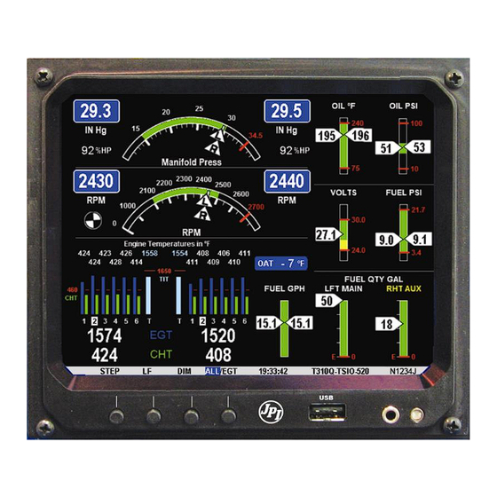
- Page 4 EDM-960 SYSTEM DISPLAYS EDM-960 Main display Remote Auxiliary Display (RAD) Twin Center line thrust Configuration...
- Page 5 Product Features Hands-free, automatic scanning Lean Find finds the first and last cylinder to peak with true peak detect—eliminates false peaks Displays both leaned temperature below peak and peak Voltage monitoring with alarm (see AFMS) Amperes (load or charge/discharge meter) ...
-
Page 6: Getting Started
EDM-960 as a primary instrument. Upon start up, the RAD displays the make and model of you aircraft, which must be verified before you can rely on the EDM-960 for use as the primary engine instrument cluster. The RAD also will continuously notify you of any alarm conditions, regardless of whether you have cleared them on the EDM-960 display. -
Page 7: Fuel Flow Computer Basics
Fuel Flow Computer Basics The fuel flow computer tracks the fuel flowing to the engine and computes various values based on this. At installation, then each time you refuel the aircraft, you must inform the EDM about how much useable fuel is onboard. This is done via the REFUEL function. There are three ‘Quickset’... -
Page 8: Remote Auxiliary Display Basics
Remote Auxiliary Display Basics The Remote Alarm Display ‘RAD’ provides alarm display, RPM and MAP, and is located directly in front of the pilot. Upon power up, the RAD shows the Aircraft model, engine type and declares instrument status: ‘Primary’ (if applicable). -
Page 9: Linear Bar Graphs Display Basics
Linear Bar Graphs Display Basics The Bar Graphs section contains seven dedicated bar graphs with digital display organized as shown to the right. Pointers move up and down for each engine in response to value changes and digital readouts turn red when exceedances occur. -
Page 10: Leanfind Basics
Scanner® Display Basics The EDM Scanner section is located in the lower left area of the screen. It consists of a graphical display of EGT and CHT (and TIT if so equipped) and a digital display that automatically scans the various parameters. -
Page 11: Interpreting Data
Section 2 - Interpreting Data Operation for each Phase of Flight (Worth adding to your run-up checklist.) Suggested setup: Set engine to run-up RPM Engine Run-Up Normalize view Manual mode Verify: uniform rise of about 50°F in all EGTs in single magneto operation. - Page 12 Suggested setup: Standard view Take-Off, Automatic mode Climb, and Verify: Full EGTs and CHTs consistent with past climbs. Throttle EGTs should be in the 1100 to 1300°F range Operations (100° to 300°F cooler than cruise) due to fuel cooling.
-
Page 13: Typical Normal Measurements
Typical Normal Measurements The following chart lists typical normal measurement values that you will observe for most general aircraft engines. Your particular engine’s ranges may not fall within these values. Measurement Typical Range Comments 1350°F under 200 HP engines high performance engines EGTs in Cruise (Note: EGT should drop 1550°F... -
Page 14: Engine Diagnosis Chart
Engine Diagnosis Chart The following chart will help you diagnose engine problems in your aircraft (note: only one engine is shown). Display Symptom Probable Recommended Cause Action TIT ~100° This is normal higher than EGTs 75° to 100° Spark plug not Enrich mixture to EGT rise for firing due to fouling,... - Page 15 Continued: Display Symptom Probable Recommended Cause Action Decrease in Intake valve not Have valve lifter or EGT for one opening fully; faulty rocker arm cylinder valve lifter. checked. Increase in DIF Low compression Check at low RPM (blow by) in cylinder compression.
- Page 16 Display Symptom Probable Recommended Cause Action Rapid rise in Detonation. Reduce power. CHT of one cylinder Pre-ignition - > Full rich & reduce Sudden off power. scale rise for any or all Normalize view - > Change to cylinders Standard view or failed probes - >...
-
Page 17: Displays And Controls
Section 3 - Displays and Controls The EDM monitors engine temperatures, pressures and voltages, assists in adjusting the fuel/air mixture, and helps diagnose engine malfunctions. There are multiple components of the user interface: Four front panel operating buttons below the bottom of the display. ... - Page 18 Button In Automatic or Manual modes, tapping the LF button will activate the Lean Find mode. In the LF mode holding the LF button after peak EGT is found will display the peak EGT. In Automatic or Manual modes holding the LF button for three seconds will toggle between Standard and Normalize (NRM) views.
-
Page 19: Rpm And Map Displays
RPM and MAP Displays The upper left side of the display shows RPM above the MAP. The arcs represent the analog values. Percent horsepower is shown below the MAP readouts. Scanner Displays Digital CHT EGT (blue) Cylinders 1 thru 6 T is TIT CHT (white) White square is... - Page 20 Scanner Digital Display Located under the Scanner bar graph area is the alphanumeric display. It displays alphanumeric values for different parameters as well as status and alarm messages. Normalize / Standard View To toggle between Standard and the Normalize views, hold the LF button for three seconds until the NRM icon toggles on or off.
- Page 21 Temperature Units (°F or °C) The EDM can display engine temps in either °F or °C (Fahrenheit or Celsius). In Primary configurations, this is set to the same units as the configuration the aircraft was originally certified to. Linear Gauge Display Section The linear bar graphs are arranged in a three by three matrix on the right half of the display.
- Page 22 The range of the bar graphs depends on the programming. Range, redlines and/or limits are typically set to match the original aircrafts gauge markings. These are locked for Primary installations, however non- primary gauges can be user modified, using the ‘EDM Config’ which is currently available through the front panel buttons.
-
Page 23: Remote Auxiliary Display
Remote Auxiliary Display See the important note on page 1 regarding the RAD. The remote auxiliary display ‘RAD’ provides redundancy and allows positioning a smaller display directly in front of the pilot. Upon power up the RAD displays the EDM’s programmed configuration (aircraft make and model and primary status). -
Page 24: Operating Modes
Section 4 - Operating Modes The EDM has four basic operating modes: Automatic, Manual, Program and Lean Find. Lean Find is described in the next section; Program mode is described on page 40, ‘First Time Setup and Customization’. When you first turn on the power the EDM starts in the Manual mode, but will enter the Automatic mode after a few minutes. -
Page 25: Manual Mode
Manual Mode To activate Manual Mode, just tap the STEP button. Use Manual mode to lock on one measurement, such as your hottest CHT. Select desired parameter by tapping STEP button. Return to Automatic mode by tapping LF and then tap STEP. Disable Automatic mode by setting ‘Auto Scan Rate 0’. -
Page 26: Leanfind
Calculated Present with GPS interface Fuel Reserve at RES 11.3 GAL valid signal and way point next GPS WPT or Destination AIRCRAFT Present with GPS interface and Nautical Miles ECON 04.8 valid signal or MPK, MPL, MPP per Gal Calculated Hours: minutes remaining at Time to Empty ENDUR 02:25... - Page 27 The illustration below shows the various relationships between the mixture, fuel flow and engine power: Best Best power economy First cylinder to peak. Use range range Last cylinder to Rich of Peak peak. Use Lean of leaning Peak leaning with GAMI injectors -100 GAMI...
- Page 28 Rich of Peak leaning is as simple as: A. Pre-lean your mixture. B. Tap the LF button (verify ROP appears). C. Lean mixture until LEANEST flashes (peak found). D. Enrichen to the desired value ‘Rich Of Peak’. Procedure Scanner Example Comments (one engine) 1 Establish cruise at...
- Page 29 8 If you tap PEAK, EGT∆ -90 A useful mode for setting the difference from FF 13.4 mixture the desired degrees peak EGT is rich of peak - no math shown. Tap again required! NOTE: Unit to return to the remembers view last used.
- Page 30 Lean of Peak leaning is as simple as: A. Pre-lean your mixture. B. Tap the LF button (verify LOP appears). C. Lean mixture until RICHEST flashes (peak found). D. Enrichen to the desired value ‘Lean Of Peak’. Procedure Scanner Example Comments (one engine) 1 Establish cruise...
-
Page 31: Leanfind Procedure-General Explanation
Lean Find Procedure—General Explanation Lycoming and Continental have established specific restrictions on leaning that must be followed, such as percent power, climb leaning, and TIT limits. Lycoming recommends operation at peak EGT at 75% or less power only. Continental recommends operation at peak EGT at 65% or less power only. - Page 32 Lean Find-Activation: When a 15° EGT rise occurs, Lean Find activates (indicated by a cylinder I.D. box flashing over the number of the hottest EGT). Remember: The Lean Find mode is not active until a cylinder I.D. box is flashing. To show the progress of the leaning process, the EDM now displays the hottest EGT in the left side of the digital display and the fuel flow in the right side.
- Page 33 Lean Find - Lean Of Peak Detection: Note: This mode should only be used when your engine is equipped with balanced fuel injectors. When using the Lean of Peak mode, you lean until all EGT’s decrease slightly below their respective peaks. The EDM has automatic peak detection and will sequentially indicate leaning progress.
- Page 34 The following illustrations show typical displays when the first EGT peaks and then the last EGT peaks. You finalize mixture on the ‘last to peak’ (right engine being leaned only). ‘First to Peak’ detected - Lean of Peak mode Column appears for ‘first to peak’...
-
Page 35: Expanded Leaning Procedures
Expanded Leaning Procedures Lean Of Peak mode: During the ‘lean of peak’ process, the EDM hunts for the last cylinder to peak. This is because, ultimately, you want to have ALL cylinders operating on the lean side of peak. You will final adjust your mixture to this cylinder. -
Page 36: Fuel Flow Operation
Section 6 - Fuel Flow Operation Fuel Management Without a means of measuring accurate fuel flow, you must rely on the aircraft fuel gauges or total time of flight. Aircraft fuel gauges are notoriously inaccurate (they are only required by the FAA to read accurately when displaying empty). -
Page 37: Start Up Fuel
Start Up Fuel On power-up, you will be prompted to enter any fuel you might have added to the aircraft (this process updates the REM and USD values). The EDM will flash REFUEL? . If you didn’t add any fuel, simply tap EXIT to quit, otherwise tap NEXT to pick one of the three quickset choices below: Choice 1) MAIN 66.0 GAL : Tap SAVE to accept or NEXT for choice #2. - Page 38 Example A: Aircraft has two fuel tanks with internal tabs. Your tank capacities are: to the tabs = 66 usable to the caps = 66+16= 82 usable When you refuel: ‘MAIN 66.0’: use this shortcut when filling to the internal tank tabs. ‘MAIN+AUX 82.0’: use this shortcut when filling to the caps.
- Page 39 Example B: Aircraft has two MAIN and two AUX tanks. Your tank capacities are: ‘MAIN = 60’ (30+30 usable) ‘AUX = 14’ (7+7 usable) When you refuel: ‘MAIN 60.0’: use this shortcut when filling only MAIN tanks, (! AUX tanks must be empty). ‘MAIN+AUX 74.0’: use this shortcut when filling MAIN and AUX tanks.
- Page 40 Example C: Aircraft has two MAIN tanks. When you partially refuel, use: ‘ADJUST? +0.0’: use this to add the amount of fuel you pumped into the aircraft (it doesn’t matter which tanks you added to - the EDM totalizes ALL onboard usable fuel). In this example you will add ‘+14.0 GAL’, the same as your fuel slip reads.
-
Page 41: Resetting ' Used
Resetting ‘ USED’ USED is automatically reset whenever you perform REFUEL on your EDM (except if TRIP mode = yes). After filling your tanks and prior to engine start you should inform the EDM that the aircraft has been filled. In this case USED is automatically set to zero. -
Page 42: Alarms
Section 7 - Alarms Whenever a measured parameter falls outside of the normal allowed operating limits, i.e. goes beyond redline, the main display will blink an ALERT icon in red paired with that parameters current digital value and a flashing red label (i.e. CHT) will appear in the Scanner area and the RAD. -
Page 43: Memory And Data Download
Section 8 - Memory and Data Download The EDM compresses and records all displayed parameters once every six seconds (default) in Long Term Data Memory (note: you can change this rate to be 2 to 500 seconds). This data is retrievable by inserting a USB Drive into the jack on the front of the instrument and following the prompts. -
Page 44: Transferring Data From The Usb Flash Drive To A Pc
e. When the download is complete the display on the EDM will show DONE and then return to normal operation. Wait until the process is complete then remove the USB flash drive from the USB connector. Transferring data from the USB Flash Drive to a PC To transfer your data from the USB flash drive to your PC, follow these easy steps. - Page 45 Section 9 - First Time Setup and Customization Your EDM comes with most settings programmed. However some settings you will fine tune to your installation and/or preferences. We recommend you perform the following minimum set up: 1. Pilot Programming Mode: ...
- Page 46 Pilot Programming Mode To start Pilot Program Mode, hold both STEP and LF buttons until you see PROGRAM for two seconds. Then tap the NEXT button to advance to the desired item in the list. Hold the NEXT button to back up in the list. Either tap NEXT until you see END? Yes and then tap EXIT or hold both NEXT and LF to save changes.
- Page 47 HP Constants Hold NEXT and button 2 for 5 seconds until you see ADJUST rich of peak or lean of peak constants. Tap ROP to proceed to Rich of Peak ‘HP Constant’ setting. Tap LOP to proceed to Lean of Peak ‘Engine Constant’...
- Page 48 0 8 GPS Format = 6 Adjust to set the GPS Communications format. Hold NEXT and button 2 for 5 seconds until you see ADJUST. Use PLUS or MINUS to adjust. Tap SAVE to save changes. Tap NEXT to skip to next item.
- Page 49 0 500 FUEL USD In gallons or preset value. Use REMINDER PLUS or MINUS to adjust. Tap gal. NEXT to skip to the next item. 0 60 REMINDER Sets duration on display in TIMEOUT = 5 minutes. Use PLUS or MINUS to min.
- Page 50 ENABLE PRE- YES or NO Tap YES or NO to enter gauges for ALARM MSGS pre-alarm setting for , HI EGT, HI TIT,HI CHT, HI OIL-T, HI MAP, LOW TANK. HI EGT = 1650 1250 Use PLUS or MINUS to adjust. 1650 F Tap NEXT to skip to the next item.
- Page 51 1 99 Engine Constant 13.7 Hold NEXT and button 2 until you see ADJUST for two seconds. Tap PLUS or MINUS to adjust. Hold NEXT and button 2 to Save. Use 14.9 for non-turbo’d and turbonormalized and 13.7 for turbocharged engines.
- Page 52 NO re-enters the FACTORY programming mode. Holding buttons 1 and 2 will go into the Hobbs Time change function. HOBBS TIMES Hold Goes into the Hobbs change buttons 1 function. and 2 to enter the change Hobbs times function. AIRFRAME HOBBS: DIGIT, Tap DIGIT to change the digit you PLUS or...
- Page 53 3. Set the MP and RPM per your POH to 70 percent power. Let conditions stabilize. 4. Adjust the HP Constant value PLUS or MINUS so that the %HP reading on the display equals ‘70 %HP’. Note: this is the percent of maximum horsepower.
- Page 54 For Your Safe Flight Page | 49...
- Page 55 Adjusting the % HP Value You must set the nominal horsepower of your engine. This value is used to calculate the percent horsepower display. 1. Enter the pilot program mode by simultaneously holding the STEP and LF buttons for five seconds. 2.
- Page 56 Fine Tuning the K factor Aircraft installation will affect K factor. Because of this you should ‘fine- tune’ the K-factor, for your aircraft, as described below: 1. Fill each aircraft tank that each engine will run from (note: engine return lines must return the fuel to each respective tank). ‘Refuel’ EDM, noting that ‘USED’...
- Page 57 : Right Engine Record the values here Pilot’s actual fuel Current K New K factor Date fuel used used factor initials IMPORTANT: after adjusting K factors you must apply a correction factor to the EDM indicated fuel USED and indicated fuel REMaining, accordingly.
- Page 58 Programming Trip Mode Trip Mode keeps a running total of fuel used (USD) for all flights. If Trip Mode = No, fuel ‘USD’ is zeroed after updating the EDM’s fuel computer via Refuel modes. NOTE: to clear the fuel used display at any time, tap STEP until you see USD.
- Page 59 Setting the GPS Com Format This process allows you to select what GPS communication format the EDM should use when sending fuel flow data to the GPS. See table below with the numeric GPS-C values and their corresponding formats. 1. Enter the pilot program mode by simultaneously holding the STEP and LF buttons for five seconds.
- Page 60 Section 11 - Setting Fuel Calibration Points The EDM interfaces to various fuel level sensor types to facilitate direct reading of the fuel level in the aircraft fuel tanks. The EDM has a multi- point fuel calibration table that you must enter. This table contains calibration values (stored in non-volatile memory) used to translate sensor readings into the displayed fuel quantity values.
- Page 61 Capturing the sender reading at each calibration point: Getting Started…Collecting Fuel Level Calibration Data using the EDM as a meter. 1. With power off, hold in Button 4 (Button 1 being far left) and then turn on power. For each EDM monitored tank, create a paper table with the 5 calibration points and at what volume each will be.
-
Page 62: Overview
After you have collected your data After you have collected your data… Entering / Editing Fuel Level Calibration Data The Fuel Table Editor is a spreadsheet type format allowing you to easily see the volume and related calibration values side by side. You can easily navigate through the cells to enter values. - Page 63 3. Tap USER when you see ‘Do you want to restore user table?’ (Note: tapping FACTORY causes the fuel table stored on the Key Card to over-write any previous user entries in the fuel table. Use FACTORY if you want to start from the original factory default). 4.
- Page 64 6. Tap/hold STEP to select the cell you want to edit. Tap EDIT to change the value. Tap SAVE to record it. Follow the on-screen menus to edit the value. Keep tapping DIGIT to move it across. 7. Repeat previous step until all tanks data have been entered. 8.
-
Page 65: Removing Fuel Level Gauges From Display
Troubleshooting the EDM-960 Common Misapplications Problem Situation Correction A power transient Recycle the power to could cause the the EDM Display freezes or processors to may be incorrect malfunction Failure to pre-lean Continue to lean without before performing stopping Lean Find finds a “peak”... - Page 66 Diagnostic Messages The following displays indicate a malfunction in the system: Startup and Operational Diagnostics Zero’s indicate Fuel flow is too low to register 0.0 GPH --- GPH Dashes indicate No fuel flow transducer signals --- H.M Dashes indicate No fuel flow transducer signals Open probe.
- Page 67 GPS Interface Diagnostics Measurements ‘xxx REQ’, No communications from GPS ‘xxx RES’ and ‘xxx MPG’ are receiver to EDM. Possibly no all missing from the scan. connection or aircraft GPS is off. NO - COM message and Communications are received by ‘xxx REQ’, ‘xxx RES’...
- Page 68 JPI checks shock cooling on all cylinders and displays the rate of the cylinder that is shock cooling the most. EDM Display Head back connectors Left RAD Right RAD Navigation Data Formats Output of GPS; input to EDM. The EDM automatically configures itself for one of three industry standard data formats: Format Baud...
- Page 69 Navigation Data Ports for GPS Comm (These ports are independent of the EDM serial data output port.) Navigation Data (output from GPS; input to EDM-960) Compatible with RS-232, TTL, RS-423, RS-422 SDA. Serial data format: 8 data bits, 1 start bit, no parity. Baud rates: 1,200, 4,800, or 9,600 depending on the GPS data output format.
- Page 70 EDM Config Editor Contents 1. Overview 2. DISCLAIMER 3. Starting EDM930/960 Configuration Editor 4. Changing Gauge Layout 5. Removing Fuel Level Gauges from display 6. Replacing Gauges 7. Changing Gauge Markings 8. Gauge Details Screen 9. Gauge Range and Alarm Limits 10.
-
Page 71: Disclaimer
1. Overview This program assists you in configuring the EDM-930 SINGLE and EDM-960 TWIN unit. In this guide they will all be called EDM. The EDM has numerous parameters that control the operation of the unit. All non-primary user parameters can be modified either by (1) using the four-button interface on the front panel of the EDM or (2) by using EDM Configuration Editor—described here—that provides a windows... -
Page 72: Starting Edm930/960 Configuration Editor
3. Starting EDM930/960 Configuration Editor All EDM930 and EDM960 units manufactured or updated after Sep 14, 2012 have the EDM Configuration Editor built into a separate utility memory area of the EDM. To start the EDM Configuration Editor, hold the left two EDM buttons (STEP &... -
Page 73: Changing Gauge Layout
Note: Images are for example only and may not be representative of your actual display. 4. Changing Gauge Layout Positions of non-primary linear strip gauges can be exchanged with other non-primary gauges on the right half of the display. When you see the EDIT GAUGE LAYOUT? prompt, tap the YES key to allow selection of gauges to be repositioned on the EDM screen. - Page 74 Tap the SELECT key to start repositioning of the gauge on the EDM. After a gauge is selected, tap the NEXT key to select the new position for gauge to be moved. When the correct location has been selected, tap the MOVE key. When all desired gauge location changes have been made, tap the DONE key to exit this screen.
- Page 75 If you want to re-enable fuel level gauges on the EDM, tap NEXT key until the fuel level gauge location is selected. Tap the ADD key to restore the fuel level gauges to the EDM display. Tap the DONE key to exit this screen.
-
Page 76: Replacing Gauges
6. Replacing Gauges You can select the information to be displayed on any non-primary linear strip gauge. For example, you may want to replace OAT with CDT or CARB temperature gauges. . When you see the EDIT GAUGES? prompt, tap the YES key to allow selection of gauges to be replaced with another gauge on the EDM screen. -
Page 77: Changing Gauge Markings
Tap the Next key until the gauge name is highlighted (box around gauge name). Tap the MODIFY key to start selection of a new input channel to be displayed on this gauge. Tap the YES key if you want to change the gauge name. Tap the NEXT key until the desired gauge name is selected. -
Page 78: Gauge Details Screen
Note: If the EDM is configured as a PRIMARY instrument, PRIMARY gauges cannot be modified and will be skipped. 8. Gauge Details Screen When the MODIFY key is tapped, the Gauge Details Screen will be displayed with an image of the selected gauge and all available values to be modified for the gauge. -
Page 79: Gauge Range And Alarm Limits
The gauge details screen lets you select the minimum and maximum scale, the alarm limits, and the color band positions for normal, warning and alarm ranges. VOLTS will be used as an example how to configure gauge markings. 9. Gauge Range and Alarm Limits To change To change the gauge range, use the NEXT key to select the Max Value or Min Value, and use the PLUS and MINUS keys to adjust the value. -
Page 80: Color Bands
10. Color Bands The color band configuration system enforces the following rules: All gauges are configured with five color bands containing from one to five unique colors. Color bands are “connected” – the end of one band is connected to (the same value as) the start of the next band, etc. -
Page 81: Modifying Aircraft Information
12. Modifying Aircraft Information After agreeing to the EDM Configuration Editor Usage Agreement, you will have the opportunity to view a quick slide show describing the basic operation of the EDM Configuration Editor. If the EDM is a primary instrument configured for a particular aircraft, only values associated with non-primary gauges can be modified. -
Page 82: Changing Fuel Units
14. Changing fuel units Hold the left two keys to allow changing the FUEL UNITS. Available values are GAL, LBS, LTR, KGS. Hold the left two keys to save changes to FUEL UNITS. Note: Changing FUEL UNITS is only available for TSO and ADVISORY ONLY EDM units. -
Page 83: Changing Main Tank Size
15. Changing Main Tank Size Hold the left two keys to allow changing the MAIN SIZE. Available values are 0.0 to 999.9 gallons, or 0 to 9999 liters, pounds, or kilograms. Hold the left two keys to save changes to MAIN SIZE. Changing Aux Tank Size Hold the left two keys to allow changing the AUX SIZE. -
Page 84: Changing Alarm Values
When all desired changes have been made, tap the SAVE key to exit this screen. If changes have been made on this screen, you will be asked Save Channel Changes? Tap the appropriate key (YES or NO). Note: If the EDM is configured as a PRIMARY instrument, data channels associated with PRIMARY gauges will be displayed in RED and cannot be modified. -
Page 85: Restoring Edm To A Previous Configuration
When you are done changing the alarm limitations press the SAVE key. Alarms associated with gauges displayed on the previous gauge configuration screen, cannot be modified here. Tap PREV to return to the GAUGE EDIT screen to modify values displayed in YELLOW. When used as a primary instrument, government regulations do not allow modification of settings in red. -
Page 86: Restoring Edm To Factory Configuration
20. Restoring EDM to Factory Configuration Suppose the changes you made are not what you expected. You can restore your EDM to the FACTORY settings for your aircraft by following this procedure: Start the EDM Configuration Editor as described on page 2 above. - Page 87 Web: www.jpinstruments.com Limited Warranty J.P. Instruments Inc. (JPI) warrants all parts in your new EDM-960 to be free from defects in material and workmanship under normal use. Our obligation under this warranty is limited to repair or exchange of any...
- Page 88 Index ice, 9 temperature, 18 Celsius * Pre-leaning procedure:, 23 display indicator, 14 OAT, 38 Change button, 12 Accumulate, 44 Climb, 6 total, 33 Compression, 9 Alarm low, 9 priority, 34 Compressor discharge Alarm limits, 34 temperature, CDT, 18 display, 12 Connector Alarms, 34 pin assignments, 52...
- Page 89 resolution, display, 38 select switch, 33 GAMI, 19, 27 too high, 8, 49 Getting started, 1 too low, 9, 49 Eliminate measurements, 17 data formats, 53 Engine data ports, 53 diagnosis chart, 8 interface diagnostics, 51 limits, normal, 7 run-up, 5 Error messages, 49 Exclude measurements, 17 Hastaloy, 27...
- Page 90 F or C, 38 Octane, 10 Leanest cylinder, 21, 22 Off-scale EGT bars, 49 LeanFind OPEN PRB, 50 button, 12 Operation, 11, 17 procedure, 4, 19, 23 fuel flow monitor, 28 Leaning by TIT, 27 too quickly, 49 LF. See LeanFind Peak EGT, 23 Long Term Memory PEAK EGT, 21, 22, 24...
- Page 91 Total fuel, 33 display, 3, 13 Transducer, fuel flow, 28 RS-232, 53 Trip total, 44 Run-up, 5 Troubleshooting engine, 8 GPS, 51 instrument, 49 Scanner Trouibleshooting displays, 13 fuel flow, 50 Scanner®, 4 Turbocharged Engines, 27 Select switch, 33 Setup, 37 Shadin Miniflow, 45 Shock cooling, 6, 52 Uniform, CHT, EGT not, 9...
- Page 92 Quick Reference Guide Automatic Scan Display Hobbs 1. Tap LF. 1. Hold the LF and DIM buttons 2. Tap STEP. simultaneously. Exclude Measurement in Download Data in Memory Automatic Scan (toggle) 1. Insert USB Flash Drive into front USB port on EDM. 1.
- Page 93 Quick Reference Guide Refueled the Aircraft Leaning Rich of Peak Reset Alarm 1. Pre-lean & wait 20 seconds. 2. Tap LF & see ROP. Temporary reset (next 10 3. Lean until LEANEST flashes, minutes): tap STEP. then EGT 1485 FF 12.7 ...
- Page 94 Quick Reference Guide 7. Tap EXIT to return to normal operation. For Your Safe Flight Page 89...
Need help?
Do you have a question about the EDM-960 and is the answer not in the manual?
Questions and answers