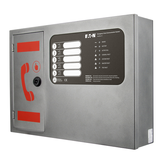
Eaton VoCALL 5 Installation And Operation Manual
Line exchange unit
Hide thumbs
Also See for VoCALL 5:
- Quick install manual (2 pages) ,
- Quick start manual (2 pages) ,
- Quick install manual (2 pages)
Table of Contents
Advertisement
Quick Links
Advertisement
Table of Contents

Related Manuals for Eaton VoCALL 5


Summary of Contents for Eaton VoCALL 5
- Page 1 VoCALL 5 Line Exchange Unit Installation and Operation Manual...
-
Page 2: Table Of Contents
5. ConnECtInG VoCALL 5 ........ - Page 3 WArnInG this unit must be earthed WArnInG Each compact unit requires a 3A fused spur, returning to a breaker clearly marked EVCs do not tUrn oFF. InstALLAtIon And opErAtIon MAnUAL 25-13400-C May 2019 www.eaton.com...
- Page 4 WEEE directive. doCUMEnt UpdAtE notEs S.No. Release / Change Notes Date Revision 3 May 2019 InstALLAtIon And opErAtIon MAnUAL 25-13400-C May 2019 www.eaton.com...
-
Page 5: Introduction
Emergency Assistance Alarms. VoCALL 5 is designed to fully comply with BS5839-Part 9 for use as a fire telephone system, disabled refuge call system or as a combined system when both fire telephones and disabled refuge points are required. -
Page 6: Unpacking The Unit
2. Unpacking the Unit 2. Unpacking the Unit Remove the VoCALL 5 EVCS unit from its packing, and check the contents against the following: 1. VoCALL 5 EVCS unit 2. Quick Start Guide 3. Accessory pack with the following contents:- a. -
Page 7: Mounting Vocall 5
4. Mounting VoCALL 5 4. Mounting VoCALL 5 Before mounting the VoCALL 5 on the wall it is advisable to remove the cable knockouts. Unused knockouts must be left unopened to comply with the Low Voltage Directive (LVD), accidentally knocked out holes should be blanked off. -
Page 8: Stainless Steel Flush Mount (Efvcc5-Fc)
4.2 Stainless Steel Flush Mount (EFVCC5-FC) If the VoCALL 5 is to be fitted with the Stainless Steel Flush Mount option (EFVCC5-FC), the dimensions of the hole cut into the wall must only exceed the dimensions of the panel by a maximum of 20mm on all sides. -
Page 9: Semi-Flush Bezel (Efvcc5-Fb)
4.3 Semi-Flush Bezel (EFVCC5-FB) If the VoCALL 5 is to be fitted with the semi-flush bezel option (EFVCC5-FB), the dimensions of the hole cut into the wall must only exceed the dimensions of the panel by a maximum of 20mm on all sides. -
Page 10: Connecting Vocall 5
You must observe local wiring regulations. Do not run SELV and LV cables in the same enclosure without adequate insulation between them. 5.2 Mains Connection Each VoCALL 5 requires a 3A fused spur, returning to a breaker clearly marked “EVCS DO NOT TURN OFF” . InstALLAtIon And opErAtIon MAnUAL 25-13400-C May 2019 www.eaton.com... -
Page 11: Vocall 5 Wiring
5.5 Cable Type All cables on the VoCALL 5 system should be of a type required to comply with local regulations. The unit will work with MICC to 200m per line and enhanced Soft Skin cables to 500m per line. -
Page 12: Outstation Wiring (Type A)
Network / VoCALL 5 Min 1mm CSA 2 core soft skinned Line + Connector on Network / VoCALL 5 to Type B line + Line - Connector on Network / VoCALL 5 to Type B line - Figure 7. type B outstation Connection 6. -
Page 13: Remote Disarming/Arming - Fault/In-Use
3rd party systems such as a fire alarm system. It is a useful feature when the VoCALL 5 is located in a public area and unwanted use needs to be controlled. -
Page 14: Battery Fitting
7. Batteries 7.1 Battery fitting Figure 9. Inserting the batteries (not included) 7.2 Battery wiring Figure 10. Wiring the batteries (not included) InstALLAtIon And opErAtIon MAnUAL 25-13400-C May 2019 www.eaton.com... -
Page 15: Safety Information
Disconnect the batteries before removing the mains power; always remove the negative (Black – terminal) first. 8. Operation All conversations on the VoCALL 5 system are under the command of the control handset. 8.1 Receiving a call at the main panel Lift the receiver;... -
Page 16: Accepting Faults
Outstation zone fault Indicators (Red) Active Call Call in progress Zone Handset Symbol: - Master Calling Zone Quick Flash - Zone Calling Master Quick Flash - During Call Solid - Holding Call Slow Flash InstALLAtIon And opErAtIon MAnUAL 25-13400-C May 2019 www.eaton.com... -
Page 17: Maintenance
Engineer Call to check system operation and check battery health. 5 Yearlye: Engineer Call to check system operation and replace the batteries. Different maintenance schedules may be required in different countries, please check your local standards. InstALLAtIon And opErAtIon MAnUAL 25-13400-C May 2019 www.eaton.com... -
Page 18: Technical Specification
303mm x 433mm x 89mm EFVCC5-FC 353mm x 483mm x 2.5mm EFVCC5-FB 359mm x 490mm x 0.9mm Weight EFVCC5 5.45kg (without batteries) EFVCC5 with EFVCC5-FC fitted 7.63kg (without batteries) EFVCC5 with EFVCC5-FB fitted 6.05kg (without batteries) InstALLAtIon And opErAtIon MAnUAL 25-13400-C May 2019 www.eaton.com... - Page 19 InstALLAtIon And opErAtIon MAnUAL 25-13400-C May 2019 www.eaton.com...
- Page 20 South Yorkshire DN2 4NB Eaton EMEA Headquarters Route de la Longeraie 7 1110 Morges, Switzerland Eaton.eu © 2019 Eaton Eaton is a registered trademark. All Rights Reserved Publication No. 25-13400-C All trademarks are property May 2019 of their respective owners.
Need help?
Do you have a question about the VoCALL 5 and is the answer not in the manual?
Questions and answers