Advertisement
Quick Links
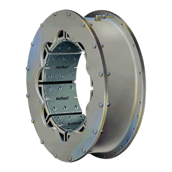
VC 5000
Installation, Operation
and Maintenance of
®
Airflex
VC Element
Assemblies
Forward this manual to the person responsible
for Installation, Operation and Maintenance of
the product described herein. Without access
to this information, faulty Installation, Operation
or Maintenance may result in personal injury or
equipment damage.
Use Only Genuine Airflex
Airflex Division of Eaton Corporation recommends the use of
genuine Airflex replacement parts. The use of non-genuine Airflex
replacement parts could result in substandard product performance,
and may void your Eaton warranty. For optimum performance, contact
August, 1989
(Revised: July, 1995)
203675
© Copyright Eaton Corp., 1995. All rights reserved.
PDF Format
Warning
Caution:
®
Replacement Parts
The
Advertisement

Related Manuals for Eaton Airflex VC 5000


Summary of Contents for Eaton Airflex VC 5000
- Page 1 Airflex Division of Eaton Corporation recommends the use of genuine Airflex replacement parts. The use of non-genuine Airflex replacement parts could result in substandard product performance, and may void your Eaton warranty. For optimum performance, contact August, 1989 (Revised: July, 1995) 203675 ©...
- Page 2 FIG. I- COMPONENT PARTS FOR AIRFLEX TYPE VC ELEMENT Optional Muffler for Release Valve DESCRIPTION Tube (w/valve stem snap rings where req’d.) Elbow Assembly Optional - Quick Release Valve Assembly Compression Ring (included-with items 3 & 3A) Air Connection Tube Air Connection Gasket Friction Shoe Assembly Air Tube Group fDual Mounted)
-
Page 3: Hazard Warnings
1.0 INTRODUCTION 1.1.4 Where diametral space is limited, or the torque required is greater than a single element can transmit, all sizes of Airflex VC elements can Throughout this manual there are a number of be supplied as dual units. HAZARD WARNINGS that must be read and adhered to in order to prevent possible per-... -
Page 4: Installation
FRICTION SHOE ASSEMBLY WITHDRAWN Pressure Source Tube Drum Surface - Side Plate WITH DRUM Actuating Air Pressure Tube (Inflated) Release Spring (Compressed) r, Contact / With Drum Fig. 2 2.0 INSTALLATION Mounting Arrangements 2.1.1 Figure illustrates the gap-mounting arrange- ! Warning: ment. - Page 5 SINGLE NARROW & SINGLE WIDE Device Fig. DUAL NARROW Outboard Element Brake Reaction DUAL WIDE Outboard Bracket Fig. 5 Element Figure 6 illustrates a typical marine main 2.1.4 propulsion application. In this arrangement, the element is attached to a pinion adapter plate and the drum and drum hub are attached to a quill shaft.
-
Page 6: Mounting Considerations
2.2.2 The element must be protected from con- 2.15 Figure 7 illustrates a typical marine main tamination from oil, grease or excessive propulsion application where the clutch is amounts of dust. mounted between the engine and reduction gear. In this arrangement, the VC clutch is combined with a Geislinger* flexible torsional ! Caution: coupling. - Page 7 TABLE 1 - FASTENER ASSEMBLY TORQUE SN = SINGLE NARROW SW = SINGLE WIDE DN = DUAL NARROW DW = DUAL WIDE L = LUBED TORQUE - FT.-LB. (Nm) (30 WT. MOTOR OIL OR ANTI-SEIZE) D = DRY TORQUE - FT.-LB. (Nm) ELEMENT TO SPIDER/ SIZE SIDE PLATE TO RIM...
- Page 8 2 4 . Shaft Alignment 2 3 . Mounting Spider and Drum Hub 2.3.1 Note: The text in this section applies to gap- The spider and drum hub are bored for a mounted applications; however, the alignment press fit onto their respective shafts. The inter- tolerances apply to all types of mountings.
- Page 9 2.4.6 Shim and shift the base of the movable shaft to correct the misalignment. After tightening the base, recheck the alignment and correct if necessary. Make sure to check for a “soft foot” condition. Dowel or chock into position after satisfactory alignment has been achieved.
- Page 10 TABLE 3 - AIR CONNECTIONS FOR VC ELEMENTS OLD METHOD CURRENT METHOD (FLANGED TUBE) (STRAIGHT TUBE) SIZE AIR TUBE WASHER AIR TUBE WASHER 2 0 1 4 0 2 7 2 x 1 5 4 1 2 1 7 8 - 0 2 4 1 2 3 2 4 - 0 1 1 4 V C 5 0 0 2 0 1 3 0 2...
- Page 11 Air Control System Rubber 2.7.1 A typical air control system is shown on Sleeve Figure 12. Since the air control system used will be dependent on the specific application, Long a detailed description cannot be made in this Air Tube manual.
- Page 12 TABLE 4 - MAXIMUM SAFE OPERATING SPEEDS Size (Wide) Size (Narrow) Maximum RPM Size (Narrow) Maximum RPM Maximum RPM Size (Wide) Maximum RPM 28VC650 1000 14VC1000 1800 42VC1200 11.5VC500 1800 14VC500 1500 33VC650 16VC1000 1400 46VC1200 16VC600 1400 35VC650 20VC1000 1300 52VC1200 24VCl000...
- Page 13 4.1.2 Partial or complete disassem bly is required to TABLE 5 inspect the following items: FRICTION MATERIAL THICKNESSES 4.1.2.1 NARROW SERIES Drum Diameter Wear - Check the O.D. of the Minimum Original Lining drum and compare to the values shown on Element Allowable Lining Thickness,...
- Page 14 4.1.2.8 4.1.2.3 Friction Shoe Lining Wear - If the linings are Contamination of Friction Shoes - Mild oil or glazed, they may be lightly sanded to remove grease contamination may be removed with a the glazing PROVIDING THEY DO NOT CON- solvent.
- Page 15 4 5 . Disconnect the dual element from the spider Disassembly of the Element 4.3.2 and allow it to rest on the drums. Remove the air connection tubes. 4.5.1 the element flat on a clean work surface. Remove the fasteners and spacers attaching 4.3.3 Remove the side plate and clean for reassemb- 4.5.2...
- Page 16 4.7.4 Carefully insert the air actuating tube into the 4 6 . Friction Lining Replacement rim. Push the valves on the tube through the corresponding holes in the rim and install the Caution: spiral snap rings (if applicable). Use only genuine Airflex replacement 4.7.5 Place a torque bar in each mating hole in the parts.
- Page 17 6.0 ORDERING INFORMATION/ 5 0 . SPARE PARTS STORAGE TECHNICAL ASSISTANCE 51 . Element Assemblies 61 . Equipment Reference 5.1.1 Element assemblies must always be stored flat. Storage in the standing position may 6.1.1 In any correspondence regarding Air-flex equip- cause the rims to go out-of-round.
- Page 20 105904 142647HA 42VC650 Quick Release Valves 2 Req’d Element with four 142121C 105812A 105904 Side Connections Element with four 142121D 105812C 105904 Quick Release Valves VC 5000 Revised: July, 1995 (PDF Format) © Copyright Eaton Corp., 1989. All rights reserved.
- Page 23 142835HA 105892A 105910 51VC1600 2 Req’d 142132AL 142915MB 105894A 105911 60VC1600 2 Req’d 142198C 142097HA 105897A ---- 66VC1600 2 Req’d All elements are dual drilled. VC 5000 Revised: July, 1995 (PDF Format) © Copyright Eaton Corp., 1989. All rights reserved.
-
Page 24: Repair Kits
146236F 32VC1000 146237F 33VC650 146236G 38VC1200 146237G 35VC650 146236H 42VC1200 146237H 37VC650 146236J 46VC1200 146237J 42VC650 146236K 52VC1200 146237K 51VC1600 146237L 60VC1600 146237M 66VC1600 146237N VC 5000 Revised: July, 1995 (PDF Format) © Copyright Eaton Corp., 1989. All rights reserved. - Page 25 (12) months from the date of SPECIFICALLY EXCLUDED. shipment to Purchaser, provided such Product is properly installed, properly maintained, operated under normal In no event shall Eaton be liable for conditions with competent special, incidental or consequential supervision. Warranty claims shall be damages.
Need help?
Do you have a question about the Airflex VC 5000 and is the answer not in the manual?
Questions and answers