
Related Manuals for Chromalox MicroTherm


Summary of Contents for Chromalox MicroTherm
- Page 1 Installation & Operation Manual Circulating Oil Temperature Control System PQ451 161-123417-037 February 2019...
-
Page 2: Table Of Contents
Table of Contents Contents Page Number Section 1 Getting Started ............................1 Section 2 Installation .............................. 4 Section 3 Temperature Control ..........................7 Section 4 Operation ............................... 8 Section 5 Diagnostics ............................9 Section 6 Maintenance ............................10 Section 7 Troubleshooting ........................... 13 Section 8 Specifications ............................ -
Page 3: Section 1 Getting Started
Oil or other synthetic fluids or mineral based fluids may The microTHERM™ Oil can be operated at a maximum be used with this product. See section 4 number 1. temperature of 550°F. Oil temperature is maintained by... -
Page 4: System Photo
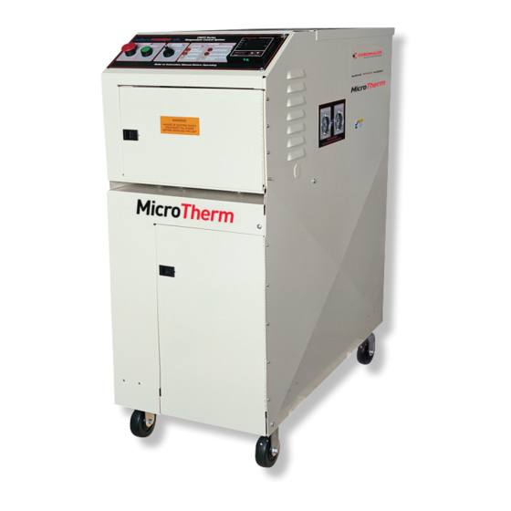
Figure 1.1 System Photo (Side View) Operating temperatures of Steel sheath chromalox 50˚ to 550˚F for a wide vari- heating elements ety of applications 3.2 sq. ft. heat exchanger for cooling integral with heating chamber. ASME safety relief valve opens if water pressure exceeds 125 psi, ensuring safe operation. -
Page 5: Control Panel
Figure 1.2 Control Panel CMXO Series OIL Temperature Control System Manual Cooling Switch Pump START/STOP Pushbuttons Status and Diagnostic Indicators Chromalox Temperature and Process Controller. (Controller model supplied may vary from picture) -
Page 6: Section 2 Installation
Section 2 – Installation Before Hydraulic Installation: Do not place valves in vent line or allow vent line to become even partially clogged. Vent line Before proceeding with the installation please take on the expansion tank must be piped to a safe note of the following information: area and/or catch drum. -
Page 7: Piping
Figure 2.1 Piping VENT SAFETY RELIEF VALVE TO SAFE AREA Figure 2.2 Piping Connections 18.6 OIL/OUTLET 1-1/2" NPT HEATER DRAIN 1/2" COOLING WATER/INLET 1/2" NPT COOLING WATER/OUTLET 1/2" 45.1 OIL/INLET 1-1/2" 22-3/8 3-3/4 6-1/4... -
Page 8: Power Connection Terminals
Hydraulic Installation Pump Rotation Check 5. Close the front electrical enclosure door. Pull the HAZARD OF ELECTRIC SHOCK. Disconnect all top cover off of the heat transfer system and locate power before installing or servicing the heat the pump motor. transfer system. -
Page 9: Section 3 Temperature Control
Section 3 – Temperature Control Options Figure 3.1 Control Panel Layout Outlet Pressure “To Process” Inlet Pressure “From Process” CMXO Series OIL Temperature Control System START/STOP Pushbuttons Status and Diagnostic Indicators Temerature Controller System shuts down if any red diag- Press to start the pump. -
Page 10: Section 4 Operation
Section 4 – Operation lem persists, drain the system and recharge with new moisture-free heat transfer liquid. Damage to the pump and/or heater may occur 9. After the system is completely free of air pockets if the system is operated without fluid. Fill sys- and moisture, set control thermostat at the desired tem prior to starting. -
Page 11: Section 5 Diagnostics
CMXO Series OIL Section 5 – Diagnostics Temperature Control System ELECTRIC SHOCK HAZARD. Close the front electrical enclosure door and retighten the locking screw. This must be done to limit ac- cess to high voltage components. Failure to comply could result in personal injury or equip- ment damage. -
Page 12: Section 6 Maintenance
Section 6 – Maintenance ELECTRIC SHOCK AND BURN HAZARD. Discon- BURN HAZARD. Never service system while nect all power before servicing or performing hot. Allow system to cool to room temperature maintenance to the system. Do not attempt to before servicing. service system while it is operating or while 1. - Page 13 Pump Removal/Replacement 7. Service pump per pump manufacturers instruc- tions. ELECTRIC SHOCK HAZARD. Disconnect all 8. If replacing the pump, be sure to remove piping power to system before servicing. Failure to from old pump casing before discarding. Clean comply can result in personal injury or equip- thread on pipe and thread into new pump casing ment damage.
- Page 14 Maintenance Record Date Maintenance Record...
-
Page 15: Section 7 Troubleshooting
4. Check factory MENU settings, Section 3 of this manual. Refer to 2104 Controller Techni- cal manual, page 35, for further information. If you continue to have problems with the system after review of the above issues, please contact Chromalox Product Service at 800-443-2640. -
Page 16: Section 8 Specifications
Section 8 – Specifications Pump Size Nominal Flow Oil Connections Water Approximate Dimensions (HP) (gpm) (Inches, dia.) (Inches, dia.) (Inches) 1-1/2 NPT 1/2 NPT 45H x 38D x 19W Cubic Meters Per Hour Meters 3 HP U.S. Gallons Per Minute Figure 8.1 - Pump Capacity (As reported by pump manufacturer on Model HTO-80;... -
Page 17: Replacement Parts Identification
Figure 8.2 - Replacement Parts Identification 7 or CAUTION-DO NOT SET TEMPERATURE ABOVE 600˚F SCR PWR CONTROLLER OPTIONAL CONNECT ____VOLT SUPPLY HERE... - Page 18 Over Temperature Controller 381-700400-297 112-121869-005 300-400360-610 On/Off Cooling Switch 292-304687-002 Limited Warranty: Please refer to the Chromalox limited warranty applicable to this product at http://www.chromalox.com/customer-service/policies/termsofsale.aspx. Chromalox, Inc. 2150 N. Rulon White Blvd., Ogden, UT 84404 Phone: 1-800-368-2493 www.chromalox.com © 2019 Chromalox, Inc.
Need help?
Do you have a question about the MicroTherm and is the answer not in the manual?
Questions and answers
is there a maintainance checklist
Yes, there is a maintenance checklist for the Chromalox MicroTherm system. It includes the following steps:
1. Disconnect power from the system and remove wiring to the heater.
2. Disconnect the thermocouple from the control cabinet.
3. Drain the heater and pump.
4. Remove bolts on the heater and undo pipe fittings. Remove the heater through the front door.
5. Install a new heater and retighten all bolts and fittings.
6. Reattach all sheet metal and retighten screws.
7. Refill the system and follow the operation procedure in Section 4.
Maintenance must be done by qualified personnel only.
This answer is automatically generated