Table of Contents
Advertisement
Quick Links
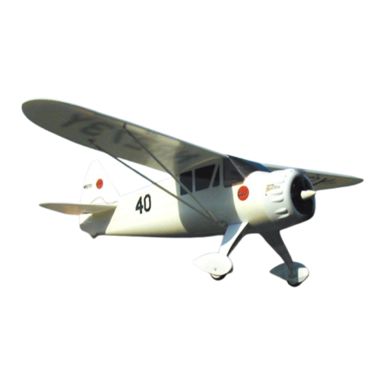
No.4321 Mr. Mulligan
Wing Span: 39.37" (1000mm)
Wing Area:217 sq.in. (14dm
This kit is guaranteed to be free from defects in material and workmanship at the date of purchase.
It does not cover any damage caused by use or modification. The warranty does not extend beyond
the product itself and is limited only to the original cost of the kit. By the act of building this user-
assembled kit, the user accepts all resulting liability for damage caused by the final product. If the
buyer is not prepared to accept this liability, it can be returned new and unused to the place of
purchase for a refund.
This is not a toy. Assembly and flying of this product requires adult supervision. Read through this
book completely and become familiar with the assembly and flight of this airplane. Inspect all parts
for completeness and damage. Contact Thunder Tiger authrized distriburtor for help.
Length: 26.5" (675mm)
)
Weight: 16.5 oz. (470g)
2
Warranty
Notice: Adult Supervision Required
1
Advertisement
Table of Contents

Related Manuals for THUNDER TIGER Mister Mulligan 4321


Summary of Contents for THUNDER TIGER Mister Mulligan 4321
- Page 1 This is not a toy. Assembly and flying of this product requires adult supervision. Read through this book completely and become familiar with the assembly and flight of this airplane. Inspect all parts for completeness and damage. Contact Thunder Tiger authrized distriburtor for help.
-
Page 2: Table Of Contents
I I N N T T R R O O D D U U C C T T I I O O N N All of us at Thunder Tiger want to thank you for choosing the Mr. Mulligan EP park flyer. -
Page 3: Pre-Assembly Notes
Medium Grit Sandpaper Radio: You will need at least a 3 channel radio control system with 2 micro servos for your Mr. Rubbing Alcohol Mulligan. Thunder Tiger provides 3ch sigle- Paper Towel stick(8304) and dual-stick(8305) for choice. Hobby Knife Drill bit 5/64” (2mm) -
Page 4: Part Drawings
PART DRAWINGS Open the box and check that you have all the parts as shown below. If anything is missing please contact your dealer. AS6325 Fuselage AS6331 Cowling Landing Gear Fuselage(L/1, R/1) Retainer (1) Cowling (1) Skid (1) Landing Gear Mount(1) Box Cover(1) Wood Block(3) Front Wing Mount(1) -
Page 5: Assembly Fuselage
ASSEMBLY / FUSELAGE glue it in place with furnished epoxy. Hint: How to tell the left or right of the fuselage? You can image you are sitting in the cockpit then the right fuselage is at right side. 1. Locate firewall and cowling mounts B & C. 5. - Page 6 ASSEMBLY / FUSELAGE 90˚ 8. Epoxy left and right fuselage halves together. 11. Note the ring of wing strut mount should be Note the furnished epoxy is 5-min. epoxy and perpendicular to the line as illustrated. working time is only 3 min., you will have to quickly apply epoxy on left and right fuselage within 3 minutes.
-
Page 7: Tail
ASSEMBLY / TAILS 19. Locate elevator pushrod(the short one), insert 15. Glue the cut away portion on rudder as shown. the pushrod from front fuselage through the You may trial fit the portion on the rudder first. pushrod support and exit at the tail. Thread the Note the leading edge of this portion should clevis then snap onto the elevator joiner. -
Page 8: Landing Gear
ASSEMBLY / LANDING GEAR 27. Trim the wheel pant as shown and drill 4mm holes for wheel axle. 23. Install the rudder control horn. Make sure the control horn is installed properly before you press in the locking plate and do not over press the locking plate. -
Page 9: Cowl
ASSEMBLY / COWL engines and trim away the excess. This is to get more air to cool down the hot battery and motor. 31. Locate the EDS( electric drive system) and remove the spinner and nuts. Note: remove the nose cone by rotating it counter-clockwise about 35. -
Page 10: Servo, Esc, Rx & Battery
SERVO, ESC,RX & BATTERY INSTALLATION Receiver inside the fuselage. Drill a small hole on the fuselage at right side then thread the antenna through the fuselage. Route the antenna to the tail and tape it in place. 38. See the servo manual and install the eyelet and grommet then secure the micro servos in the servo tray with the wood screws that comes with 42. -
Page 11: Wing
ASSEMBLY / WING 50. Assemble the wing strut joiner as shown, you will need to thread the threaded rod to the wing strut joiner first then thread the clevis. A needle nose pliers will help thread the rod. Epoxy the two 46. -
Page 12: Balance
OPERATION CHECK 1. Install eight AA batteries in the transmitter, referring to the radio system’s instruction manual. 2. Review the illustration to become familiar with your airborne radio components. Following are description of these components: ESC: This device controls power to the motor unit. - Page 13 CHECK THE RADIO THE DIRECTION OF MOVEMENT (RUDDER AND ELEVATOR) NEUTRAL RIGHT TURN LEFT TURN Check the position of rudder and elevator (if these are in neutral). Set the trim in neutral position. Move the stick to the left. Move the stick to the right. Set the sticks in neutral position DOWN RIGHT AND UP...
-
Page 14: Flying
FLYING Usually, only small stick movements are required. FLYING Try to keep your flying smooth. You can turn the plane by bumping small amounts of rudder and You should have a flight instructor to teach you how to then return to neutral. Use the elevator to keep fly the Mr. - Page 15 FLYING Incorrect Wind Direction Correct Straight and level with ground Launch firmly into wind straight and level. Do not throw upwards! Launch Example of a turn using only rudder Example of a turn using rudder then elevator Wind Landing Wind Direction 3 ft.
-
Page 16: Repair
Tiger be your chosen brand, no matter what to their full length. Make sure the transmitter direction you progress. batteries are fresh. Make sure no one else is operation on your channel(frequency) in the THUNDER TIGER CORPORATION http://www.thundertiger.com JE6690...
Need help?
Do you have a question about the Mister Mulligan 4321 and is the answer not in the manual?
Questions and answers