Market Forge Industries STM-ED Owner's Manual
Electric sterilmatic steriiizer
Hide thumbs
Also See for STM-ED:
- Operation, service manual & parts list (14 pages) ,
- Installation & operation manual (24 pages)
Table of Contents
Advertisement
OWNER'S MANUAL
E L E C T R I C S T E R I L M A T I C S T E R I L I Z E R
E L E C T R I C S T E R I L M A T I C S T E R I L I Z E R
DOMESTIC MODEL:
H-2117
FORM NO.:
03/14
REV. A
DIGITAL VERSION
□
STM-ED
EXPORT MODEL:
•
INSTALLATION
•
OPERATION
•
MAINTENANCE
•
TROUBLE-SHOOTING
•
PARTS & SERVICE
•
WARRANTY
35 Garvey Street, Everett, MA 02149
Sterilizers.com - Your Sterilizer Expert
Distribution – Maintenance - Guaranteed
Telephone: (617) 387-4100, (866) 698-3188
Alfa Medical - 10 Bond St Great Neck NY 11021
Fax: (617) 387-4456, (800) 227-2659
1-800-762-1586 - info@Sterilizers.com
custserv@mfi i.com, www.mfi i.com
□
STM-EDX
Advertisement
Table of Contents

Related Manuals for Market Forge Industries STM-ED


Summary of Contents for Market Forge Industries STM-ED
- Page 1 E L E C T R I C S T E R I L M A T I C S T E R I L I Z E R DIGITAL VERSION □ □ DOMESTIC MODEL: STM-ED EXPORT MODEL: STM-EDX • INSTALLATION •...
-
Page 2: Table Of Contents
Vent Piping ...............23 Wiring Diagram - 1 Phase ..........5 Electrical Components............24 Wiring Diagram - 3 Phase ..........6 Sterilizer Assembly ............25 Typical Circuit Connection for STM-ED ......7 Pan Supports & Baffle ............26 Door Handle Assembly .............27 SECTION 2 WATER CONDITIONS Water Conditions ..............9 SECTION 7 TROUBLE-SHOOTING Trouble Shooting Guide ............29... -
Page 3: Introduction
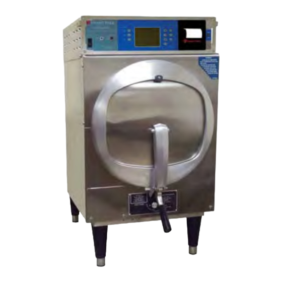
INTRODUCTION Product Description: The Market Forge Sterilmatic Sterilizer with Digital Controller (model STM-ED) is a compact, automatic, low cost steam pressure sterilizer (autoclave). The sterilizing cylinder is a 3/16” (4.8mm) thick wall, welded aluminum. The exterior is made of polished stainless steel. -
Page 4: Section 1 Installation Instructions
AUTOMATIC STERILMATIC STEAM forward 1/4” (6mm) to insure positive drainage of the PRESSURE STERILIZER cylinder. MODELS: STM-ED, & STM-EDX ELECTRICAL SERVICE & TECHNICAL INFORMATION CONTACT Connect to proper electrical supply box and disconnect switch as shown on one of the following schematic dia- NOTE: This unit should be serviced by qualified grams - 208 or 240 volts, single or three phase. -
Page 5: Cold Water Condenser
SECTION 1 INSTALLATION INSTRUCTIONS DEIONIZED WATER. COLD WATER CONDENSER Close chamber door. PART QTY. ITEM DESCRIPTION Set exhaust selector to INSTRUMENTS AND 95-2119 Steam condensing unit PACKS (fast exhaust) or LIQUIDS (slow exhaust). 95-2219 Thermostat Box Assy. Set timer to 15 minutes. Cycle will go to completion 95-0086 Exhaust line automatically. -
Page 6: Electrical Requirements
208-240V, 4 Wire, 3 Phase, 60 Hz □ 220V, 1 Phase, 50 Hz □ 220V, 3 Phase, 50 Hz AMP/PHASE Single Phase Three Phase DOMESTIC MODEL 208V 240V 208V 240V STM-ED 12.4 Single Phase Three Phase EXPORT MODEL 220V 240V 220/380V 240/415V 10.4 STM-EDX 12.4 •... -
Page 7: Instructions For Installing Pan Supports & Baffles
THE ELECTRIC SUPPLY CONNECTIONS FOR STM-ED: Connect to proper electrical supply as indicated on nameplate on top of unit. The power supply cord is brought in from the rear of the unit, through the conduit and the connection is made at the terminal box located at the front of the unit. -
Page 8: Wiring Diagram - 1 Phase
SECTION 1 INSTALLATION INSTRUCTIONS AMPs Per Line Wire Volts Phase 10.4 10.4 12.4 12.4 WIRE BLU 18 GA... -
Page 9: Wiring Diagram - 3 Phase
SECTION 1 INSTALLATION INSTRUCTIONS AMPs Per Line Wire Volts Phase 10.4 10.4 12.4 12.4 WIRE BLU 18 GA 22 WIRE ORG 18 GA... -
Page 10: Typical Circuit Connection For Stm-Ed
SECTION 1 INSTALLATION INSTRUCTIONS TYPICAL CIRCUIT CONNECTION FOR STM-ED STERILIZER FUSE AND ELECTRICAL SOURCE DISCONNECTED MEANS UNIT WIRING 240 Volt, 3 Phase 208 Volt, 3 Phase 240 Volt, 1 Phase 208 Volt, 1 Phase... - Page 11 SECTION 1 INSTALLATION INSTRUCTIONS TYPICAL CIRCUIT CONNECTION FOR STM-EDX STERILIZER -EXPORT- FUSE AND ELECTRICAL SOURCE DISCONNECTED MEANS UNIT WIRING 4- Wire, 3 Phase Delta (480/240V) This page intentionally left blank. 4- Wire, Wye Connected 380/220V, 3 Phase 4- Wire, Wye Connected 415/240V, 3 Phase...
-
Page 12: Water Conditions
Market Forge from time to time is asked the question about using distilled or deionized water for use with our Sterilizer models STM-ED and STM-EDX. We are always asked why these water choices are not allowed for use with our units and what would be recommended. To address this situation, we have complied the following as a... -
Page 13: Section 3 Operating Instructions
SECTION 3 OPERATING INSTRUCTIONS position. This will allow steam and moisture to es- GENERAL OPERATING INSTRUCTIONS: cape. Allow door to remain in this position for 15 Make sure the drain valve is closed. IMPORTANT: to 20 minutes before removing load. Small packs Fill bottom of the sterilizer chamber with approxi- can be dried successfully with this procedure. -
Page 14: Minimum Sterilization Times Table
SECTION 3 OPERATING INSTRUCTIONS MINIMUM STERILIZATION TIMES TIME (Minutes) ARTICLES Glassware, empty, inverted. • Instruments, metal in covered or open tray, padded or unpadded. • Needles, unwrapped. • Pipettes, blood diluting, serological, volumetric, etc • Tubing glass (6mm), (10mm) inverted •... -
Page 15: Control Panel
SECTION 3 OPERATING INSTRUCTIONS DETAILED OPERATING INSTRUCTIONS Before operating this unit be sure to have read the Owner’s manual for proper setup, service connections and installation. In addition, the Owner’s manual will cover sterilization recommendations, daily cleaning procedures and parts lists. Control Panel Identification IITEM DESCRIPTION... -
Page 16: Controller Overview
SECTION 3 OPERATING INSTRUCTIONS Controller Overview The Digital Controller is made up of the Operational Keys, Digital LCD Display and the Data Logger/Printer. The operator can set the controller to display in either degrees Fahrenheit (°F) with pressure in PSI or in degrees Celcius (°C ) with pressure in kPa. -
Page 17: Setting Time
SECTION 3 OPERATING INSTRUCTIONS ▫ Press and hold the TEMP key until the display goes blank and shows only the temperature. Now press the appropriate UP or DOWN key to get to desired set-point. ▫ When the full display returns the target set-point has been set. ●... -
Page 18: Preset Keys
SECTION 3 OPERATING INSTRUCTIONS door to allow the chamber to cool. NOTE: There is never any harm in releasing the chamber door latch. If there is pressure inside the cham- ber the door cannot open due to its design which does not allow the door to open under pressure. Preset Keys There are three PRESET keys numbered 1, 2 &... -
Page 19: Print Key
SECTION 3 OPERATING INSTRUCTIONS Also included at the end of each printout is the following; Example: DATE: OPERATOR: The DATE, OPERATOR and COMMENTS fields can be hand written in if COMMENTS: required. ● PRINT Key ▪ In the LCD Display, if the word PRINT is displayed then the recorded data will be automatically printed at the end of the full sterilization cycle. -
Page 20: Low Water Reset
SECTION 3 OPERATING INSTRUCTIONS Low Water Reset If the water inside the chamber is allowed to run dry it will trigger the Low Water Cut-off. At this point the unit will; ▫ Shut down all three heating elements ▫ Light the red Low Water indicator light. ▫... -
Page 21: Section 4 Maintenance
SECTION 4 MAINTENANCE DAILY CLEANING PROCEDURE (AT THE END OF EACH DAY): Remove bottom splash baffle. NOTE: IMPORTANT! STERILIZING CHAMBER MUST BE CLEANED AND DRAINED DAILY US- ING THE FOLLOWING PROCEDURE. WASH WETTED PORTION OF THE CYLINDER THOR- OUGHLY BY ADDING A MILD DETERGENT TO WATER IN CYLINDER. If a soft cloth or brush is used with the detergent and does not completely remove the surface film, a nylon soap pad should be used. -
Page 22: Section 5 Field Service Instructions & Assembly
SECTION 5 FIELD SERVICE INSTRUCTIONS & ASSEMBLY STERILMATIC OPEN STAND: Market Forge Sterilmatic Stand can be supplemented with an Optional Stand for utility use where maxi- mum compactness is desired. The sturdy, stainless steel unit is equipped with adjustable leg ex- tensions which allow the unit to be installed and leveled over existing contours in the floor. -
Page 23: Door Assembly
SECTION 5 FIELD SERVICE INSTRUCTIONS & ASSEMBLY DOOR ASSEMBLY ITEM PART NO. DESCRIPTION Pivot Spring Bearing 10-6765 Right and Left Door Spring (sold as a pair) 91-2718 10-32 Machine Screw 1/2” Long 10-1776 Door Gasket 10-2666 Door & Door Spring Assembly 95-3204 Items 1 through 5 95-0124... -
Page 24: The Fulcrum & Drain Assembly
SECTION 5 FIELD SERVICE INSTRUCTIONS & ASSEMBLY THE FULCRUM & DRAIN ASSEMBLY: The fulcrum and drain assembly is located at the lower front of the sterilizing chamber and furnishes a sturdy anchorage for the door locking system of the door handle. Also provided in this assembly is a means for ad- justment of the door seal. -
Page 25: Cast-In Heating Elements
SECTION 5 FIELD SERVICE INSTRUCTIONS & ASSEMBLY CAST-IN HEATING ELEMENTS: Located under the sterilizing cylinder is a bank of (3) U-shaped heating elements. These elements are welded in place in a protective aluminum shield. The elements cannot be removed, and in the unlikely event that one or all fail, the complete cylinder must be replaced. -
Page 26: Section 6 Illustrated Parts List
SECTION 6 ILLUSTRATED PARTS Vent Piping View ITEM PART NO. DESCRIPTION QTY. Exhaust Solenoid Valve, 220/240 Volts 10-0938 90° Street Elbow, Brass, ½” IPS, (reworked) 95-3730 Safety Valve, 17 lbs 10-7942 Heat Sink 90° Street Elbow, Brass, 1/2” NPT 10-2863 1/2”... -
Page 27: Electrical Components
SECTION 6 ILLUSTRATED PARTS Electrical Components, Open Top View, Rear Electrical Components, Open Top View, Front ITEM PART NO. DESCRIPTION QTY. Contactor, 240V, 75 Amp 09-6484 Solid State Relay, 50 Amp Contactor, 2 Pole Axial Fan, 230V Printer Controller Board Low Water LED Low Water Cutoff 10-5990... -
Page 28: Sterilizer Assembly
SECTION 6 ILLUSTRATED PARTS Sterilizer Assembly ALL MODELS ITEM DESCRIPTION QTY. PART NO. Flue Cover Assy. 95-2558 Flue Outer Case Wrap 95-2652 Upper Case, Front 95-2650 Lower Case, Front 95-2616 Insulation, Body 10-6363 Insulation, Back 10-6365 Insulation, Bottom 10-6364 Bottom Cover for Elements 95-0465 95-2628 Cylinder, 208V - 240V (Shown with Door Assy.) -
Page 29: Pan Supports & Baffle
SECTION 5 FIELD SERVICE INSTRUCTIONS & ASSEMBLY Pan Supports and Baffle ALL MODELS ITEM DESCRIPTION QTY. PART NO. Outside Case, Left Side 95-3196 Outside Case, Right Side 95-3195 Outside Case, Back 95-3194 Handle Bumper 10-0226 Terminal Box Cover 95-3484 Pan Rack, 1 Left & 1 Right 95-2545 Condensate Baffle, Upper 95-2637... -
Page 30: Door Handle Assembly
SECTION 6 ILLUSTRATED PARTS Door Handle Assembly... - Page 31 SECTION 6 ILLUSTRATED PARTS DOOR HANDLE ASSEMBLY ITEM PART NO. DESCRIPTION 10-2318 10-32 Acorn Nut #10 Shakeproof Lockwasher 10-2514 10-32 Machine Screw 1 3/8” Lg. 95-0571 Bearing Spacer 95-0120 Door Lock Casting 95-0136 3/8” Shakeproof Lockwasher 10-2517 Door Lock Knob 10-0050 Door Handle Casting 95-0134...
-
Page 32: Section 7 Trouble-Shooting
SECTION 7 TROUBLE-SHOOTING TROUBLE-SHOOTING GUIDE TROUBLE POSSIBLE CAUSE CORRECTION Sterilizer fails to operate at all Not installed correctly. Check wire diagram for correct hook Blown fuse. (no pressure build up). Contactor burned out. Replace fuse. If it blows, check that Wiring is defective. -
Page 33: Section 8 Appendix
SECTION 8 APPENDIX Error Codes When an error occurs such as a Low Water condition, an error number will be displayed on the Digital LCD Dis- play. Following is a list of the error numbers and their descriptions; ● Err 01 ▪... -
Page 34: Section 9 Warranty Information
STERILIZER (AUTOCLAVE) WARRANTY MODELS: STM-E, STM-ED, STM-EL, STM-EX*, STM-EDX*, and STM-ELX* We warrant to the original purchaser that the sterilizers manufactured by Market Forge Industries, Inc. will be free from defects in material and factory workmanship if properly installed and operated under normal conditions. -
Page 35: Sterilizer Warranty Resistration
SECTION 9 WARRANTY INFORMATION STERILIZER (AUTOCLAVE) WARRANTY DOMESTIC MODELS: STM-E (95-2678) STM-EL (95-3441) STM-ED (95-6300) EXPORT MODELS: STM-EX (95-2902) STM-ELX (95-2903) STM-EDX (95-6301) We warrant to the original purchaser that the sterilizers manufactured by Market Forge Industries, Inc. - Page 36 SECTION 9 WARRANTY INFORMATION STERILIZER (AUTOCLAVE) WARRANTY Disclaimer: MODELS: STM-E STM-EL Thank you for Submitting your Sterilizer Warranty Information. This info is just for our records. Your information will not be STM-EX (Export) sold. We may share your information with your local Market Forge Sales Representatives for information to respond to inquiries, inform you about products, services or events that are relevant to your sterilizer purchase.
Need help?
Do you have a question about the STM-ED and is the answer not in the manual?
Questions and answers