Table of Contents
Advertisement
Quick Links
Peracetic Acid Monitor
Home Office
Analytical Technology, Inc.
6 Iron Bridge Drive
Collegeville, PA 19426
Phone: 800-959-0299
610-917-0991
Fax:
610-917-0992
Email: sales@analyticaltechnology.com
O & M Manual
Model Q46-85
European Office
ATI (UK) Limited
Unit 1 & 2 Gatehead Business Park
Delph New Road, Delph
Saddleworth OL3 5DE
Phone: +44 (0)1457-873-318
Fax:
+ 44 (0)1457-874-468
Email: sales@atiuk.com
Advertisement
Table of Contents

Subscribe to Our Youtube Channel
Related Manuals for ATI Technologies Q46-85


Summary of Contents for ATI Technologies Q46-85
- Page 1 O & M Manual Model Q46-85 Peracetic Acid Monitor Home Office European Office Analytical Technology, Inc. ATI (UK) Limited 6 Iron Bridge Drive Unit 1 & 2 Gatehead Business Park Collegeville, PA 19426 Delph New Road, Delph Phone: 800-959-0299 Saddleworth OL3 5DE...
-
Page 2: Table Of Contents
Table of Contents PART 1 - INTRODUCTION ......... 4 6.23 Calibration Menu [CAL]......36 6.24 Configuration Menu [CONFIG] ....36 General ............4 Standard System ........5 6.25 Control Menu [CONTROL] ....41 6.26 Diagnostics Menu [DIAG] ......45 Features ............. 8 Q46/85 System Specifications ....9 PART 7 –... - Page 3 Table of Figures 1 - T ..................5 IGURE YPICAL YSTEM IAGRAM 2 - M ............ 6 IGURE ONITORING YSTEM W AYONET TYLE P NSOR 3 - S ............7 IGURE EALED LOWCELL SSEMBLIES W ONTROL 4 – Q46 E ..................
-
Page 4: Part 1 - Introduction
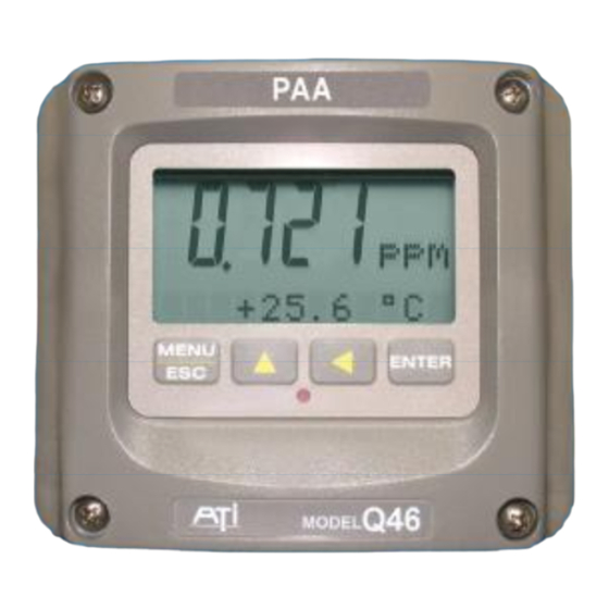
Part 1 - Introduction General The Model Q46/85 is an on-line monitoring system designed for the continuous measurement of Peracetic Acid (PAA) concentration in solution. The full scale operating range of the system may be selected by the user for 0-20.00 ppm, 0-200.0 ppm, or 0-2000 ppm, and the sensing system will operate on water streams with temperatures ranging from 0 to 50°C. -
Page 5: Standard System
Q46H/85 PAA System Part 2 – Analyzer Mounting Standard System The standard model Q46/85 system includes three main components, the Q46 analyzer, a constant head flow cell, and a PAA sensor. A low-volume flowcell is also available for applications where sample flowrate and pressure can be carefully controlled. Figure 1 shows a typical installation including the optional pH sensor. -
Page 6: Figure 2 - Monitorings
Q46H/85 PAA System Part 2 – Analyzer Mounting Figure 2 below shows the same standard flowcell assembly and PAA sensor along with the conventional type pH sensor. A special adapter is required to hold the pH sensor in its proper location in the flowcell inlet chamber. -
Page 7: Figure 3 - Sealed Flowcell
Q46H/85 PAA System Part 2 – Analyzer Mounting Figure 3 below shows an installation using a (00-1522) sealed flowcell for the PAA sensor and a (00- 1527) sealed flowcell for the pH sensor. This type of installation requires careful flow control. We recommend the use of our (03-0371) flow control assembly when using sealed flowcells. -
Page 8: Features
Q46H/85 PAA System Part 2 – Analyzer Mounting Features • Standard Q46H Analyzers have fully inputs and outputs. Analog outputs are additionally completely isolated from each other • Available in either 90-260 VAC or 12-24 VDC power supply systems. All features remain the same in both variations •... -
Page 9: Q46/85 System Specifications
Q46H/85 PAA System Part 2 – Analyzer Mounting Q46/85 System Specifications isplayed Parameters Main input, 0.01 ppm to 2000 ppm Sensor temperature, -10.0 to 55.0 °C (23 to 131 ºF) Sensor Current, 0.0–999.9 nA, 0.000 to 99.99 uA Loop current, 4.00 to 20.00 mA Sensor slope/offset Model number and software version PID Controller Status... -
Page 10: Q46H Performance Specifications
Q46H/85 PAA System Part 2 – Analyzer Mounting Power 90 - 260 VAC, 50-60 Hz, 10 VA max or 12-24 VDC, 500 mA max. Enclosure NEMA 4X (IP-66), polycarbonate, stainless steel hardware, weatherproof and corrosion resistant, Mounting Options Wall or pipe mount bracket standard. Bracket suitable for either 1.5”... -
Page 11: Part 2 - Analyzer Mounting
Q46H/85 PAA System Part 2 – Analyzer Mounting Part 2 – Analyzer Mounting General All Q46 Series instruments offer maximum mounting flexibility. A bracket is included with each unit that allows mounting to walls or pipes. In all cases, choose a location that is readily accessible for calibrations. -
Page 12: Wall Or Pipe Mount
Q46H/85 PAA System Part 2 – Analyzer Mounting Wall or Pipe Mount A PVC mounting bracket with attachment screws is supplied with each transmitter as shown in Figure 5. The multi-purpose bracket is attached to the rear of the enclosure using the four flat head screws. -
Page 13: Figure 6 - Wall Mounting
Q46H/85 PAA System Part 2 – Analyzer Mounting Figure 6 - Wall Mounting Diagram Figure 7 - Pipe Mounting Diagram O&M Manual Rev F (8/17) -
Page 14: Panel Mounting
Q46H/85 PAA System Part 2 – Analyzer Mounting Panel Mounting Panel mounting uses the panel mounting flange molded into the rear section of the enclosure. Figure 8 provides dimensions for the panel cutout required for mounting. The panel mounting bracket kit must be ordered separately (part number 05-0094). This kit contains a metal retainer bracket that attaches to the rear of the enclosure, 4 screws for attachment of this bracket, and a sealing gasket to insure that the panel mounted monitor provides a water tight seal when mounted to a panel. -
Page 15: Part 3 - Sensor/Flowcell Mounting
Part 3 – Sensor/Flowcell Mounting General Select a location within the maximum sensor cable length for mounting of the sensor flow cell. Constant-Head Flowcell PAA sensors are best used in a constant-head overflow chamber because variations in sample flow rate and pressure can cause unstable readings. When monitoring low concentrations (below 0.5 PPM), this method should always be used. -
Page 16: Sealed Flowcell
Q46H/85 PAA System Part 3 – Sensor/Flowcell Mounting 3.3 Sealed Flowcell Applications where the sample inlet flow is well controlled can use a simpler sealed flowcell. Using this flowcell requires that flow be controlled externally to about 400 cc/min. Variable flow rate or variable pressure will cause unstable readings in this flowcell. -
Page 17: Figure 11 - Sealed P H F
Q46H/85 PAA System Part 3 – Sensor/Flowcell Mounting Figure 11 - Sealed pH Flowcell Details O&M Manual Rev F (8/17) -
Page 18: Submersion Mounting
Q46H/85 PAA System Part 3 – Sensor/Flowcell Mounting Submersion Mounting Some applications are much easier done using the submersible sensor. This method can sometimes be used where flow is reasonably constant, and hydraulic head does not vary appreciably. PAA sensors can never be used in completely stagnant conditions. A flow velocity of at least 0.3 feet per second is normally required for measurement. -
Page 19: Part 4 - Electrical Installation
Part 4 – Electrical Installation General The Q46 is powered in one of two ways, depending on the version purchased. The 12-24 VDC powered analyzer requires a customer supplied DC power supply. The 90-260 VAC version requires line power. Please verify the type of unit before connecting any power. WARNING: Do not connect AC line power to a DC powered unit. -
Page 20: Figure 13 - Line Powerc
Q46H/85 PAA System Part 4 – Electrical Installation WARNING Disconnect line power voltage BEFORE connecting line power wires to Terminal TB7 of the power supply. The power supply accepts only standard three-wire single phase power. AC power supplies are configured for 90-260 VAC operation at the factory at time of order, and the power supply is labeled as such. -
Page 21: Figure 14 - Optional Relay
Q46H/85 PAA System Part 4 – Electrical Installation Relay Connection Three SPDT relays are provided on the power supply board. None of the relay contacts are powered. The user must supply the proper power to the contacts. For applications that require the same switched operating voltage as the Q46 (115 or 230 V), power may be jumpered from the power input terminals at TB7. -
Page 22: Figure 15 - Optional Relay
Q46H/85 PAA System Part 4 – Electrical Installation TB2, is used to connect to the optional 3-relay card (Figures 14) OR the optional third analog outputOut#3, Figure 15. The Q46 can be configured for only one of these optional features, and the hardware for either option must be factory installed. -
Page 23: Direct Sensor Connection
Q46H/85 PAA System Part 4 – Electrical Installation Direct Sensor Connection The sensor cable can be routed into the enclosure through one of cord-grips supplied with the unit. Routing sensor wiring through conduit is only recommended if a junction box is to be used. Some loose cable is needed near the installation point so that the sensor can be inserted and removed easily from the flowcell. -
Page 24: Sensor Wiring
Q46H/85 PAA System Part 4 – Electrical Installation Sensor Wiring The sensor cable can be quickly connected to the Q46 terminal strip by matching the wire colors on the cable to the color designations on the label in the monitor. A junction box is also available to provide a break point for long sensor cable runs. -
Page 25: Junction Box Connection
Q46H/85 PAA System Part 4 – Electrical Installation Junction Box Connection For installations where the sensor is to be located more than 25 feet from the monitor (max. 100 feet), a junction box must be used. The junction box is shown in Figure 19, and is supplied with a ½"... -
Page 26: Part 5 - Sensor Assembly
Part 5 – Sensor Assembly PAA Sensor Preparation The PAA sensor supplied with the Q46 is shipped dry. It will not operate until it is prepared by adding electrolyte and a membrane. Preparation of the sensor for operation must be done carefully. -
Page 27: Figure 21 - Submersible
Q46H/85 PAA System Part 5 – Sensor Assembly Submersible PAA sensors are made up of two separate parts, a submersion holder that also contains the temperature compensating element and a sensing module. The sensing module screws into the holder, with an o-ring providing a water tight connection. Follow the procedure below to prepare the PAA sensor for operation: Figure 21 - Submersible PAA Sensor Assembly 1. -
Page 28: Optional Ph Sensor
Q46H/85 PAA System Part 5 – Sensor Assembly The sensor is now ready for operation. The membrane should be stretched tightly across the tip of the sensor. CAUTION: When handling the assembled sensor, do not set the sensor on its tip or damage to the membrane will result. -
Page 29: Part 6 - Configuration
Part 6 – Configuration User Interface The user interface for the Q46 Series instrument consists of a custom display and a membrane keypad. All functions are accessed from this user interface (no internal jumpers, pots, etc.). RELAY 4-DIGIT INDICATOR MAIN DISPLAY MENU ICONS MENU ICONS SIGN... -
Page 30: Keys
Q46H/85 PAA System Part 6 – Configuration 6.11 Keys All user configurations occur through the use of four membrane keys. These keys are used as follows: MENU/ESC To scroll through the menu section headers or to escape from anywhere in software. The escape sequence allows the user to back out of any changes in a logical manner. - Page 31 Q46H/85 PAA System Part 6 – Configuration Lower Line During normal operation, the lower line of the display indicates user- selected secondary measurements that the system is making. This also includes calibration data from the last calibration sequence and the transmitter model number and software version.
-
Page 32: Software
Q46H/85 PAA System Part 6 – Configuration Relay Area A/B The relay area contains two icons that indicate the state of the system relays (if the relay card is installed). Relay C is normally configured for FAIL indication, so it is only displayed on the lower MEASURE display line. - Page 33 Q46H/85 PAA System Part 6 – Configuration Any data that may be changed will be flashing. This flashing indicates user entry mode and is initiated by pressing the ENTER key. The UP arrow key will increase a flashing digit from 0 to 9. The LEFT arrow key moves the flashing digit from right to left.
-
Page 34: Figure 23 - Software Map
Q46H/85 PAA System Part 6 – Configuration Start MENU ME NU ME NU ME NU ME NU ME NU MEASURE CONFIG CONTROL DIAG ES C ES C ES C ES C ES C SECTIONS (display only) E NT ER E NT ER E NT ER E NT ER Temperature... -
Page 35: Measure Menu [Measure]
Q46H/85 PAA System Part 6 – Configuration 6.22 Measure Menu [MEASURE] The default menu for the system is the display-only menu MEASURE. This menu is a display-only measurement menu, and has no changeable list items. When left alone, the instrument will automatically return to this menu after approximately 30 minutes. -
Page 36: Calibration Menu [Cal]
Q46H/85 PAA System Part 6 – Configuration 6.23 Calibration Menu [CAL] The calibration menu contains items for frequent calibration of user parameters. There are four items in this list: Cal PAA, Cal Temp, Set Range, and Cal Zero. Cal PAA The PAA calibration function allows the user to adjust the transmitter span reading to match a reference solution, or to set the sensor zero point. - Page 37 Q46H/85 PAA System Part 6 – Configuration Set Delay The delay function sets the amount of damping on the instrument. This function allows the user to apply a first order time delay function to the PAA measurements being made. Both the display and the output value are affected by the degree of damping.
- Page 38 Q46H/85 PAA System Part 6 – Configuration Iout#1 Mode This function sets analog output #1 to either track PAA (default) or enables the PID controller to operate on the PAA input. Press ENTER to initiate user entry mode, and the entire value will flash. Use the UP arrow key to modify the desired value;...
- Page 39 Q46H/85 PAA System Part 6 – Configuration The CON setting enables normal setpoint operation for Relay B. Relay B then operates identically to Relay A, with settings for setpoint, hysteresis, delay and phasing appearing in the CONFIG menu automatically. See Figure 19 for details.
-
Page 40: Figure 24 - Automatic P H B
Q46H/85 PAA System Part 6 – Configuration Table 1 Table 2 4.00 pH 7.00 pH 10.00 pH 4.00 pH 7.00 pH 9.18 pH ºC °C °C ºC °C °C 4.00 7.10 10.27 4.00 7.10 9.46 3.99 7.06 10.15 3.99 7.06 9.33 4.00 7.02... -
Page 41: Control Menu [Control]
Q46H/85 PAA System Part 6 – Configuration 6.25 Control Menu [CONTROL] The Control Menu contains all of the output control user settings Set 4 mA These functions set the main 4 and 20 mA current loop transmitter. The Set 20 mA units displayed depend on the selection made in the CONFIG menu for [Iout1=PAA] Iout #1 Mode. - Page 42 Q46H/85 PAA System Part 6 – Configuration controller (manual reset.) Increasing this value will make the controller more responsive. PID Deriv Derivative is a second order implementation of Integral, used to supress [Iout1=PID] “second-order” effects from process variables. These variables may include items like pumps or mixers that may have minor impacts on the measured value.
-
Page 43: Figure 25 - Control Relay
Q46H/85 PAA System Part 6 – Configuration *A Setpoint This function establishes the PAA trip point for relay A. The entry value is limited to a value within the range specified in “Set Range”. Use the LEFT arrow key to select the first digit to be modified. Then use the UP and LEFT arrow keys to select the desired numerical value. -
Page 44: Figure 26 - Alarm Relaye
Q46H/85 PAA System Part 6 – Configuration If Relay A Mode is set to Alarm Mode, AL, then the following settings will *Setpnt A-HI appear in the Config Menu list automatically. In this mode, two setpoints *Hyst A-HI can be selected on the same relay, to create an alarm band. Phase HI *Delay A-HI selection causes the relay to energize outside of the band, and Phase *Setpnt A-LO... -
Page 45: Diagnostics Menu [Diag]
Q46H/85 PAA System Part 6 – Configuration 6.26 Diagnostics Menu [DIAG] The diagnostics menu contains all of the user settings that are specific to the system diagnostic functions, as well as functions that aid in troubleshooting application problems. Set Hold The Set Hold function locks the current loop output values on the present process value and halts operation of the PID controller. - Page 46 Q46H/85 PAA System Part 6 – Configuration PID Timer This function sets a timer to monitor the amount of time the PID controller remains at 0% or 100%. This function only appears if the PID controller is enabled. If the timer is set to 0000, the feature is effectively disabled.
- Page 47 Q46H/85 PAA System Part 6 – Configuration Fail Val #2 This function sets the value of current loop output #2 under a FAIL condition. The settings and operation are identical to Fail Out for output *Fail Out #3 OPTIONAL. This function sets the fail-mode of current loop output #3 under a FAIL condition.
-
Page 48: Part 7 - Calibration
Part 7 – Calibration PAA Calibration Once power is applied, the sensor must be given time to stabilize. This is best done by following the zeroing procedure below. Establishing a stable zero is critical to the proper operation of the monitor. -
Page 49: Paa Span Cal
Q46H/85 PAA System Part 7 – Calibration value remain high and result in calibration failures, review the Service section of this manual, and then contact the service dept. at ATI for further assistance. The sensor zero offset value in nA from the last zero calibration is displayed on the lower line of the Default Menus for information purposes. -
Page 50: Temperature Calibration
Q46H/85 PAA System Part 7 – Calibration 8. The screen will display the last measured ppm value and a message will be displayed prompting the user for the lab value. The user must then modify the screen value with the arrow keys and press ENTER. -
Page 51: Ph Calibration
Q46H/85 PAA System Part 7 – Calibration pH Calibration The pH calibration menus will not be seen unless the optional pH sensor input is turned ON and a special pH sensor is connected to the input of the instrument. See Section 6.24 Configuration Menu [CONFIG] for more details. -
Page 52: One-Point Ph Cal
Q46H/85 PAA System Part 7 – Calibration 7.32 One-Point pH Cal For this calibration method, the sensor may be removed, cleaned, and placed into a known pH buffer, or, it may be calibrated on-line against a known reference value. If the sensor is removed, thoroughly clean the pH sensor and place it into the pH calibration buffer, stirring is several times before letting it rest in the beaker. -
Page 53: Part 8 - Pid Controller Details
Part 8 – PID Controller Details PID Description PID control, like many other control schemes, are used in chemical control to improve the efficiency of chemical addition or control. By properly tuning the control loop that controls chemical addition, only the amount of chemical that is truly required is added to the system, saving money. - Page 54 Q46H/85 PAA System Part 8 – PID Controller Details controller utilizes the same form of the algorithm shown above, it is likely similar settings can for made if the units on the settings are exactly the same. Be careful of this, as many times the units are the reciprocals of each other (i.e.
-
Page 55: Classical Pid Tuning
Q46H/85 PAA System Part 8 – PID Controller Details Classical PID Tuning Unlike many high speed position applications where PID loops are commonly used, the chemical feed application employed by this instrument does not require intense mathematical exercise to determine tuning parameters for the PID. In fact, the risk of instability is far greater with overly tuned PID control schemes. - Page 56 Q46H/85 PAA System Part 8 – PID Controller Details of operation, and become highly exponential at the extreme ranges of the measuring scale. In addition, if a chemical process is not symmetrical, that means it responds differentially to the addition and subtraction of chemical. It is important in these applications to study steady-state impact as well as step-change impact to process changes.
-
Page 57: Part 9 - System Maintenance
Part 9 – System Maintenance General The Q46/85 PAA System will generally provide unattended operation over long periods of time. With proper care, the system should continue to provide measurements indefinitely. For reliable operation, maintenance on the system must be done on a regular schedule. Keep in mind that preventive maintenance on a regular schedule is much less troublesome than emergency maintenance that always seems to come at the wrong time. -
Page 58: Sensor Acid Cleaning
Q46H/85 PAA System Part 9 – System Maintenance 9.31 Sensor Acid Cleaning Over an extended operating period, PAA sensors can slowly accumulate deposits on the surface of the gold electrode. Typically, this type of buildup occurs over years of operation, but can sometimes occur more quickly in high levels of manganese, iron, or other metals are dissolved in the water. -
Page 59: Part 10 - Troubleshooting
Part 10 – Troubleshooting 10.1 General The information included in this section is intended to be used in an attempt to quickly resolve an operational problem with the system. During any troubleshooting process, it will save the most time if the operator can first determine if the problem is related to the analyzer, sensor, or some external source. -
Page 60: Analyzer Tests
Q46H/85 PAA System Part 10 – Troubleshooting loads when they are switched on an off, the relay wiring placement can result in electrical interference for other devices. This can be quickly resolved by moving wiring, or by adding very inexpensive snubbers (such As Quencharcs) to the load. 8. - Page 61 Q46H/85 PAA System Part 10 – Troubleshooting MESSAGE DESCRIPTION POSSIBLE CORRECTION ≤ Max is 200 Entry failed, maximum user value allowed is 200. Reduce value to ≥ Min is 200 Entry failed, minimum value allowed is 200. Increase value to Cal Unstable Calibration problem, data...
-
Page 62: Figure 29 - Display Messages
Q46H/85 PAA System Part 10 – Troubleshooting MESSAGE DESCRIPTION POSSIBLE CORRECTION PAA Cal Fail Failure of PAA calibration. FAIL icon will Clean sensor redo zero and span calibration. not extinguish until successful calibration If still failure, sensor slope may be less than has been performed, or 30 minutes passes 25% or greater than 250%. -
Page 63: Sensor Tests
Q46H/85 PAA System Part 10 – Troubleshooting 10.5 Sensor Tests 1. Check the membrane condition. A membrane that is not stretched smoothly across the tip of the sensor will cause unstable measurements. If necessary, change membrane and electrolyte. 2. Residual PAA sensors can be tested with a digital voltmeter (DVM) to determine if a major sensor problem exists. - Page 64 Q46H/85 PAA System Part 10 – Troubleshooting should dry out sufficiently to allow normal sensor operation. However, steps 2c thru 2e above will have to be repeated after drying to see if the problem is gone. 3. Acid clean the sensor electrodes in accordance with the procedure on the previous page. O&M Manual Rev F (8/17)
-
Page 65: Spare Parts
Spare Parts Electronics 03-0385-6 Q46/85 Front lid assembly 07-0310 Q46/85 Monitor, 100-240 VAC 07-0311 Q46/85 Monitor, 12-24 VDC 07-0314 Q46/85 Monitor, 100-240 VAC, w/Profibus 07-0315 Q46/85 Monitor, 12-24 VDC, w/Profibus 23-0029 Fuse, T-Lag, 630mA, 250V, TR-5 (for AC and DC Analyzers) 38-0072 Terminal block plug, 3 position (relays) 38-0073... - Page 66 PRODUCT WARRANTY Analytical Technology, Inc. (Manufacturer) warrants to the Customer that if any part(s) of the Manufacturer's products proves to be defective in materials or workmanship within the earlier of 18 months of the date of shipment or 12 months of the date of start-up, such defective parts will be repaired or replaced free of charge.
- Page 67 WATER QUALITY MONITORS GAS DETECTION PRODUCTS Dissolved Oxygen Ammonia Carbon Monoxide Free Chlorine Hydrogen Combined Chlorine Nitric Oxide Total Chlorine Oxygen Residual Chlorine Dioxide Cl2 Phosgene Potassium Permanganate Bromine Chlorine Dissolved Ozone Chlorine Dioxide pH/ORP Fluorine Conductivity Iodine Hydrogen Peroxide Acid Gases Peracetic Acid O Ethylene Oxide...
Need help?
Do you have a question about the Q46-85 and is the answer not in the manual?
Questions and answers