Table of Contents
Advertisement
Quick Links
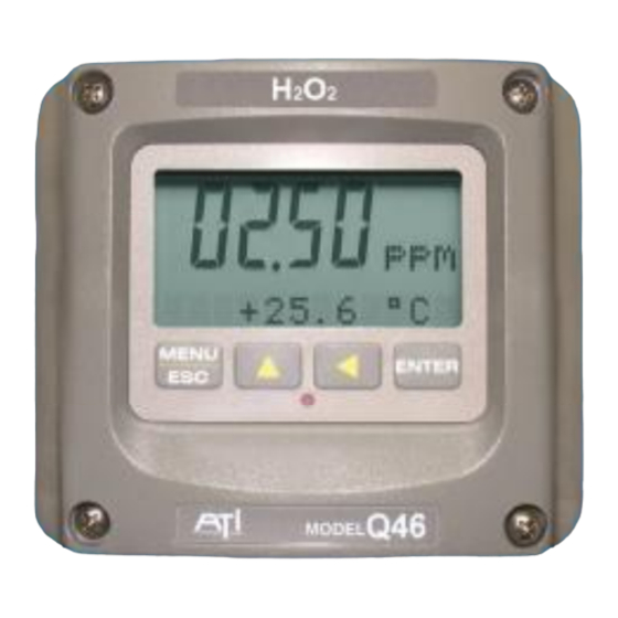
Hydrogen Peroxide Monitor
Home Office
Analytical Technology, Inc.
6 Iron Bridge Drive
Collegeville, PA 19426
Phone: 800-959-0299
610-917-0991
Fax:
610-917-0992
Email: sales@analyticaltechnology.com
O & M Manual
Model Q46/84
European Office
ATI (UK) Limited
Unit 1 & 2 Gatehead Business Park
Delph New Road, Delph
Saddleworth OL3 5DE
Phone: +44 (0)1457-873-318
Fax:
+ 44 (0)1457-874-468
Email: sales@atiuk.com
Advertisement
Table of Contents

Related Manuals for ATI Technologies Q46/84


Summary of Contents for ATI Technologies Q46/84
- Page 1 O & M Manual Model Q46/84 Hydrogen Peroxide Monitor Home Office European Office Analytical Technology, Inc. ATI (UK) Limited 6 Iron Bridge Drive Unit 1 & 2 Gatehead Business Park Collegeville, PA 19426 Delph New Road, Delph Phone: 800-959-0299 Saddleworth OL3 5DE...
-
Page 2: Table Of Contents
Standard System ........5 8.4 Manual PID Override Control .......45 Features ............. 6 Common PID Pitfalls .......45 Q46/84 System Specifications ....7 PART 9 – SYSTEM MAINTENANCE ....47 Q46 Performance Specifications ....8 General .............47 PART 2 – ANALYZER MOUNTING ....9 Analyzer Maintenance ......47... -
Page 3: Table Of Figures
Table of Figures 1 - T ....................... 5 IGURE YPICAL ONITORING YSTEM 2 - Q46 E ....................... 9 IGURE NCLOSURE IMENSIONS 3 - W ....................10 IGURE ALL OR OUNT RACKET 4 - W ......................11 IGURE OUNTING IAGRAM 5 - P ...................... -
Page 4: Part 1 - Introduction
0-2.000 ppm, 0-20.00 ppm, or 0-200.0 ppm, and the sensing system will operate on water streams with temperatures ranging from 0 to 50°C. The Q46/84 Monitor is engineered for applications in which H is applied to water for sterilization purposes. -
Page 5: Standard System
Q46/84 Hydrogen Peroxide Monitor Part 1 – Introduction Standard System The standard model Q46H/84 system includes three main components, the Q46/84 analyzer, a constant head flow cell, and an H sensor. A sealed flowcell is also available for applications where sample flowrate and pressure can be carefully controlled. -
Page 6: Features
Q46/84 Hydrogen Peroxide Monitor Part 1 – Introduction Features • Standard Q46H analyzers have fully isolated inputs and outputs. Analog outputs are additionally completely isolated from each other. • Available in either 90-260VAC or 12-24 VDC power supply systems. All features remain the same in both variations. -
Page 7: Q46/84 System Specifications
Q46/84 Hydrogen Peroxide Monitor Part 1 – Introduction Q46/84 System Specifications Displayed Parameters Main input, 0.001 ppm to 200.0 ppm Sensor temperature, -10.0 to 55.0 °C (23 to 131 ºF) Sensor Current, 0.0–999.9 nA, 0.000 to 99.99 uA Loop current, 4.00 to 20.00 mA... -
Page 8: Q46 Performance Specifications
Q46/84 Hydrogen Peroxide Monitor Part 1 – Introduction Power 90 - 260 VAC, 50-60 Hz, 10 VA max or 12-24 VDC, 500 mA max. Enclosure NEMA 4X, polycarbonate, stainless steel hardware, weatherproof and corrosion resistant, Mounting Options Wall or pipe mount bracket standard. Bracket suitable for either 1.5”... -
Page 9: Part 2 - Analyzer Mounting
Part 2 – Analyzer Mounting General All Q46 Series instruments offer maximum mounting flexibility. A bracket is included with each unit that allows mounting to walls or pipes. In all cases, choose a location that is readily accessible for calibrations. Also consider that it may be necessary to utilize a location where solutions can be used during the calibration process. -
Page 10: Wall Or Pipe Mount
Q46/84 Hydrogen Peroxide Monitor Part 2– Analyzer Mounting Wall or Pipe Mount A PVC mounting bracket with attachment screws is supplied with each transmitter (see Figure 3 below for dimensions). The multi-purpose bracket is attached to the rear of the enclosure using the four flat head screws. -
Page 11: Figure 4 - Wall Mounting Diagram
Q46/84 Hydrogen Peroxide Monitor Part 2– Analyzer Mounting Figure 4 - Wall Mounting Diagram Figure 5 - Pipe Mounting Diagram O&M Manual Rev-H (6/17) -
Page 12: Panel Mounting
Q46/84 Hydrogen Peroxide Monitor Part 2– Analyzer Mounting Panel Mounting Panel mounting of an AC powered monitor uses the panel mounting flange molded into the rear section of the enclosure. Figure 6 provides dimensions for the panel cutout required for mounting. -
Page 13: Part 3 - Sensor/Flowcell Mounting
Part 3 – Sensor/Flowcell Mounting General Select a location within the maximum sensor cable length for mounting of the sensor flow cell. Constant-Head Flowcell sensors are best used in a constant-head overflow chamber because variations in sample flow rate and pressure can cause unstable readings. When monitoring low concentrations (below 0.5 PPM), this method should always be used. -
Page 14: Sealed Flowcell
Q46/84 Hydrogen Peroxide Monitor Part 3 – Sensor/Flowcell Mounting Once mounted, inlet and drain connections must be made. The flow cell contains a 1/8" MNPT inlet connection and a 3/8" MNPT drain connection. Hose barbs for the inlet and drain connections are supplied with the flow cell for use with flexible tubing. -
Page 15: Part 4 - Electrical Installation
Part 4 – Electrical Installation General The Q46 is powered in one of two ways, depending on the version purchased. The 12-24 VDC powered analyzer requires a customer supplied DC power supply. The 90-260 VAC version requires line power. Please verify the type of unit before connecting any power. WARNING Do not connect AC line power to the DC version. -
Page 16: Figure 9 - Line Power Connection
Q46/84 Hydrogen Peroxide Monitor Part 4 – Electrical Installation Connect HOT, NEUTRAL, and GROUND to the matching designations on terminal strip TB7. WARNING Disconnect line power voltage BEFORE connecting line power wires to Terminal TB7 of the power supply. The power supply accepts only standard three-wire single phase power. -
Page 17: Figure 10 - Relay Contacts
Q46/84 Hydrogen Peroxide Monitor Part 4 – Electrical Installation Relay Connection Three SPDT relays are provided on the power supply board. None of the relay contacts are powered. The user must supply the proper power to the contacts. For applications that require the same switched operating voltage as the Q46 (115 or 230 V), power may be jumpered from the power input terminals at TB7. -
Page 18: Figure 11 - Optional Relay Board Wiring
Q46/84 Hydrogen Peroxide Monitor Part 4 – Electrical Installation TB2, is used to connect to the optional 3-relay card (Figures 11) OR the optional third analog output, Out#3, (Figure 12). The Q46 can be configured for only one of these optional features, and the hardware for either option must be factory installed. -
Page 19: Direct Sensor Connection
Q46/84 Hydrogen Peroxide Monitor Part 4 – Electrical Installation Direct Sensor Connection The sensor cable can be routed into the enclosure through one of cord-grips supplied with the unit. Routing sensor wiring through conduit is only recommended if a junction box is to be used. -
Page 20: Figure 14 - Sensor Wiring
Q46/84 Hydrogen Peroxide Monitor Part 4 – Electrical Installation Sensor Wiring The sensor cable can be quickly connected to the Q46 terminal strip by matching the wire colors on the cable to the color designations on the label in the monitor. A junction box is also available to provide a break point for long sensor cable runs. -
Page 21: Junction Box Connection
Q46/84 Hydrogen Peroxide Monitor Part 4 – Electrical Installation Junction Box Connection For installations where the sensor is to be located more than 25 feet from the monitor (max. 100 feet), a junction box must be used. The junction box is shown in Figure 15, and is supplied with a ½"... -
Page 22: Part 5 - Sensor Assembly
Part 5 – Sensor Assembly Sensor Preparation The hydrogen peroxide sensor supplied with the Q46/84 is shipped dry. It will not operate until it is prepared by adding electrolyte and a membrane. Preparation of the sensor for operation must be done carefully. The procedure should be done by a qualified technician, and it should only be done when the system is ready for operation. - Page 23 Q46/84 Hydrogen Peroxide Monitor Part 5 – Sensor Assembly 3. From the package of membranes supplied with the sensor, place a new membrane into the front nut. The membrane is white in color and is separated from other membranes by a light blue paper spacer.
-
Page 24: Part 6 - Configuration
Part 6 – Configuration User Interface The user interface for the Q46 Series instrument consists of a custom display and a membrane keypad. All functions are accessed from this user interface (no internal jumpers, pots, etc.). RELAY 4-DIGIT INDICATOR MAIN DISPLAY MENU ICONS MENU ICONS SIGN... -
Page 25: Keys
Q46/84 Hydrogen Peroxide Monitor Part 6 – Configuration 6.11 Keys All user configuration occurs through the use of four membrane keys. These keys are used as follows: MENU/ESC To scroll through the menu section headers or to escape from anywhere in software. -
Page 26: Software
Q46/84 Hydrogen Peroxide Monitor Part 6 – Configuration Icon Area The icon area contains display icons that assist the user in set-up and indicate important states of system functions. The CAL, CONFIG, and DIAG icons are used to tell the user what branch of the software tree the user is in while scrolling through the menu items. -
Page 27: Software Navigation
Q46/84 Hydrogen Peroxide Monitor Part 6 – Configuration 6.21 Software Navigation Within the CAL, CONFIG, CONTROL, and DIAG menu sections is a list of selectable items. Once a menu section (such as CONFIG) has been selected with the MENU key, the user can access the item list in this section by pressing either the ENTER key or the UP arrow key. -
Page 28: Figure 18 - Software Map
Q46/84 Hydrogen Peroxide Monitor Part 6 – Configuration Start MENU MENU ME NU MENU ME NU MENU MEASURE CONFIG CONTROL DIAG E S C E SC E SC ES C E SC SECTIONS (display only) E NTE R E NTE R... -
Page 29: Measure Menu [Measure]
Q46/84 Hydrogen Peroxide Monitor Part 6 – Configuration 6.22 Measure Menu [MEASURE] The default menu for the system is the display-only menu MEASURE. This menu is a display-only measurement menu, and has no changeable list items. When left alone, the instrument will automatically return to this menu after approximately 30 minutes. -
Page 30: Calibration Menu [Cal]
Q46/84 Hydrogen Peroxide Monitor Part 6 – Configuration 6.23 Calibration Menu [CAL] The calibration menu contains items for frequent calibration of user parameters. There are four items in this list: Cal H , Cal Temp, Set Range, and Cal Zero. - Page 31 Q46/84 Hydrogen Peroxide Monitor Part 6 – Configuration The STN display provides the highest possible contrast and widest viewing angle under all conditions. Contrast control of this type of display is generally not necessary, so contrast control is provided as a means for possible adjustment due to aging at extreme ranges.
- Page 32 Q46/84 Hydrogen Peroxide Monitor Part 6 – Configuration *Iout#3 Mode OPTIONAL. This function sets analog output #3 for temperature (default) or peroxide. Press ENTER to initiate user entry mode, and the entire value will flash. Use the UP arrow key to modify the desired value;...
-
Page 33: Control Menu [Control]
Q46/84 Hydrogen Peroxide Monitor Part 6 – Configuration 6.25 Control Menu [CONTROL] The Control Menu contains all of the output control user settings: Set PID 0% If the PID is enabled, this function sets the minimum and maximum Set PID 100% controller end points. - Page 34 Q46/84 Hydrogen Peroxide Monitor Part 6 – Configuration value stored for the 20 mA point. The entry values are limited to values within the range specified in “Set Range”, and the 4 mA and the 20 mA point must be separated by at least 1% of this range Use the LEFT arrow key to select the first digit to be modified.
-
Page 35: Figure 19 - Control Relay Example
Q46/84 Hydrogen Peroxide Monitor Part 6 – Configuration *A Delay This function places an additional amount of time delay on the trip point for relay A. This delay is in addition to the main delay setting for the controller. The entry value is limited to a value between 0 and 999 seconds. -
Page 36: Figure 20 - Alarm Relay Example
Q46/84 Hydrogen Peroxide Monitor Part 6 – Configuration If Relay A Mode is set to Alarm Mode, AL, then the following settings will *Setpnt A-HI appear in the Config Menu list automatically. In this mode, two setpoints *Hyst A-HI can be selected on the same relay, to create an alarm band. Phase HI... -
Page 37: Diagnostics Menu [Diag]
Q46/84 Hydrogen Peroxide Monitor Part 6 – Configuration 6.26 Diagnostics Menu [DIAG] The diagnostics menu contains all of the user settings that are specific to the system diagnostic functions, as well as functions that aid in troubleshooting application problems. Set Hold The Set Hold function locks the current loop output values on the present process value, and halts operation of the PID controller. - Page 38 Q46/84 Hydrogen Peroxide Monitor Part 6 – Configuration PID Timer This function sets a timer to monitor the amount of time the PID controller remains at 0% or 100%. This function only appears if the PID controller is enabled. If the timer is set to 0000, the feature is effectively disabled.
- Page 39 Q46/84 Hydrogen Peroxide Monitor Part 6 – Configuration Fail Val #2 This function sets the value of current loop output #2 under a FAIL condition. The settings and operation are identical to Fail Out for output *Fail Out #3 OPTIONAL. This function sets the fail-mode of current loop output #3.
-
Page 40: Part 7 - Calibration
Part 7 – Calibration Hydrogen Peroxide Calibration Once power is applied, the sensor must be given time to stabilize. This is best done by following the zeroing procedure below. Establishing a stable zero is critical to the proper operation of the monitor. -
Page 41: H 2 O 2 Span Cal
Q46/84 Hydrogen Peroxide Monitor Part 7 – Calibration value remain high and result in calibration failures, review the Service section of this manual, and then contact the service dept. at ATI for further assistance. The sensor zero offset value in nA from the last zero calibration is displayed on the lower line of the Default Menus for information purposes. -
Page 42: Temperature Calibration
Q46/84 Hydrogen Peroxide Monitor Part 7 – Calibration 8. The screen will display the last measured ppm value and a message will be displayed prompting the user for the lab value. The user must then modify the screen value with the arrow keys and press ENTER. -
Page 43: Part 8 - Pid Controller Details
Part 8 – PID Controller Details PID Description PID control, like many other control schemes, are used in chemical control to improve the efficiency of chemical addition or control. By properly tuning the control loop that controls chemical addition, only the amount of chemical that is truly required is added to the system, saving money. - Page 44 Q46/84 Hydrogen Peroxide Monitor Part 8 – PID Controller Details made if the units on the settings are exactly the same. Be careful of this, as many times the units are the reciprocals of each other (ie. reps-per-min, sec-per-rep.) PID stands for “proportional, integral, derivative.” These terms describe the three elements of the complete controller action, and each contributes a specific reaction in the control process.
-
Page 45: Classical Pid Tuning
Q46/84 Hydrogen Peroxide Monitor Part 8 – PID Controller Details Classical PID Tuning Unlike many high speed position applications where PID loops are commonly used, the chemical feed application employed by this instrument does not require intense mathematical exercise to determine tuning parameters for the PID. - Page 46 Q46/84 Hydrogen Peroxide Monitor Part 8 – PID Controller Details The easiest process’ to control with closed-loop schemes are generally linear, and symmetrical, in nature. For example, controlling level in tank where the opening of valve for a fixed period of time corresponds linearly to the amount that flows into a tank.
-
Page 47: Part 9 - System Maintenance
Part 9 – System Maintenance General The Q46/84 Hydrogen Peroxide System will generally provide unattended operation over long periods of time. With proper care, the system should continue to provide measurements indefinitely. For reliable operation, maintenance on the system must be done on a regular schedule. -
Page 48: Sensor Acid Cleaning
Q46/84 Hydrogen Peroxide Monitor Part 9 – System Maintenance 9.31 Sensor Acid Cleaning Over an extended operating period, H sensors can slowly accumulate deposits on the surface of the platinum electrode. Typically, this type of buildup occurs over years of operation, but can sometimes occur more quickly in high levels of manganese, iron, or other metals are dissolved in the water. -
Page 49: Part 10 - Troubleshooting
Part 10 – Troubleshooting 10.1 General The information included in this section is intended to be used in an attempt to quickly resolve an operational problem with the system. During any troubleshooting process, it will save the most time if the operator can first determine if the problem is related to the analyzer, sensor, or some external source. -
Page 50: Analyzer Tests
Q46/84 Hydrogen Peroxide Monitor Part 10 - Troubleshooting lower level. Also, due to the large amount of energy present in circuits driving these types of loads when they are switched on an off, the relay wiring placement can result in electrical interference for other devices. -
Page 51: Figure 22 - Display Messages
Q46/84 Hydrogen Peroxide Monitor Part 10 - Troubleshooting Unlocked! Transmitter security has just been unlocked. Displayed just after security code has been entered. Offset High The sensor zero offset point is out of the Check wiring connections to sensor. Allow acceptable range of –100 to +100 nA. -
Page 52: Sensor Tests
Q46/84 Hydrogen Peroxide Monitor Part 10 - Troubleshooting 10.5 Sensor Tests 1. Check the membrane condition. A membrane that is not stretched smoothly across the tip of the sensor will cause unstable measurements. If necessary, change membrane and electrolyte. 2. Residual H sensors can be tested with a digital voltmeter (DVM) to determine if a major sensor problem exists. -
Page 53: Spare Parts
Q46/84 Front lid assembly 07-0398 Q46/84 Monitor, 100-240 VAC 07-0399 Q46/84 Monitor, 12-24 VDC 07-0400 Q46/84 Monitor, 100-240 VAC, w/Profibus 07-0401 Q46/84 Monitor, 12-24 VDC, w/Profibus 23-0029 Fuse, T-Lag, 630mA, 250V, TR-5 (for AC or DC Analyzers) 38-0072 Terminal block plug, 3 position (relays) - Page 54 PRODUCT WARRANTY Analytical Technology, Inc. (Manufacturer) warrants to the Customer that if any part(s) of the Manufacturer's products proves to be defective in materials or workmanship within the earlier of 18 months of the date of shipment or 12 months of the date of start-up, such defective parts will be repaired or replaced free of charge.
- Page 55 WATER QUALITY MONITORS GAS DETECTION PRODUCTS Dissolved Oxygen Ammonia Carbon Monoxide Free Chlorine Hydrogen Combined Chlorine Nitric Oxide Total Chlorine Oxygen Residual Chlorine Dioxide Cl2 Phosgene Potassium Permanganate Bromine Chlorine Dissolved Ozone Chlorine Dioxide pH/ORP Fluorine Conductivity Iodine Hydrogen Peroxide Acid Gases Peracetic Acid O Ethylene Oxide...
Need help?
Do you have a question about the Q46/84 and is the answer not in the manual?
Questions and answers