
Subscribe to Our Youtube Channel
Related Manuals for STI Magnetrol Kotron 811


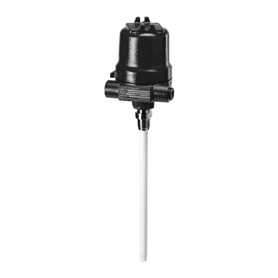
Summary of Contents for STI Magnetrol Kotron 811
- Page 1 Kotron ® Model 811 RF Point Level Sensor Installation and Operating Manual Capacitance Level Measurement...
-
Page 2: Kotron Model
Notes do not normally contain actions. They follow the procedural steps to which Warranty they refer. All Magnetrol/STI electronic level and flow controls are Cautions warranted free of defects in materials or workmanship for Cautions alert the technician to special conditions that... -
Page 3: Table Of Contents
Kotron Model 811 RF Point Level Sensor Table of Contents 1.0 Complete Installation 1.8.3 Low Level Alarm Fail-safe Low – with media on the probe ........12 1.1 Unpacking ..............1 1.8.4 High Level Alarm Fail-safe High – with 1.2 Electrostatic Discharge (ESD) Handling Procedure ..1 no media on the probe ........12 1.3 Before You Begin ............2 1.8.5 High Level Alarm Fail-safe High –... -
Page 4: Complete Installation
Complete Installation This section provides detailed procedures for properly installing, configuring, and, as needed, troubleshooting the Kotron Model 811 RF Point Level Sensor. Unpacking Unpack the instrument carefully. Make sure all compo- nents have been removed from the packing material. Check all the contents against the packing slip and report any discrepancies to the factory. -
Page 5: Before You Begin
Before You Begin 1.3.1 Site Preparation Each Kotron Model 811 sensor is built to match the specific physical specifications of the required installation. Make sure the probe connection is correct for the threaded or flanged mounting on the vessel or tank where the trans- mitter will be placed. -
Page 6: Mounting
Mounting The Model 811 sensor can be mounted to a tank using a variety of process connections. Make sure all mounting connections are properly in place on the tank before installing the probe. Make sure the Kotron probe is correct for the intended installation. It is common practice to use the metal tank wall as the reference electrode. -
Page 7: Horizontal Mounting
1.4.1 Horizontal Mounting Alarm (narrow differential) applications only Horizontally mounted probes provide a high degree of sen- sitivity for use with non-conductive liquids as only approx- imately 0.5 inches (12 mm) of level change is required to completely cover (or uncover) the probe. Figure 1 Horizontally mounted probes should be installed so that Recommended Horizontal Mounting... -
Page 8: Probe Installation
Probe Installation 1.5.1 Installing a Guarded Probe 1. Thread electronics/probe assembly (pre-assembled) into mounting bushing on tank. 2. Tighten securely (ensure that the wrench is applied only to the mounting gland). Refer to Figure 8. 3. Proceed to Wiring, Section 1.7, on page 8. 1.5.2 Installing a Standard Probe Figure 7 Before installing, ensure the:... -
Page 9: Installing A Remote Mount Unit
3. Apply thread sealant to the mounting nut. Screw the mounting nut into the mounting connection until tight. 4. Remove the Mylar housing insulator located over the clamp. DO NOT DISCARD. Probe OPEN (White) 5. Loosen both socket head screws from the clamp. Pull the clamp and Teflon retaining bushing off of the probe. -
Page 10: Probe Housing Connections
1.6.1.2 Probe Housing Connections 1. Screw probe housing onto the probe. PROBE WIRE CONNECTIONS 2. Attach the red guard wire to the slip-on guard connection on probe. Refer to Figure 10a, Probe Wire Connections. 3. Attach the white probe wire to the probe screw on top of the probe. -
Page 11: Wiring
Wiring 1.7.1 Probe Wiring All power and control connections are made at the terminal strip within the amplifier enclosure, EXCEPT GROUND- ING. Power grounding must be made at green ground screw on the housing base. 16AWG is recommended for power and control circuits. NOTE: There are special wiring exceptions for intrinsic safety. -
Page 12: Electrical Wiring
1.7.2 Electrical Wiring 1. Connect power leads to applicable AC or DC terminals as marked. Refer to Figure 13. 2. a. Connect control circuit leads to relay terminals Refer to Figure 13. Make sure the load to be controlled is with- in the relay’s rated capacity. -
Page 13: Relay Wiring Chart
1.7.4 RELAY WIRING CHART Relay Terminals Kotron Material Fail-safe Relay Power Level Coil COM to NC COM to NO HLFS De-energized Closed Open High LLFS Energized Open Closed HLFS Energized Open Closed LLFS De-energized Closed Open HLFS De-energized Closed Open High LLFS De-energized... -
Page 14: Low Level Alarm Fail-Safe Low - With No Media On The Probe
4.2 Potentiometers a. Time Delay • Allows continuous adjustment of time delay within limits of DIP switch range chosen • Clockwise rotation increases delay. b. Differential • Allows continuous adjustment of pump or valve control ON to OFF. • Clockwise rotation increases differential. Full coun- terclockwise rotation is the narrowest differential and is used for alarm applications. -
Page 15: Low Level Alarm Fail-Safe Low - With Media On The Probe
1.8.3 Low Level Alarm Fail-safe Low – with media on the probe: 1. Set DIP switch positions 1 OFF, 2 OFF, 3 ON and position 4 OFF. LED will be ON. 2. Turn the COARSE control clockwise until the LED turns OFF. -
Page 16: Calibration-Wide Differential
1.9 Calibration—Wide Differential 1.9.1 Set Point Adjustment Control 1. Turn on power to the instrument. 2. Remove housing cover. 3. Adjustments 3.1 Dip switch a. Fail-safe ON = high level OFF = low level b. Time Delay Direction ON = delay on rising level OFF = delay on falling level c. - Page 17 • This is an extremely fine adjustment. Sometimes it is necessary to go 1 to 2 turns past the final SETPOINT to stop relay chatter. A small amount of time delay (2 turns) can also be used. 4. The LED shows the status of the relay coil. LED on = relay energized.
-
Page 18: Time Delay
11. Differential control a. Low Level Fail-safe Slowly turn Differential control counterclockwise until the LED turns ON. The wide differential point is calibrated. b. High Level Fail-safe Slowly turn Differential control counterclockwise until the LED turns OFF. The wide differential point is calibrated. -
Page 19: Reference Information
Reference Information This section presents an overview of the operation of the Kotron Model 811 RF Point Level Sensor, information on troubleshooting common problems, intrinsic safety information, physical, functional and performance specifications, listings of agency approvals, and a list of recommended parts Description The Kotron Model 811 RF Point Level Sensor can be utilized in liquid or bulk material applications. -
Page 20: Switch Chatter
3. Measure the resistance between the probe and ground using the highest resistance scale available. If the resistance measures 10 Megohm to infinity and is stable, the probe is operating correctly. If the resistance measures less than 10 Megohm and/or is unstable, there may be a problem with the probe. -
Page 21: Agency Approvals
2.4 Agency Approvals Agency Approved Model Protection Method Area Classification 811-1X05-E0X Explosion Proof Explosion proof with intrinsically safe probe circuit 811-1X06-E0X Class I, Div. 1, Groups C & D with probe models: Class II, Div. 1, Groups E, F, & G 041-5XXX-XXX and NEMA 4X 8XX-XXX-XXX... -
Page 22: Agency Specifications - Intrinsically Safe Installation
2.4.1 Agency Specifications – Intrinsically Safe Installation 2.4.2 Agency Specifications – Explosion Proof Installation 50-608 Kotron Model 811 RF Point Level Sensor... -
Page 23: Parts
Parts 2.5.1 Replacement Parts Item Description Part Number Complete electronic assembly: Z30-9102-001 120 VAC Items 1 and 2 (listed below) Z30-9102-002 240 VAC Mounting bracket Z30-9102-003 24 VDC Z30-9102-004 12 VDC Z30-4502-001 120 VAC Z30-4502-002 240 VAC* Power supply board* (integral or remote) Z30-4502-003 12 VDC Z30-4502-004... -
Page 24: Specifications
Specifications 2.6.1 Functional Supply Voltage 120 VAC 50–60 Hz (+10%, -15%) 240 VAC 50–60 Hz (+10%, -15%) 24 VDC (±10%) 12 VDC (±10%) Power Consumption 120 or 240 VAC Less than 5 volt-amps 12 or 24 VDC 1 watt maximum Zero Range 0 pF minimum to 1000 pF maximum Adjustable Differential... -
Page 25: Physical
2.6.2 Physical Rotation Clearance: Rotation Clearance: Rotation Clearance: 2.63 (66) 3.00 (76) 2.63 (66) ➀ NEMA 4X/7/9 3/4" NPT 3/4" NPT Conduit 7.75 (197) Conduit ➀ Connection 6.86 NEMA 4X/7/9 Connection (174) 3/4" NPT 9.33 (247) (Plugged) Conduit 4.11 Connection 3/4"... -
Page 26: Model Numbers
3.0 Model Numbers BASIC MODEL — FM & CSA APPROVED MODELS Kotron RF Capacitance Level Switch INPUT POWER 120 VAC 240 VAC 24 VDC 12 VDC MOUNTING Integral Remote HOUSING NEMA 4X/7/9 Groups C & D, aluminum, ⁄ " NPT dual conduit NEMA 4X/7/9 Groups C &... -
Page 27: Notes
NOTES: 50-608 Kotron Model 811 RF Point Level Sensor... - Page 28 Prepaid transportation. through Magnetrol’s local representative or by contacting Magnetrol/STI will repair or replace the control at no cost the factory. Please supply the following information: to the purchaser (or owner) other than transportation if: 1. Company Name 1. Returned within the warranty period; and 2.
Need help?
Do you have a question about the Magnetrol Kotron 811 and is the answer not in the manual?
Questions and answers