
Related Manuals for SoluM SLG-DM101


Summary of Contents for SoluM SLG-DM101
- Page 1 Solu-M USB Gateway User Manual (SLG-DM101) PMN : USB Gateway FVIN : 6.0.24.4 Document Summary Author: D&C Development 1Group, D&C Division Distributor: Solum Co., Ltd.
- Page 2 The content of this document is subject to change without prior notice. The content of this document is intellectual property of Solum Co., Ltd. This document may not be reproduced or published without prior consent from Solum Co., Ltd. No part may be reproduced except as authorized by written permission.
- Page 3 Revision History Rev. Date Remark 10.29.2018 First Edition.
-
Page 4: Table Of Contents
Contents 1. Precautions ..........................5 2. Overview ........................... 6 3. Product Specifications ...................... 7 3.1 General Specifications ..............7 3.1.1 USB Gateway 3.2 RF Specifications ................8 3.2.1 USB Gateway 4. Product Description ......................9 4.1 Exteior ....................9 4.1.1 USB Gateway 5. -
Page 5: Precautions
1. Precautions “This RF device operates on the 2.4GHz frequency band and can produce radio interference. The device, therefore, may not be used for applications where safety of human lives is concerned.” 1) Usage Environment Take extra caution when using this RF device in the vicinity of other electronic devices and appliances. -
Page 6: Overview
2. Overview USB Gateway make up a system the electronically displays price and other product information that are traditionally shown printed or written on paper in places like the supermarket. Here, ESL(Electronic Shelf Label) USB Gateway receives product price updates from the server and uploads the new data to the applicable electronic shelf label tags (ESL-Tag), changing the displayed price information. -
Page 7: Product Specifications
3. Product Specifications 3.1 General Specifications 3.1.1. USB Gateway General USB2.0 Communication Zigbee RF(based on IEEE 802.15.4) Dimension (W*H*D) 30 * 200 * 11 (mm) Weight (g) Enclosure Plastic (ABS) Power USB Power (5V,0.5A) -
Page 8: Rf Specifications
3. 2 RF Specifications 3.2.1 Gateway Category Specification Note Antenna Type Dipole Antenna (external type) Transmit Frequency 2405MHz ~ 2480MHz Receive Frequency 2405MHz ~ 2480MHz Antenna gain 2 dBi Modulation O-QPSK Channels 16ch Operating 0℃ to +40℃ Temperature Power USB Power (5V, 500mA) -
Page 9: Usb Gateway
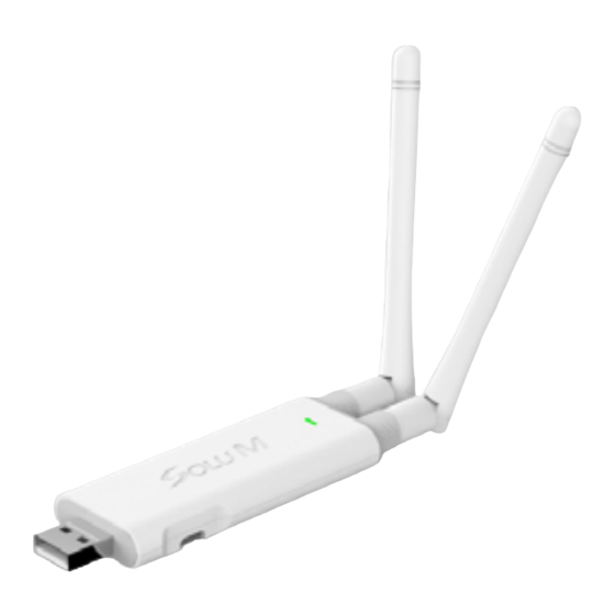
4. Product Description 4-1 Exterior 4.1.1 USB Gateway Status LED... -
Page 10: Usb Gateway
5. Op perati ing P Proced dure Operat tion Che 3-color LED D Status of f USB Gatew GREEN BLUE Status Comm ents Normal About 200ms, At bo oting time (200ms It mean ns USB GW is just rebooted Warnin Pressin ng factory rese et button and Turning on U USB GW If press sing the butto on more than 10 secs, facto ory mode will ... - Page 11 Blinking Normal Normal Mode (Webserver is working properly) (1sec) Blinking On/Off Normal Normal Mode (Webserver and RF Module are working (1sec) properly) ‐ Green Blinking (Normal Mode) ‐ Blue On for 10sec (Wakeup Mode On) periodically every 5 On Blinking Warning NTP failed (5 sec) (1sec) ‐ RED On for 5 sec periodically every 10 sec Blinking Warning Checking firmware update for 1 sec ~ 20 sec (200ms) Blue Blinking 200ms Blinking Blinking Warning Pressing factory reset button (250ms) (1sec) RED : 250ms , Green : 1 sec Blinking Warning Activating Factory Reset mode (Resetting configuration files) (1sec) Warning Downloading firmware file from Server and updating firmware (Long) Blinking Warning Writing RF Firmware to RF MODEM ...
- Page 12 (3) Indu ustrial PDA b) Regi ster produc t and tag m apping info ormation. Usin ng the PDA A’s WLAN f feature, regi ister mappin ng data with h the 4) Serv ver. (4) Serv 12 2...
- Page 13 c) Atta ach a back r rail to the sh helf (secure using doub ble-sided tap pe or screws d) Atta ach end and d middle cap ps to the mi iddle rail. e) Tak ke a tag that has been m mapped from m step a) and d insert to th...
- Page 14 NOTE : This equipment has been tested and found to comply with the limits for a Class B digital device, pursuant to part 15 of the FCC Rules. These limits are designed to provide reasonable protection against harmful interference in a residential installation This equipment generates, uses and can radiate radio frequency energy and, if not installed and used in accordance with the instructions, may cause harmful interference to radio communications, However, there is no guarantee that interference will not occur in a particular installation.
Need help?
Do you have a question about the SLG-DM101 and is the answer not in the manual?
Questions and answers