
Subscribe to Our Youtube Channel
Related Manuals for LMI LIQUITRON DP5000 Series


Summary of Contents for LMI LIQUITRON DP5000 Series
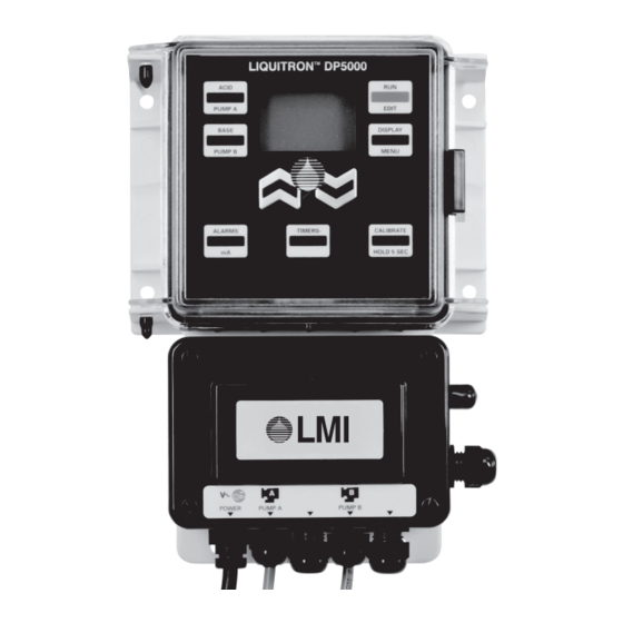
- Page 1 LIQUITRON™ DP5000 Series pH Controller Instruction Manual Manual No : 1756 Rev. Rev. Date : 5/2019...
-
Page 3: Table Of Contents
TABLE OF CONTENTS 1.0 INTRODUCTION ............... 1 2.0 UNPACKING . - Page 4 LIST OF ILLUSTRATIONS FIGURE 1. Unpacking Items ..............2 FIGURE 2.
-
Page 5: Introduction
SECTION 1 - INTRODUCTION The LIQUITRON™ DP5000 Series pH Controllers The controller is compatible with any pH electrode are designed for a variety of industrial pH that generates a mV signal and allows incorporation applications including metal finishing, water of platinum 1000 W automatic temperature treatment, printed circuit board manufacturing and compensation (ATC) elements. -
Page 6: Unpacking
Contact your LMI Distributor if any of the instruction manual. -
Page 7: Installation
SECTION 3 - INSTALLATION 3.1 PRE-INSTALLATION 3.4 MOUNTING THE ELECTRONIC ENCLOSURE BE SURE THAT THE UNIT HAS A PLUG AND VOLTAGE CODE The LIQUITRON™ DP5000 control module is COMPATIBLE WITH THE POWER SOURCE THAT YOU INTEND supplied with integral wall mounting flanges. It TO USE. -
Page 8: Figure 3A. Typical In-Line Installation
pH ELECTRODE FLOW FLOW Optional Preamp. and Cable DP5000 PUMP PUMP pH CONTROLLER BASE (ALKALAI) ACID SOLUTION SOLUTION Figure 3A. Typical In-Line Installation DP5000 pH CONTROLLER PUMP PUMP OPTIONAL PREAMPLIFIER INFLUENT ACID BASE (ALKALAI) SOLUTION SOLUTION ELECTRODE EFFLUENT BATCH TANK Figure 3B. -
Page 9: Electrical Installation
SECTION 3 - INSTALLATION 3.5 ELECTRICAL INSTALLATION Connect the pH adjustment pump(s) to the terminal strip for ‘ON / OFF’ control (connect to 3.5.1 Electrical Connections receptacles directly for 115 V models) or to cables TO REDUCE THE RISK OF for ‘PROPORTIONAL’... -
Page 10: Figure 4. Electrode And Pump Connections
ON / OFF Proportional 12in (304.8mm) 10ft (3m) pH Electrode (BNC Connector) Output Wiring Power Cord for Options 6ft (1.8m) BOTTOM VIEW Input / Output Wiring for Options Power Cord Base Pump Output* Acid Pump Output* Figure 4. Electrode and Pump Connections Instruction Manual... -
Page 11: Figure 5. Terminal Strip
Voltage Selection Switch Terminal Strip Wiring Fuse #2 SCREWDRIVER Fuse #1 WIRE SCREWDRIVER See Detail A WIRE Detail A Live Output 120V/230V 4-20mA Alarm 1 PreAmp Output Power Temp Alarm 2 Temp Neutral Output Input Temp Pump B Output Solenoid Pump A Output Fault... -
Page 12: Terminal Board Signal Description
SECTION 3 - INSTALLATION 3.5.2 Terminal Board Signal Description Terminal blocks are TB1-TB4 from left to right, and Pin 1 is at the bottom of each terminal block. Pin 1-Pin 3 Earth connection (one for input power connection) Neutral power connection (one for input power TB1 Terminal Strip Pin 4-Pin 9 connection) -
Page 13: Field Wiring Instructions
SECTION 3 - INSTALLATION 3.5.3 Field Wiring Instructions Alarm relays 1 and 2 are provided to signal an out of tolerance condition externally. These are Typical US field installation would include a Form C contacts, providing a common, a normally 6 ft (2 m) AC cord wired and two (2) 1 ft (30 cm) open and a normally closed connection. -
Page 14: Ph Adjustment Pump(S)
150% of the maximum pumping MENU requirement. Install and calibrate the pumps PUMP B according to the manufacturer’s recommendations. The Proportional Output DP5000 pH Controller will operate any LMI AA9, AA7, B9, B7, C9, C7 ® CALIBRATE ALARMS - TIMERS -... - Page 15 SECTION 3 - INSTALLATION This key is used to program ‘run times’ Pressing this key will cause the display - TIMERS - DISPLAY for Pumps A and B, ‘delay times’ to alternate showing various settings. 1 and 2 for actuating and controlling a (Holding the key for five (5) seconds will solenoid valve (when programmed ‘ON’...
-
Page 16: Operation
SECTION 4 - OPERATION 4.1 DEFAULT SETTINGS When the unit is plugged in, the computer powers up and the display illuminates. The display flashes In the default mode, as shipped from the factory the pH reading and ‘OFF’. This indicates the pumps without any extended features programmed in will not operate and the unit is in the ‘OFF’... -
Page 17: Proportional Mode
SECTION 4 - OPERATION NOTE: Pressing switches the mode back and forth Throughout this manual, the term ‘pulse’ is used EDIT from RUN’ to ‘OFF’. The pH set points and pump to describe the mechanical stroke of the pump, as strokes per minute (SPM). speed (pulses/min) can be changed only in the ‘OFF’... -
Page 18: On / Off Mode
SECTION 4 - OPERATION 4.1.2 ON / OFF Mode ACID 5. Press again. PUMP A 6. Press to increase / decrease the pH Hysteresis Alarm 1 Alarm 2 for Set Point 2. 12.5 Pump A Point 2 10.5 Pump B Pump A ACID 7. - Page 19 SECTION 4 - OPERATION It is highly recommended that the hysteresis (pump ACID 3. Press to save programmed Set Point. OFF function) be used to prevent relay chatter. PUMP A 4. Press to program Δ pH (Hysteresis) The function of the hysteresis is to prevent pump period for relay.
-
Page 20: Alarms
SECTION 4 - OPERATION 4.2 ALARMS If the 4-20 mA option board is installed, the following screens will appear. If these do not appear NOTE: and the 4-20 mA PCB is installed, go to Section Controller must be in ‘OFF’ mode to program 4.6, Advanced Menu, and program option “7”... -
Page 21: Calibration (Viewing Last Calibration Data)
Point 2 current calibration. NOTE: If the LMI temperature cable and probe are ® connected, then the computer automatically selects and uses this ATC (automatic temperature compensation) during calibration. - Page 22 SECTION 4 - OPERATION Calibration (e.g., 2 Point) It is not possible to program temperature if ‘ATC’ CALIBRATE is selected. + 5 seconds HOLD 5 SEC Hold the ‘CALIBRATE’ key down for five (5) NOTE: seconds. ‘CALIBRATE’ will start flashing. Automatic temperature probe detection can be over-ridden in pH calibration mode.
-
Page 23: Pump Timers And Solenoid Valve Control Timers
SECTION 4 - OPERATION 4.5 PUMP TIMERS AND SOLENOID CALIBRATE 8. Press again and the symbol will VALVE CONTROL TIMERS HOLD 5 SEC prompt you to put the probe in ‘Buffer 2’. Wait It is not possible to change timer values while in for the mV value to settle. -
Page 24: Setting Timers
SECTION 4 - OPERATION 4.5.3 Setting Timers 4.5.4 Solenoid Valve Control - TIMERS - 5. Press the key to advance to ‘Delay 1’ time NOTE: (if activated). ‘Delay 1’ is the wait time after pH The unit must be in the ‘OFF’ (edit) mode to change the timer settings. -
Page 25: Display Key
SECTION 4 - OPERATION The smoothing of the input signal is determined by 4.5.5 Display Key DISPLAY delta (pH) time. The ‘Response Rate’ is the time While in the Run Mode the key can be that the computer display takes before it updates pressed once to display current parameters. -
Page 26: Advanced Menu
SECTION 4 - OPERATION 4.6 ADVANCED MENU Similarly, the Pump Control Points can be displayed while in the ‘RUN’ Mode by pressing the ‘Pump A’ DISPLAY Holding the key for five (5) seconds accesses or ‘Pump B’ keys once. the ‘Advanced Features’ Menu, and allows these ACID Press and the following screens display:... -
Page 27: Maintenance
SECTION 5 - MAINTENANCE 5.1 pH ELECTRODE AND CABLE The most frequently replaced part is the pH electrode, which will deteriorate with age. Refillable electrodes should be checked for level frequently, and replenished with filling solution as necessary. An electrode may also fail because of: 1. -
Page 28: Troubleshooting
SECTION 6 - TROUBLESHOOTING Troubleshooting and repair of the malfunctioning unit should only be attempted by qualified personnel using caution to ensure safety and limit unnecessary damage. Should an error or alarm condition occur, the controller will alert the operator by flashing an ‘ERROR MESSAGE’. -
Page 29: Dp5000 Specifications
SECTION 7 - DP5000 SPECIFICATIONS 115 VAC ±15%, 60 Hz Power Requirements 230 VAC ±15%, 50 Hz Voltage input selectable via a selector switch located on the I/O PCB. Flow Switch, Remote ON / OFF, Spares. Inputs All low voltage inputs active low, i.e., the active state is when the switch is closed. The switch must be capable of switching 2 mA at ±... - Page 30 SECTION 7 - DP5000 SPECIFICATIONS Operating Voltage: 5 V Operating Temperature 32° F to +122° F (0° C to +50° C) Viewing Area: 1.2 x 1.8 inches (30 x 46 mm) LCD Display Backlight: An 8 emitter (dual LED type), double row, reflective backed, backlight module will be used.
-
Page 31: Program Log
SECTION 8 - PROGRAM LOG For record keeping, a program log is provided below. Proportional Proportional ON / OFF ON / OFF Pt 1 Pt 2 Pt 1 Pt 2 Pump A Set Point 10.5 Pump A Pulses/Min Pump B Set Point Pump B Pulses/Min Hysteresis 1 Hysteresis 2... -
Page 32: Parts List
Cover, Utility Box 30588 Label LMI Logo 37524 Front Panel Assembly 31617 Cover, Liquitron™ 32094 Label, Housing cover LMI 32211 Cap, 0.125 x 0.38 32352 O-Ring, Sponge 32395 Screw, Self-Tapping 48461 Cord, Power, 115V, NEMA 15-R - DP5000-XA (ON / OFF) -
Page 33: Exploded View
SECTION 10 - EXPLODED VIEW 115V PROPORTIONAL (U.S. VERSION ONLY) CONTROL ON / OFF CONTROL Instruction Manual... - Page 36 is a registered trademark of Milton Roy, LLC. ® LIQUITRON™ is a trademark of Milton Roy, LLC. © 2015 Milton Roy, LLC. info@miltonroy.com www.lmipumps.com...
Need help?
Do you have a question about the LIQUITRON DP5000 Series and is the answer not in the manual?
Questions and answers