Table of Contents
Advertisement
For file reference, please record the following data:
Model No:
Serial No:
Installation Date:
Installation Location:
When ordering replacement parts for your LMI Controller or accessory, please include the
complete Model Number and Serial Number of your unit.
Instruction
Liquitron™ DR5000 Series
ORP (Redox) Controller
Manual
8 Post Office Square
Acton, MA 01720 USA
TEL: (978) 263-9800
FAX: (978) 264-9172
http://www.Imipumps.com
Replaces same of Rev. D 1/98
1761. E 9/99
1
Advertisement
Table of Contents

Subscribe to Our Youtube Channel
Related Manuals for LMI Liquitron DR5000-1A


Summary of Contents for LMI Liquitron DR5000-1A
- Page 1 Model No: Serial No: Installation Date: Installation Location: When ordering replacement parts for your LMI Controller or accessory, please include the complete Model Number and Serial Number of your unit. 8 Post Office Square Acton, MA 01720 USA TEL: (978) 263-9800 FAX: (978) 264-9172 http://www.Imipumps.com...
-
Page 2: Table Of Contents
Contents Introduction ............................3 Unpacking ............................3 Installation ............................4 3.1 Mounting the Electronic Enclosure ..................4 3.2 Electrical Installation ......................6 3.2.1 Terminal Board Signal Description ................7 3.2.2 Field Wiring Instructions (Optional 4-20 mA Output) ..........8 3.3 ORP Adjustment Pump(s) ....................9 3.4 Keypad and Display ....................... -
Page 3: Introduction
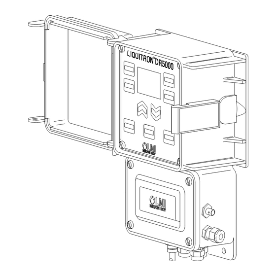
Your carton will contain the items shown in Figure 1. Please notify the carrier immediately if there are any signs of damage to the Controller or its parts. Contact your LMI Distributor if any of the parts are missing. There is a number label on the inside cover of the unit; for easy reference, you should note the model and serial numbers on the front cover of this instruction manual. -
Page 4: Installation
Installation Pre-Installation Cord & Voltage Code Be sure that the unit has a plug and voltage code compatible with the power source that you intend to use. CAUTION Environment: The housing is corrosion and spray resistant but should not be subjected to excessive spray or ambient temperature over 122°... - Page 5 Figure 3A: Typical In-Line Installation Figure 3B: Typical Batch Installation...
-
Page 6: Electrical Installation
Electrical Installation ELECTRICAL CONNECTIONS To reduce the risk of electrical shock, the control or metering pump must be plugged into a grounded outlet with ratings conforming to the data on the control panel. It must be connected to a good ground. DO NOT USE CAUTION ADAPTERS! All wiring must conform to local electrical codes. -
Page 7: Terminal Board Signal Description
Terminal Strip Wiring Figure 5: Terminal Strip 3.2.1 Terminal Board Signal Description Terminal blocks are TB1-TB4 from left to right, and Pin 1 is at the bottom of each terminal block. TB1 Terminal Strip Pin 1-Pin 3 ..Earth connection (one for input power connection) Pin 4-Pin 9 .. -
Page 8: Field Wiring Instructions (Optional 4-20 Ma Output)
3.2.2 Field Wiring Instructions Typical US field installation would find a 6 ft (2 m) AC cord wired and two (2) 1 ft (30 cm) AC receptacles (On/Off mode) or two (2) 10 ft (3 m) pump drive cables (Proportional mode) installed. A BNC receptacle would be installed for the ORP probe. -
Page 9: Orp Adjustment Pump(S)
Install and calibrate the pumps according to the manufacturer’s recommendations. In the Proportional Output mode, the DR5000 ORP Controller will operate any LMI Series A9, A7, B9, B7, C9, C7, E7 or L7 pump, or any other pump which operates by providing direct proportional response to a modulated pulse input signal. - Page 10 KEYS: This key is used to set up the control profile for the reducer dosing pump (holding the key for five (5) seconds will allow priming of Pump A) (Factory setting 90 SPM). This key is used to set up the control profile for the oxidizer dosing pump (holding the key for five (5) seconds will allow priming of Pump B) (Factory setting 65 SPM).
-
Page 11: Operation
OPERATION In the default mode, as shipped from the factory without any extended features programmed in the ‘menu’, the controller is set to operate two dosing pumps towards a single desired ORP region as defined by the set points. It will do this in one of two ways, On/Off or Proportional, shown graphically below: On/Off Control Proportional... -
Page 12: Proportional Mode
Proportional Mode The unit is shipped pre set at the factory for the Proportional or On/Off mode. To change the unit to the opposite mode see ‘Advanced List,’ Option 2, on page 20. Pump A Control Profile Controller must be in Off mode to program changes. -
Page 13: On/Off Mode
(9) ..Pump B (Oxidizer Pump) is programmed in a similar way. If ‘Point 3’ is selected in the Advanced Features menu, the user will be prompted to enter a ORP value for Set Point 3 and a Pump Speed at Set Point 3. On / Off Mode (50 mV) Pump A Control Profile... -
Page 14: Alarms
It is highly recommended that the hysteresis (pump off function) be used to prevent relay chatter. The function of the hysteresis is to prevent pump relay chattering. It operates by allowing the pump to be turned on when the control point plus (or minus) the hysteresis value has been met, but does not allow the pump to turn off until the control point has been met. -
Page 15: Calibration (Viewing Last Calibration Data)
(8) ..Press again to program the 4-20 mA output for Point 1. (9) ..Press to select the mV value for Point 1 mA output. Default is: 4 mA = - 1000mV 20 mA = +1000 mV (10) ..Press again. -
Page 16: Performing A New Calibration
Performing a New Calibration For two point calibration, the default settings are Buffer 1 = 80.0 mV and Buffer 2 = 400 mV; but these values may be changed. The calibration parameters (buffer mV and one or two point calibration) of the previous calibration are the initial values for the current calibration. -
Page 17: Pump Timers And Solenoid Valve Control Timers
(6) ..Press again and the symbol will prompt you to put the probe in Buffer 2. Wait for the mV value to settle. (7) ..Press again. This will accept the second calibration value and will display the mV/mV and % Slope result of the calibration. - Page 18 Setting Timers The unit must be in the Off (edit) mode to change the timer settings. (1) ..Press the key to view the run time for Pump A. (2) ..Use to adjust to desired maximum run time. The ‘hr : min’ will change to ‘min : sec’ automatically as the run time is reduced below 1 hour. (3) ..
- Page 19 (7) ..Press key to advance to Response Rate. This is programmed in D ORP units. The smoothing of the input signal is determined by D ORP time. The following values can be programmed (min : sec): 00 : 01, 00 : 10, 00 : 20,..04 : 00 (In increments of 10 seconds) When 00 : 01 is programmed the controller responds to a change in input in one (1) second.
-
Page 20: Advanced Menu List
Advanced Menu List Holding the key for five (5) seconds allows programming of Advanced Features in a Menu. The menu can be accessed by pressing the Display/Menu key for five (5) seconds while the controller is in the Edit or Off mode. The first item displayed is the software revision. -
Page 21: Troubleshooting
Troubleshooting Error Messages Troubleshooting and repair of the malfunctioning unit should only be attempted by qualified personnel using caution to ensure safety and limit unnecessary damage. Should an error or alarm condition occur, the controller will alert the operator to this by flashing an Error Message. These messages are depicted below with a brief explanation. -
Page 22: Dr5000 Specifications
DR5000 Specifications Power Requirements ____ 115 VAC ±15%, 60 Hz 230 VAC ±15%, 50 Hz Voltage input selectable via a selector switch located on the I/O PCB. Inputs ________________ Flow Switch, Remote On/Off, Spares. All low voltage inputs active low, i.e., the active state is when the switch is closed. - Page 23 LCD Display Operating Voltage: Operating Temperature 32° F to +122° F (0° C to + 50° C) Viewing Area: 1.2 x 1.8 inches (30.5 mm x 45.7 mm) Backlight: An 8 emitter (dual LED type), double row, reflective backed, backlight module will be used.
-
Page 24: Parts List
Gasket, Foam 34088 Cover, Utility Box 30588 Label, LMI Logo 37526 Front Panel Assembly 31617 Cover, Liquitron™ 32094 Label, Housing cover LMI 32211 Cap, .125 x .38 32352 O-Ring, Sponge 32395 Screw, Self-Tapping 34911 Cover, Fuse 35711 Cord, Power, 115V, NEMA 15-R - DR5000-XA (On/Off) -
Page 25: Exploded View
Exploded View... -
Page 26: Program Log
10.0 Program Log For record keeping, a program log is provided below. Proportional On/Off Proportional On/Off Pt 1 Pt 2 Pt 1 Pt 2 Pump A Set Point Pump A Pulses/Min / / / / / / Pump B Set Point -100 -750 -100... -
Page 27: Statement Of Limited Warranty
11.0 Statement of Limited Warranty LMI TERMS AND CONDITIONS OF SALE: 1. Seller warrants that the equipment delivered by it to the Buyer is in accordance with the Seller’s published specifications and is of the kind and of the description contained in seller’s invoice. - Page 28 8 Post Office Square Acton, MA 01720 USA TEL: (978) 263-9800 FAX: (978) 264-9172 http://www.Imipumps.com Liquitron is a trademark of Liquid Metronics, Inc. © 1999 LMI Milton Roy - All Rights Reserved Printed in USA Specifications subject to change without notice.
Need help?
Do you have a question about the Liquitron DR5000-1A and is the answer not in the manual?
Questions and answers