Table of Contents
Advertisement
For file reference, please record the following data:
Model No:
Serial No:
Installation Date:
Installation Location:
When ordering replacement parts for your LMI Controller or accessory, please include
the complete Model Number and Serial Number of your unit.
Instruction
Instruction
Instruction
Instruction
Instruction
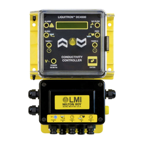
Liquitron™ DC4500 Series
sales@novatech-usa.com
www.novatech-usa.com
Tel: (866) 433-6682
Fax: (866) 433-6684
Tel: (281) 359-8538
Fax: (281) 359-0084
Manual
Manual
Manual
Manual
Manual
Replaces same of Rev. C 7/97
1780.D 7/00
Advertisement
Table of Contents

Subscribe to Our Youtube Channel
Related Manuals for LMI Liquitron DC4500 Series


Summary of Contents for LMI Liquitron DC4500 Series
- Page 1 For file reference, please record the following data: Model No: Serial No: Installation Date: Installation Location: When ordering replacement parts for your LMI Controller or accessory, please include the complete Model Number and Serial Number of your unit. sales@novatech-usa.com www.novatech-usa.com Tel: (866) 433-6682...
-
Page 2: Table Of Contents
(866) 433-6682 • (281) 359-8538 • sales@novatech-usa.com • www.novatech-usa.com Contents Introduction ........................... 4 Installation ..........................6 Mounting the Controller Enclosure ................ 6 Enclosure Mounting Dimensions ................7 Electrical Wiring Information ................... 8 Terminal Strip Layout ....................9 Operating the Controller ...................... 13 Menu Overview ..................... -
Page 3: Introduction
DC4500 will control conductivity and chemical feed in cooling towers and closed loop systems. LMI’s DC4500 Series of conductivity controllers allows the greatest programming flexibility for cooling tower system applications. This is accomplished through the use of an extensive options menu that is easy to use. - Page 4 (866) 433-6682 • (281) 359-8538 • sales@novatech-usa.com • www.novatech-usa.com All setpoints and parameter settings are retained permanently in a special nonvolatile computer chip memory, preventing their loss due to a power outage. This nonvolatile memory chip allows the unit to be programmed before installation.
-
Page 5: Installation
(866) 433-6682 • (281) 359-8538 • sales@novatech-usa.com • www.novatech-usa.com An analog data (or control) output is provided. This is a non-isolated 4 - 20 mA signal. The conductivity reading that corresponds to minimum and maximum analog signals is fully adjustable. This signal can be used to power chart recorders or other pumps and devices. -
Page 6: Enclosure Mounting Dimensions
(866) 433-6682 • (281) 359-8538 • sales@novatech-usa.com • www.novatech-usa.com 2.2 Enclosure Mounting Dimensions When using the prewired unit, the enclosure is configured as NEMA 12X. If the unit is connected through watertight conduit, the enclosure is configured as NEMA 4X. The following clearances should be observed for proper mounting (see Figures 2 and 3). -
Page 7: Electrical Wiring Information
(866) 433-6682 • (281) 359-8538 • sales@novatech-usa.com • www.novatech-usa.com 2.3 Electrical Wiring Information To reduce the risk of electrical shock, the controller must be plugged into a grounded outlet with ratings conforming to the specifications on the data nameplate. It must be connected to a viable ground circuit. DO NOT USE ADAPTERS (see Figure 4)! All wiring must conform to required electrical codes. -
Page 8: Terminal Strip Layout
(866) 433-6682 • (281) 359-8538 • sales@novatech-usa.com • www.novatech-usa.com 2.4 Terminal Strip Layout To access the wiring connections inside of the conductivity controller: 1. Disconnect the unit from electrical power. 2. Remove the four (4) screws and the junction box cover on the lower half of the unit. 3. - Page 9 (866) 433-6682 • (281) 359-8538 • sales@novatech-usa.com • www.novatech-usa.com 4 - 20 mAmp Output 4 - 20 mAmp Output 4 - 20 mAmp Output 4 - 20 mAmp Output 4 - 20 mAmp Output ( + ) TB9-1 ( - ) TB9-2 Biocide #1 Pump Output Biocide #1 Pump Output...
- Page 10 (866) 433-6682 • (281) 359-8538 • sales@novatech-usa.com • www.novatech-usa.com Thermistor Probe Output (Hardwire Only) Thermistor Probe Output (Hardwire Only) Thermistor Probe Output (Hardwire Only) Thermistor Probe Output (Hardwire Only) Thermistor Probe Output (Hardwire Only) Run the thermistor probe wiring through the PG9 connector on the right side of the DC4500 controller junction box keeping the wires away from any 115/230 VAC cables that may cause electrical interference.
- Page 11 (866) 433-6682 • (281) 359-8538 • sales@novatech-usa.com • www.novatech-usa.com Figure 5: Bottom of controller with cover open. Figure 5: Bottom of controller with cover open. Figure 5: Bottom of controller with cover open. Figure 5: Bottom of controller with cover open. Figure 5: Bottom of controller with cover open.
- Page 12 (866) 433-6682 • (281) 359-8538 • sales@novatech-usa.com • www.novatech-usa.com ALARM TEST SWITCH CHART RECORDER AC POWER TEST 4-20 MILLIAMP FUSE OUTPUT LINE(N.O.) LINE(N.C.) TBIO NEUTRAL MOTORIZED VALVE TB11 FLOWMETER MAIN POWER INPUT FLOW SWITCH WHITE GRAY SOLENOID VALVE BLACK PROBE FEED BIO 2 BIO 1...
- Page 13 (866) 433-6682 • (281) 359-8538 • sales@novatech-usa.com • www.novatech-usa.com ALARM TEST SWITCH CHART RECORDER AC POWER TEST 4-20 MILLIAMP FUSE OUTPUT TBIO TB11 AC POWER SOLENOID VALVE FLOWMETER MAIN POWER INPUT FLOW SWITCH WHITE GRAY LINE(N.O.) LINE(N.C.) NEUTRAL BLACK PROBE MOTORIZED VALVE FEED...
-
Page 14: Operating The Controller
(866) 433-6682 • (281) 359-8538 • sales@novatech-usa.com • www.novatech-usa.com 3.0 Operating the Controller The Conductivity Read Screen or “System Run”: C C C C C OND: OND: OND: OND: µ S 1 470 OND: The normal operating display for the DC4500 Series Controller is the conductivity reading screen as (shown above). -
Page 15: Menu Overview
(866) 433-6682 • (281) 359-8538 • sales@novatech-usa.com • www.novatech-usa.com 3.1 Menu Overview When the “System Run” screen is displayed in the window, the unit automatically switches to the run/operate mode of operation. COND: COND: 1470 1470 COND: COND: COND: µ S 1470 1470 1470... - Page 16 (866) 433-6682 • (281) 359-8538 • sales@novatech-usa.com • www.novatech-usa.com 3.2 Conductivity CONDUCTIVITY COND COND µ µ µ µ µ S)3400 S)3400 S)3400 COND COND COND S)3400 S)3400 Conductivity Reading Screen Conductivity Reading Screen Conductivity Reading Screen Conductivity Reading Screen Conductivity Reading Screen SET POINT The “CONDUCTIVITY”...
-
Page 17: Conductivity
(866) 433-6682 • (281) 359-8538 • sales@novatech-usa.com • www.novatech-usa.com 3.3 Set Point CONDUCTIVITY 3000 3000 3000 3000 3000 Set Point Screen Set Point Screen Set Point Screen Set Point Screen Set Point Screen SET POINT The “SET POINT” screen allows access to the conductivity value that will energize the bleed output relay and allow for the opening of the bleed valve. -
Page 18: Set Point
(866) 433-6682 • (281) 359-8538 • sales@novatech-usa.com • www.novatech-usa.com 3.4 D D D D D Differential ∆ ∆ ∆ ∆ ∆ DIFF CONDUCTIVITY DIFF DIFF DIFF DIFF 100 00 00 00 00 Differential or Dead Band Differential or Dead Band Differential or Dead Band Differential or Dead Band Differential or Dead Band... -
Page 19: Differential
(866) 433-6682 • (281) 359-8538 • sales@novatech-usa.com • www.novatech-usa.com 3.5 Low Alarm CONDUCTIVITY LO ALARM LO ALARM LO ALARM LO ALARM LO ALARM Low Conductivity Alarm Set Point Low Conductivity Alarm Set Point Low Conductivity Alarm Set Point Low Conductivity Alarm Set Point Low Conductivity Alarm Set Point SET POINT The “LOW ALARM”... -
Page 20: Low Alarm
(866) 433-6682 • (281) 359-8538 • sales@novatech-usa.com • www.novatech-usa.com 3.6 High Alarm CONDUCTIVITY HI ALARM HI ALARM HI ALARM 4000 4000 4000 HI ALARM HI ALARM 4000 4000 High Conductivity Alarm Set Point High Conductivity Alarm Set Point High Conductivity Alarm Set Point High Conductivity Alarm Set Point High Conductivity Alarm Set Point SET POINT... -
Page 21: High Alarm
(866) 433-6682 • (281) 359-8538 • sales@novatech-usa.com • www.novatech-usa.com 3.7 Feed CONDUCTIVITY FEED FEED FEED FEED FEED (MODE) (MODE) (MODE) (MODE) (MODE) Feed Pump Screen Feed Pump Screen Feed Pump Screen Feed Pump Screen Feed Pump Screen SET POINT The “FEED” screen displays the current Inhibitor Feed Pump mode selected. -
Page 22: Feed
(866) 433-6682 • (281) 359-8538 • sales@novatech-usa.com • www.novatech-usa.com 3.8 Clock CONDUCTIVITY WEEK WEEK WEEK WEEK WEEK 16:05 16:05 16:05 16:05 16:05 SET POINT The “CLOCK” screen displays the current week, day, and time. The time is based on a 24-hour clock. The number week that is displayed reflects the current week during the selected biocide programming based on a 1, 2, 3, or 4 week repeating cycle. -
Page 23: Clock
(866) 433-6682 • (281) 359-8538 • sales@novatech-usa.com • www.novatech-usa.com 3.9 View Biocide VIEW VIEW VIEW VIEW VIEW BIOCIDE BIOCIDE BIOCIDE BIOCIDE BIOCIDE Review Current Programmed Biocides Review Current Programmed Biocides Review Current Programmed Biocides Review Current Programmed Biocides Review Current Programmed Biocides CONDUCTIVITY The “VIEW BIOCIDE”... -
Page 24: View Biocide
(866) 433-6682 • (281) 359-8538 • sales@novatech-usa.com • www.novatech-usa.com 3.10 Add Biocide CONDUCTIVITY BIOCIDE BIOCIDE BIOCIDE BIOCIDE BIOCIDE SET POINT Biocide pump “on” times may be programmed or added in this main menu selection screen. Press “ENTER” to access the sub-menu screens that allow the programming options for each Biocide pump. -
Page 25: Add Biocide
(866) 433-6682 • (281) 359-8538 • sales@novatech-usa.com • www.novatech-usa.com 3.11 Biocide Lockout CONDUCTIVITY BIOS BIOS BIOS BIOS BIOS LOCKOUT LOCKOUT LOCKOUT LOCKOUT LOCKOUT SET POINT The “BIOCIDE LOCKOUT” screen selection allows for the program- ming of a system Bleed lockout time. This option prevents the bleed of a cooling tower immediately following chemical biocide addition. -
Page 26: Biocide Prebleed
(866) 433-6682 • (281) 359-8538 • sales@novatech-usa.com • www.novatech-usa.com 3.12 Biocide Prebleed CONDUCTIVITY BIOS BIOS BIOS BIOS BIOS PREBLEED PREBLEED PREBLEED PREBLEED PREBLEED Biocide Prebleed Screen Biocide Prebleed Screen Biocide Prebleed Screen Biocide Prebleed Screen Biocide Prebleed Screen SET POINT The Biocide pump “PREBLEED”... -
Page 27: Manual Outputs
(866) 433-6682 • (281) 359-8538 • sales@novatech-usa.com • www.novatech-usa.com 3.13 Manual Outputs CONDUCTIVITY MANUAL MANUAL OUTPUT OUTPUT MANUAL MANUAL MANUAL OUTPUT OUTPUT OUTPUT Manually Energize Relay Outputs Manually Energize Relay Outputs Manually Energize Relay Outputs Manually Energize Relay Outputs Manually Energize Relay Outputs SET POINT The “MANUAL OUTPUTS”... - Page 28 (866) 433-6682 • (281) 359-8538 • sales@novatech-usa.com • www.novatech-usa.com 3.14 Advanced Setup ADVANCED ADVANCED SETUP SETUP ADVANCED ADVANCED ADVANCED SETUP SETUP SETUP CONDUCTIVITY The “ADVANCED SETUP” screens allow for the special configuring of the controller for advanced options. These options include: SET POINT •...
-
Page 29: Advanced Setup
(866) 433-6682 • (281) 359-8538 • sales@novatech-usa.com • www.novatech-usa.com 3.15 Temperature CONDUCTIVITY 032° ° ° ° ° TEMP (F) TEMP (F) TEMP (F) TEMP (F) TEMP (F) SET POINT The “TEMPERATURE” screen displays the temperature sensed by the externally connected thermistor [10K Ohms at 77° F / 25° C]. The screen may display temperature in either Degrees (F) or Degrees (C). -
Page 30: Temperature
(866) 433-6682 • (281) 359-8538 • sales@novatech-usa.com • www.novatech-usa.com 3.16 H O Meter CONDUCTIVITY TOTAL TOTAL (00000) (00000) TOTAL TOTAL TOTAL (00000) (00000) (00000) Water Meter Totalizer Screen Water Meter Totalizer Screen Water Meter Totalizer Screen Water Meter Totalizer Screen Water Meter Totalizer Screen SET POINT The “WATER METER TOTAL”... -
Page 31: Start-Up
(866) 433-6682 • (281) 359-8538 • sales@novatech-usa.com • www.novatech-usa.com 4.0 Start-Up 4.1 Cooling Tower Installation The DC4500 Series of conductivity controller should be installed based upon the recommended system diagram below. A bypass loop for open recirculating water systems is the best method of conductivity monitoring and control. -
Page 32: Cooling Tower Start-Up
On/Off mode requires the pump to be connected to the ‘FEED L’ and any ‘AC NEUT’ terminal connection on the pc board. If an LMI ‘7’ or ‘9’ series pump is being used the pump stroking speed may be directly controlled by the DC4500 pulsed output. - Page 33 (866) 433-6682 • (281) 359-8538 • sales@novatech-usa.com • www.novatech-usa.com The DC4500 controller can be configured to control dual-chemical (biocide) pumps for water con- tamination/biological growth control based on a selectable 1-4 week timer. Use the table below to assist in setting up the program operating periods for the pumps when using the 1-4 week timer option.
- Page 34 (866) 433-6682 • (281) 359-8538 • sales@novatech-usa.com • www.novatech-usa.com Once the operating settings and parameters have been determined by the data entered in the previous pages, the DC4500 Controller can then be programmed. Supply power to the controller. Read the conductivity and verify the accuracy using a calibrated meter and conductivity sample.
-
Page 35: Bleed Sampling Option
(866) 433-6682 • (281) 359-8538 • sales@novatech-usa.com • www.novatech-usa.com 4.3 Bleed or Blowdown Sampling Option Operating Mode The DC4500 Conductivity Controller can be configured to operate in one (1) of two (2) different operating modes for conductivity bleed or blowdown: (1) Timed Conductivity Blowdown Sampling (2) Continuous Conductivity Blowdown Sampling (Standard Method) The Continuous Conductivity Bleed/Blowdown is the most commonly used method. -
Page 36: Calibration
(866) 433-6682 • (281) 359-8538 • sales@novatech-usa.com • www.novatech-usa.com 5.0 Calibration Calibration will be required during system start up or when a variation in conductivity readings exists between the displayed conductivity and the conductivity value determined from a reliable source (such as a hand held tester). -
Page 37: Maintenance
(866) 433-6682 • (281) 359-8538 • sales@novatech-usa.com • www.novatech-usa.com 6.0 Maintenance 6.1 Controller The DC4500 controller itself requires very little maintenance. Wiping the controller down with a damp cloth will clean it. Do not spray down the controller unless the enclosure door is closed and latched. 6.2 Probe The controller must be recalibrated after cleaning the probe. -
Page 38: Troubleshooting
Disconnect power to the controller before opening the front panel! Troubleshooting and repair of a malfunctioning controller should only be attempted by qualified personnel using caution to insure safety and to limit unnecessary further damage. Contact your local LMI distributor or the factory for assistance. PROBLEM... -
Page 39: Factory Settings
(866) 433-6682 • (281) 359-8538 • sales@novatech-usa.com • www.novatech-usa.com 8.0 Factory Settings Random Hour Random Minute Random Temperature Fahrenheit Conductivity Set point 2000 µS Delta Differential 100 µS Low Alarm 100 µS High Alarm 4000 µS Feed Mode Pulse Timer Pulse Timer 10 seconds Pulse Count... -
Page 40: Product Specifications
(866) 433-6682 • (281) 359-8538 • sales@novatech-usa.com • www.novatech-usa.com 9.0 Product Specifications 115 VAC +/-15%, 50/60 Hz Power Power Power Power Power Requirements Requirements Requirements 230 VAC +/-15%, 50/60 Hz Requirements Requirements Voltage input selectable via a selector switch located on the I/O PCB. Fuse: 4A 250 VAC Time Delay Flow Switch. -
Page 41: Product Exploded View
(866) 433-6682 • (281) 359-8538 • sales@novatech-usa.com • www.novatech-usa.com 10.0 Product Exploded View... -
Page 42: Product Parts List
(866) 433-6682 • (281) 359-8538 • sales@novatech-usa.com • www.novatech-usa.com 11.0 Product Parts List Item Item Item Part Part Part Item Item Part Part Description Description Description Description Description 35631 Housing, DC4500-100 & DC4500-200 35623 Housing, DC4500 - all others 32186 Screw, 4-40 x 0.37 32187 Nut, 4-40 flush... - Page 43 Tel: (866) 433-6682 Fax: (866) 433-6684 Tel: (281) 359-8538 Fax: (281) 359-0084 © 2000 LMI Milton Roy - All Rights Reserved Printed in USA Specifications subject to change without notice.
Need help?
Do you have a question about the Liquitron DC4500 Series and is the answer not in the manual?
Questions and answers