Table of Contents
Advertisement
Quick Links
Advertisement
Table of Contents

Related Manuals for OSTBERG HERU 400–2400T


Summary of Contents for OSTBERG HERU 400–2400T
- Page 1 U S E R M A N U A L | E N H E R U 4 0 0 - 2 4 0 0 T / S HERU T HERU S...
- Page 3 WARRANTY Warranty period valid according to purchase contract calculated from date of purchase. Unless otherwise agreed, the usual warranty period is two (2) years in accordance with NL01, amendment VU03. SCOPE OF WARRANTY The warranty covers faults occurring during the warranty period which are reported to the retailer, or which have been confirmed by H.
- Page 4 – The defective parts are handed over to the service partner for forwarding to the warrantor. – Repairs are started and work is carried out during normal working hours. For urgent repairs or repairs conducted outside normal working hours, the service partner is entitled to charge for extra costs.
-
Page 5: Table Of Contents
CONTENTS Scope of assembly/installation instructions ............. 9 Important information ................... 15 Abbreviations ........................15 Reference document ......................16 Flowchart and function descriptions............... 17 CONTROL DIAGRAM HERU® 400-2400 T/S ................17 CONTROL SYSTEM Function description ..............19 Password handling ....................24 Control unit HMI-TM .................... - Page 6 Unit consumption and output.* ..................41 Heating coil consumption and output................. 41 External components basic unit ................42 Temperature sensors ......................43 Internal temp. sensor ..................... 43 The supply air temperature sensor ..................43 Room temperature sensor ....................44 Outside temperature sensor ....................
- Page 7 Humidity sensor ........................75 External setpoint ........................76 Alarm input heating/cooling ....................77 Miscellaneous ...................... 79 Rotary heat exchanger control unit ..................79 Connection diagram ....................79 Functions ....................... 80 Operation indication in the control unit ............... 80 Time switch program ......................81 General .........................
- Page 8 Check Corrective action ....................... 107 Rotary heat exchanger ....................... 108 Function 108 Check Corrective action ....................... 108 Heating coil ........................110 Function 110 Check Corrective action ....................... 110 Pull out the coil........................110 Accessories ......................112 Accessory 112 Spare parts list ....................113 Troubleshooting ....................
-
Page 9: Scope Of Assembly/Installation Instructions
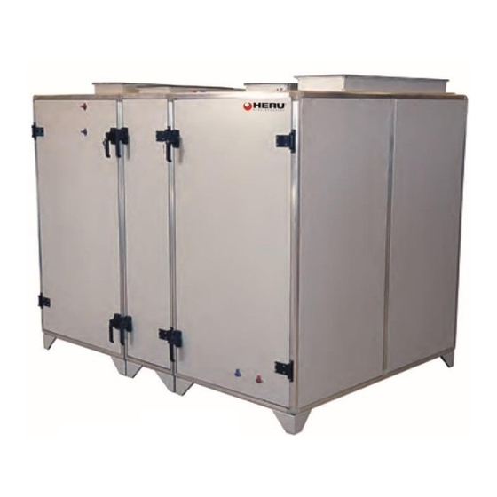
Scope of assembly/installation instructions ® HERU 400 – 2400 T/S DESCRIPTION OF UNIT DESCRIPTION OF UNIT • The HERU 400-2400 T/S energy recovery unit is designed for supply air and extract air ventilation with cooling and heat recovery. The unit is equipped with plug fans with maintenance-free EC motors and integrated heating function via water or electricity. - Page 10 •HERU is suitable for placement in warm areas. INSTALLATION AND SAFETY • For optimal indoor climate and to avoid moisture damage in the property, there must be continuous and adequate air exchange. The unit must be run continuously and only stopped for service.
- Page 11 • Do not use the safety switches for normal start and stop of the unit. • Electrical installation, electrical and mechanical work and work inside the unit and its peripheral equipment may only be performed by certified electricians or personnel designated by H.
- Page 12 ® ASSEMBLY AND INSTALLATION INSTRUCTIONS HERU 400-2400 T/S The base of the HERU T/S unit must be even and stable. Note and take into account the unit’s weight. 1. Always lift the unit using a pallet jack or truck with forks at least as long as the width of the unit.
- Page 13 FREE CLEARANCE FOR SERVICE AND OVERHAUL HERU T/S A=500 mm B=1200 m BEFORE STARTING Ensure that HERU® is correctly installed. Make sure that all ducts, water pipes and electrical connections are correctly assembled. Make sure no objects or dirt have entered the unit during construction, as this could lead to injury and/or damage to the unit.
- Page 14 14 / 120 Climatix HERU® 400-2400 2018-02-13 Scope of assembly/installation instructions...
-
Page 15: Important Information
Important information Information is provided for each individual function on the menu in the control unit/HMI. Because of this, the information in the example menu screenshots may not be consistent with the information provided in the HMI of each individual HERU® CX unit. Sometimes all of the rows of information are described, when in reality only a limited number of menu rows will be visible. -
Page 16: Reference Document
Reference document Document no. Document title Climatix Room unit POL822.60 (2-wire interface) 9720001 Climatix Basic Documentation 9720005 Climatix Modbus Guide & Reference List 9720006 Climatix LON Guide & SNVT List 9720007 Climatix BACnet/IP Guide & Object List 9720008 Climatix OPC Guide & Tag List 9720009 Climatix Advanced Web Module Guide 9720010... -
Page 17: Flowchart And Function Descriptions
Flowchart and function descriptions Important The flowchart and function descriptions describe most of the functions the controller can information handle. With regards to unit configuration, all functions may not be available in the supplied model. Some can be selected in the HMI and are then described as Optional in the HMI. - Page 18 Outside temp sensor EMS-RV Rotation monitor EMS Room unit Supply air pressure Circulation pump heating Supply-EC Supply air fan (TF) EC motor sensor Extract air pressure Circulation pump cooling Extract- Extract air fan (FF) EC motor sensor Supply air filter sensor SV1 Valve actuator heating Extract air filter sensor SV2 Valve actuator cooling...
-
Page 19: Control System Function Description
CONTROL SYSTEM Function description CONTROL Operating times The unit is controlled via a built-in timing channel. At start-up, the ST1/ST2 dampers open. After a set time, the extract air fan (FF) starts and heat recovery (EMS) is controlled to maximum recovery, if the outside temperature is under the adjustable set value (15°C). - Page 20 Heating valve SV1 opens for heating, or electric heater EHC begins increasing output. For reduced heating requirements/increased cooling requirements, the above sequence is reversed. 20 / 120 Climatix HERU® 400-2400 2018-02-13 CONTROL SYSTEM Function description...
- Page 21 Extract air regulation (cascade control) Can be selected in HMI. Temperature sensor GT2 becomes main sensor and temperature sensor GT1 becomes sensor for supply air limit according to set value in HMI. Cascade control in combination with supply air regulation [Ext air SuWi] Selectable in HMI: switching between extract air regulation and supply air regulation according to outside temperature or annual calendar, or digital input (summer/winter changeover).
- Page 22 Heat exchanger Rotation monitor RV1 monitors the rotation of the rotary heat exchanger, EMS alarm goes to HMI. EMS has a built-in safety disconnection switch. In the event of over-current, an alarm is sent from the heat exchanger to HMI. The alarm is reset on EMS (by unplugging mains voltage/ext.
- Page 23 Pressure regulation Duct pressure regulation, designed to be combined with VAV systems. The fans are controlled to maintain a preset pressure (setpoint), via GP1 & GP2, in each duct system. Flow regulation Flow regulation is designed to be used in systems where a constant flow is desired. The fans are controlled to maintain a preset flow (setpoint), e.g.
-
Page 24: Password Handling
Password handling Password protection can be set for up to nine levels. Only three levels are defined in this application. The following actions are possible on the different levels: • Without password: – Read access to all menus except system parameters, config. and detailed menus. –... -
Page 25: Control Unit Hmi-Tm
Control unit HMI-TM General HMI-TM is designed as a separate control unit. The back side has a large magnetic area for accurate placement on the HERU® CX casing. The connection cable has a semi- spiral design, i.e. the 50% closest to the HMI-TM is spiral and the rest is straight cable. The temperature operating range of the HMI-TM is -40 to +60°C Part no.: 994020643... -
Page 26: Info In
Info- See image 1, pos. 5 Button Button for quick jump to the main index and start page. • Go to main index • Switch between main index and start page. Info LED display See image 1, pos. 5 LED display The LED display may indicate the following: •... -
Page 27: Alarm
ALARM- Button See image 1, pos. 6 Button for Alarm handling. • Go to alarm list If any alarm is active: Alarm list, shows active alarms If no alarm is active: Alarm history • Go in to the latest active alarms in the alarm list Possibility to acknowledge/reset active alarm •... -
Page 28: Connecting Hmi
Connecting HMI If needed, it is possible to extend the cable up to 15 m. The connector is a modular RJ45, for connection in the Basic regulator. See image below (PROC1/T-HI). Tip! The easiest way to extend the cable is to use a 15 m CAT5 cable and a splice block. Type: female-female RJ45. -
Page 29: Navigation Rows
Title of displayed pages. 7: Number of marked row: 16. Total number of rows on page (incl. this row). The page includes additional rows above; press the up arrow to display. The page includes additional rows below; press the down arrow to display. The navigation arrow shows that there is another level under this level that you can go to. -
Page 30: Setting Analog Parameter Values
The set value is shown on the row preceded by a check mark (here, “Heating”). To Selecting one change the value: of several options • Select the new value: Press the up arrow/▲ or down arrow/▼. • Switch to editable mode: Press Enter √. •... -
Page 31: Getting Started, A Few Simple Steps
Getting started, a few simple steps Log in with password To log in: Go to the main page Select Log in and press ENTER- √ (see chap.5). Passwords in HMI Press the up arrow ▲. The number 1 will be shown. Press ENTER- √. The cursor automatically moves into position, and Select number 0, press ENTER- √. -
Page 32: Language
Language The following languages are currently available: • English • Swedish • German • Italian • Spanish • Chinese • Danish • Finnish • Polish Changing language: At least password level 1000 (see chap. 5.1). Go to main index (see chap.6.1.3) Select System overview and press ENTER- √... -
Page 33: Changing Setpoints
Press the ALARM button Confirm/reset will now be shown. (The alarm list now shows all the alarms that are active. Press Enter √. Select Execute and press ENTER- √. The alarm is now confirmed/reset and the display shows: Alarm Alarm list Reset in HMI і... -
Page 34: Temperature Setpoint
Temperature setpoint The temperature setpoint is selectable as one setpoint value or as two different Temperature setpoint setpoints. If only one setpoint is configured, this setpoint will be presented as either “Setp. Comf heating” or as only “Setpoint heating” with associated dead zones. If the setpoints for temperature are divided into two types, these will be presented as comfort and economy with related dead zones. -
Page 35: Fan Setpoint
Example in HMI Fan setpoint Setpoints for fans are divided into 1-3 stages for supply air fans and for extract air fans. Setpoint fans Which of these stages HERU® CX uses to regulate is determined in the time switch program or in manual mode, see chap. 5.6. The stage options are usually used as follows: •... -
Page 36: Stopping The Unit For Service
Stopping the unit for service It is possible to stop HERU® CX, similar to stopping with a service switch. This is done in the HMI. This is done via Manual mode. Select Off and press ENTER- √. The unit will now stop. If EHC is used, an afterblow period will control the supply air fan to prolonged operation before HERU®... -
Page 37: Time Switch Program
To return to the time switch program, follow the above steps but select Auto. Time switch program Default programming General The time switch program (time channels) are preset at delivery as follows: • Monday-Friday / 06:00-18:00 / st.2 • Saturday and Sunday are switched off throughout the day, •... -
Page 38: Copy The Month's Times
Explanation of above image: Time-1 is the first connection time of that day, in this case Monday. Value-1 is the operating mode that will apply for Time-1. The same applies for the others. Value-2 is operating mode according to Time-2, and so on. There are six different Times/Values for each day of the week. -
Page 39: Programming Examples Of The Time Switch Program In Different Units
Programming examples of the time switch program in different units 7.1.10.1 Operation past midnight The unit will start at 11:00 am on Friday and stop at 2:00 am on Saturday. Program according to the following: Friday: Saturday: Example in HMI Operation after 24:00 Friday’s time starts at 11:00 with comfort temperature regulation fans stage 2 (usually normal operation) and continues the remaining time on Friday with the same setting. -
Page 40: Connection Of Mains Voltage
Connection of mains voltage The HERU® CX unit is available in two different voltage models, 3~ 400V AC and 3~ 230V AC. Important! The power supply cable must always be equipped with an external load interrupter. This is not included in the delivery from H. Östberg AB. The model with electric heating coil (EHC) always has a separate feed for the air heater. -
Page 41: Unit Consumption And Output
Unit consumption and output.* HERU® Mains Max inc. Max fuse Output table size voltage consumption consumptio Cable main Basic unit [VAC] [kW] [mm²] supply 3~ 400 3~ 400 10.1 3~ 400 1200 3~ 400 1600 3~ 400 2400 3~ 400 10.9 *Consumption is calculated excluding external circulation pumps. -
Page 42: External Components Basic Unit
External components basic unit General External sensors, actuators, etc. are connected to the HERU® CX unit or to an expansion model, supplied separately (see chap. 11.) Terminal numbers are grouped as follows: Terminal Cable’s max mm² Group’s placing Voltage 1-10 4 mm²... -
Page 43: Temperature Sensors
The earth connection terminals, green-yellow, are all connections connected to each other and in direct contact with DIN rail and through that, also in contact with the unit casing. Temperature sensors The temperature sensors are cable sensors, with 6 mm stainless bulb and PVC cable in Temp. -
Page 44: Room Temperature Sensor
Room temperature sensor The HERU® CX unit with Climatix uses an extract air temperature sensor, basic model, that in most units can replace a room sensor. It is often costly to route cable to a room temperature sensor in a property. The Östberg Climatix software has therefore been equipped with functions that allow an extract air sensor to replace a room sensor. - Page 45 45 / 120 2018-02-13 Climatix HERU® 400-2400 External components basic unit...
-
Page 46: Outside Temperature Sensor
Outside temperature sensor Outside air temp. sensors are in supplied model, integrated in HERU® CX. It is often costly to route cable to an outside temperature sensor in a property. The Climatix software has therefore been equipped with functions that allow an outside air temperature sensor to be positioned inside a ventilation unit. -
Page 47: Damper Motors
Damper motors There are two different types of actuators for damper control. ST1, ST2 Spring return (2-point) On/Off (3-point) The On/Off actuator is only designed to be combined with electric air heater EHC. Important! If the air heater is a water heater, the system must be equipped with a spring-return (2-point) actuator. - Page 48 Part no.: 993061004 Damper motor On/Off 3-mode 24 VAC/0-10 VDC 48 / 120 Climatix HERU® 400-2400 2018-02-13 External components basic unit...
-
Page 49: Shunt Group
Shunt group This consists of a prefabricated pipe fitting with valve, pump, balancing valve (only SHG & actuator secondary adjustment) and shut-off valves. Connection of actuator and circulation pumps Max power output of circulation pumps of type 1-phase is 230 VAC/2A If the circulation pump is a 3-phase pump, the connection mentioned above is used as operating voltage to an externally mounted circuit breaker. -
Page 50: Cooling
Cooling Valve actuator and pump for cooling are connected as follows: CP2, SV2 Connection For activation/configuration: Parameter Parameter name Area Select Main index > Configuration > Configuration 1 Cooling No, Water, DX..Water √, Execute Restart Execute Main index > Configuration > Configuration 2 Pump cooling No / Yes / Yes+exercise Yes+exercise... -
Page 51: Electric Heating Coil
Connection For activation/configuration: Parameter Parameter Area Select name Main index > Configuration > Configuration 1 Heating No, Yes Electric No, Analog, 1 stage, ... heating √, Execute Restart Execute Main index > Configuration > Configuration 2 Frost No, Sensor, Sens+2sp,... Sens+2sp protection sensor heating... -
Page 52: Electric Heating Coil External, Not Integrated In Heru® Cx
Electric heating coil external, not integrated in HERU® CX The electric heating coil is normally mounted inside the HERU® CX unit at delivery from H. Östberg AB. If the electric heating coil is a duct design, it is connected as follows: Pressure NO (1) relay... -
Page 53: Filter Monitor With Display
Connection of filter monitor as follows: Connection The hoses for pressure measurements are mounted with blue test point connected to the negative pole (-) on the pressure switch, and red test point connected to the positive pole (+) on the pressure switch. For activation/configuration: Parameter Parameter... -
Page 54: Cooling Unit
Part no.: 994020625 Pressure switch with display (only pressure switch) 995010014 Filter monitor, with display, 5 m cable (pressure switch with cable set) Filter monitor, with display, is connected as follows: For activation/configuration, see chap. Filter monitor above. Cooling unit The system can control a basic model cooling unit (without EXP1). - Page 55 For activation/configuration: Parameter Parameter name Area Select Main index > Configuration > Configuration 1 Cooling No, Water, DX... Water √, Execute Restart Execute Main index > Configuration > Configuration 2 Pump cooling No / Yes / Yes+exercise √, Execute Restart Execute 55 / 120 2018-02-13...
-
Page 56: Combi Coil, Dx Cooler And Heat Pump
Combi coil, DX cooler and heat pump The system can control a combined cooling/heating pump DX-CHP, basic model DX-CHP (without EXP1). The following models have DX machines that HERU CX can control: Fujitsu Mitsubishi Panasonic The integrated duct heater will regulate as extra heat, i.e. -
Page 57: Configuration When Integrated Heater Is An Electric Heater
Configuration when integrated heater is an electric Parameter heater: Parameter name Area Select Main index > Configuration > Configuration 1 Heating No / Yes Cooling No, Water, DX..Water Extra electric heat No / Yes / 1 stage / …. 1 stage √, Execute Restart... -
Page 58: Timer Control, Make: Siemens Kop5
The timer is connected as follows: Connection Part no.: 994022053 Timer external/recessed wall mounting IP44 0.25-8h NOTE! Outgoing product, replaced by 994022053 New model , replaces previous Timer control, make: Siemens KOP5 model Timer control is performed with an electronic timer. Press the button to select time - one press for each whole hour. -
Page 59: Presence Detector
9.1.14.1 Timer prolonged operation It is possible to control operation with a timer/push button At activation, HERU® CX is controlled to run at normal flow (usually fan stage 2) For activation/configuration: Parameter Parameter name Area Select Main index > Configuration > Configuration 1 Filter alarm No, supply air, Combi, Supply+extract Emergency stop... -
Page 60: External Control From Bms, Multiple Speeds
24V AC/DC 24V AC/DC Configuration, see chapter on Timer prolonged operation External control from BMS, multiple speeds. HERU® CX has two control inputs to control flan operation to multiple speeds/stages. External control Control input 1 is on all versions of HERU® CX. Important! Control input 2 is on all versions of HERU®... -
Page 61: Quick Stop
Sunday Time-1 *: *, 00:00…23:59 00:00 Value-1 Off, Econ.st1, Comf.st1, … , Comf.st3 Time-2 *: *, 00:00…23:59 06:00 Value-2 Off, Econ.st1, Comf.st1, … , Comf.st3 Time-3 *: *, 00:00…23:59 18:00 Value-3 Off, Econ.st1, Comf.st1, … , Comf.st3 Time-4 *: *, 00:00…23:59 *: * Value-4 Off, Econ.st1, Comf.st1, …... -
Page 62: Aux Operation Indication
Alarm B - HERU® CX operation is not stopped, only information in HMI and the Alarm B output indicate that something is wrong. Alarm A can be described as Danger or High alarm class in the HMI. Alarm B can be described as Low alarm class Max load is 230 V AC / max 2A Alarm indication is connected as follows: Connection... -
Page 63: Room Unit 2-Wire
Room unit 2-wire A room unit is available as an accessory for the CLIMATIX system. Room unit Climatix no.: POL822.60. This is equipped with the following: • Connected with 2-wire interface • Room temperature measurement • Buttons for setpoint setting of room temperature, presence, fan control, time settings, etc. -
Page 64: External Hmi-Dm (Ip31)
Room unit None /.../ 1 unit / ... 1 unit For other settings, see separate user manual for room unit External HMI-DM (IP31) An external HMI is available as an accessory for the CLIMATIX system. External HMI HMI-DM is designed for applications where an extra HMI is needed, or for monitoring multiple HERU®... - Page 65 994020653 CLIMATIX HMI-DM Display IP31 65 / 120 2018-02-13 Climatix HERU® 400-2400 External components basic unit...
- Page 66 Before connecting via twisted pair cable, the supplied RJ45 “data cable” must be used Important! and connected in the regular HMI connection marked T-HI. Wait while the software/settings are updated. When the menu, similar to the HMI-TM, is visible in HMI-DM, you can disconnect the RJ45 connection.
-
Page 67: Modbus Pressure Sensor For Pressure Regulation
Modbus pressure sensor for pressure regulation For versions ≥ V2.4X, it is possible to use pressure sensors that communicate via Important! Modbus. If pressure sensors that communicate via Modbus master are used, these are connected via the Modbus RTU/RS485 connection. It will then no longer be possible to use the built-in Modbus RTU/slave for BMS, but you can still use Modbus TCP/IP to connect to BMS. -
Page 68: Assembly
Assembly To obtain the desired IP rating, the differential pressure sensor must be mounted vertically (connection fittings downward). The connection fittings must also be located higher than the measuring tube at the air duct. Important! When the connection fittings are pointed upward, or if these are lower than the measuring tube, condensation water can collect in the sensor and cause damage. - Page 69 Applies to A setting pressure range & B settings Modbus, see image 10.1.1 Part no.: 995010040 Pressure sensor Climatix MB, w/ 10 m cable 995010040 contains a QBM68.2525, which contains two sensors, P1 & P2, which are used for pressure regulation. Depending on which address you give the sensor, it will be used for the relevant function, provided that the function is enabled during configuration.
-
Page 70: Expansion Module With Outer Components
Expansion module with outer components Functions that require more I/Os than those included in the basic version of the HERU® EXP1 CX unit are extended via an expansion module (EXP1), supplied separately. This module is designed to be mounted on a wall near the HERU® CX unit (5-meter signal cable, for connection between HERU and EXP1, is included in the delivery from Östberg). - Page 71 The following overview shows what pressure sensors must be used for the different fan regulations. Overview fan regulation: Type of fan regulation Sensor used Configuration option Constant flow regulation GF1, GF2 Flow reg. Constant pressure regulation GP1/GP2 Pressure reg. Constant pressure regulation GP1/ GP2, GF1, GF2 Pressure reg.
-
Page 72: Flow Display/Flow Regulation
For activation/configuration: Parameter Parameter name Area Select Main index > Configuration > Configuration 1 Expansion module No, One, Two Fan regulation type Fixed frequency, pressure Select suitable alternative regulation, flow regulation, supply air slave, extract air See overview above slave (Direct, Direct FO not applicable to HERU®... -
Page 73: Dx Cooling
Size of K factor CX factor HERU® CX (called Factor in Climatix menu) 400/600 26.55 37.66 800/1200 36.29 27.56 1600/2400 54.70 18.28 DX cooling This function is only used in combination with EXP1. DX-C Important! The system can control compressors for DX cooling coils. The stage breakdown for the DX coil can be as follows: 1-stage (On/Off) Stage order, 1-stage DX... - Page 74 3-stage (1/3 - 2/3 output distribution) Stage order, 3-stage DX DX-1 DX-2 Cooling not active 1st stage 2nd stage 3rd stage Connection Cooling unit EXP1 Alarm DX cooling Alarm signal or operation indication (feedback) from the DX cooling unit can be used. An alarm in the DX cooling unit will then be presented as Alarm Cooling in the HMI.
-
Page 75: Air Quality Sensor Co
Air quality sensor CO This function is only used in combination with EXP1. The system can compensate for fans using the CO sensor GQ1. Room sensor Duct sensor This cannot be combined with room humidity sensors or an external setpoint switch, as these three functions use the same input. -
Page 76: External Setpoint
994020621 Humidity sensor RH, Room sensor [LCN-FW04V] 995010013 Humidity sensor RH, Duct w/ 5 m cable Connection in EXP1 Humidity sensor Connection 24V~ 3x0,75 For activation/configuration: Parameter Parameter name Area Select Main index > Configuration > Configuration 1 Expansion module No, One, Two Room sensor No / Yes... -
Page 77: Alarm Input Heating/Cooling
Connection in EXP1 0-10V DC External s etpoint Connection Temp. For activation/configuration: Parameter Parameter name Area Select Main index > Configuration > Configuration 1 Expansion module No, One, Two External setpoint No / Volt / Ohm / QAA27 / BSG21 Select Volt Restart Execute... - Page 78 For more information, see Climatix Basic Documentation - 9720005. 78 / 120 Climatix HERU® 400-2400 2018-02-13 Expansion module with outer components...
-
Page 79: Miscellaneous
Miscellaneous Rotary heat exchanger control unit The rotor is powered by a stepper motor with automatic restart and alarm reset in the Varimax event of power failure. The unit has an integrated blow-off function as standard. When the rotor is stationary, holding torque is activated, which ensures that the rotor actually remains stationary. -
Page 80: Functions
Functions Operation indication in the control unit On/alarm “Voltage on” will glow steadily. Flashes when the control unit has been tripped. Operation Illuminates when the motor will rotate, i.e. when the input signal exceeds the threshold value. Rotation Flashes every time the magnet passes the magnet sensor, regardless of the setting of the DIP switch “Rotation monitor”. -
Page 81: Time Switch Program
• Short circuit Short circuit between phases in cable or motor • Earth fault between phase-earth in cable or motor • Interrupt in one phase in cable or motor (measure motor resistance, should be the same on all windings) Internal fault Internal control fault has occurred Motor is hard to start, Check that the phase order is correct and matches the... -
Page 82: Day Schedule
Period: Start (Only authority level 2.) Start date for week schedule. *,* *.00 means that the week schedule is always enabled. ---> Activate week schedule. Period: End (Only authority level 2.) Start date and start time for inactivating week schedule. Day schedule Main index >... -
Page 83: Configuration
– Active – Calendar time enabled Choice-x Specification of exception type: – Date – A certain day (e.g. Friday). – Interval – A period (e.g. holiday). – WeekDay – A certain day of the week. – Passive – Times are disabled. This value must always be placed last, after the date. - Page 84 • Configuration 1 • Configuration 2 • Configuration with inputs and outputs Perform these three steps in this order: 84 / 120 Climatix HERU® 400-2400 2018-02-13 Miscellaneous...
-
Page 85: Communication
Illustration Select Start page > Log in ---> Preparations Enter the password for level 4: 2000. Change language as needed. Main index > System overview > Language selection Select Main index > Configuration ---> Start Configuration 1..Connect with Restart Continue with Configuration 2.. -
Page 86: Modbus
– OK – Go to the parameter settings page for the Process bus – xxx Not OK process bus (for control panel and room unit). TCP/IP xxx.xxx.xxx.xxx Address of controller on the bus. Name of controller on the bus. Go to the parameter settings page for integrated TCP/IP connection (see Web HMI). - Page 87 POL63x.00/STD used for Pressure sensor or Internal Modbus Slave Used for BMS (if Pressure sensor not used) Internal Modbus PROC1 Climatix Internal Modbus slave via TCP/IP POL63x.00/STD RJ45/Ethernet connection labelled T-IP Main index > System overview > Communications > Modbus Parameter settings for MODBUS Parameter...
-
Page 88: Checking Io Configuration
– ✓ Restart The controller must be – Execute restarted after changes are made in order for the new settings to apply. Detailed information on the MODBUS interface (transfer data, initiation, function) is NOTE: available in the document CB1P3934. Main index > System overview > Communications > Modbus > TCP/IP Parameter settings for Main index >... - Page 89 Name Type Position Name Type Position cont) cont) Supply air temperature Temperature, AUX input Room temperature 1 Supply air pressure Room temperature 2 Extract air pressure Extract air temperature Supply air flow Outside air temperature Extract air flow Freezing temperature Differential pressure, recovery...
- Page 90 Frost thermostat, extra External control 1 (e.g. heating timer) Pump alarm, extra heating External control 2 Pump return, extra heating Emergency stop Alarm, extra electric Summer/winter heating/overheating changeover Pump alarm, extra cooling AUX input Pump return, extra cooling Acknowledgement/reset of alarm Alarm for extra DX cooling Analog outputs Name...
-
Page 91: Heru® Cx I/O Configuration
HERU® CX I/O configuration Controller 1 Physical positioning for controller POL683x Function IO type Connection Comments Digital outputs Outside air damper Digital T6 (Q13,Q14) ST1/ST2 Pump Heating, Electric heating Digital T6 (Q23,Q24) CP1, EHC command (stage-1) Pump cooling, HCP start heating Digital T6 (Q33,Q34) CP2, DX-CHP... -
Page 92: Heru Address List Modbus Master
Extract air pressure (GP2) AI 0… 10 V DC T1 (X2,M) Supply air flow (GF1) AI 0… 10 V DC T1 (X3,M) Extract air flow (GF2) AI 0… 10 V DC T1 (X4,M) CO2 (GQ1), Humidity sensor AI 0… 10 V DC T2 (X5,M) GQ1, GM, TU1 room (GM1), Ext. - Page 93 Select HMI settings for info on the BSP version in the HMI. To return to the regular menu, press ESC ; then select Local connection to come to the Start menu. 93 / 120 2018-02-13 Climatix HERU® 400-2400 Miscellaneous...
-
Page 94: Alarm Handling
Alarm handling General This chapter describes the following functions: • Alarm • Alarm lists • History lists • Acknowledged alarms • Reset alarms • Alarm and history lists can hold up to 50 entries. Principles • Each alarm entry includes description, deviation class, alarm group, date and time. •... -
Page 95: Alarm Button Function
Alarm button function Procedure for non-saving alarms 95 / 120 2018-02-13 Climatix HERU® 400-2400 Miscellaneous... -
Page 96: Procedure For Saving Alarms
Procedure for saving alarms: Alarm list information The alarm list contains the following information on the latest alarm: Row 1 + Alarm name Status Row 2 Input status Alarm class Row 3 Date Time Example: + Alarm electric heating: Alarm High (A) 15.10.2009 21:32... -
Page 97: Menu Structure
Menu structure Menu overview 97 / 120 2018-02-13 Climatix HERU® 400-2400 Miscellaneous... -
Page 98: Start Page > Main Index > Unit
Start page > Main index > Unit 98 / 120 Climatix HERU® 400-2400 2018-02-13 Miscellaneous... -
Page 99: Start Page > Main Index > System Overview
Start page > Main index > System overview Start page > Main index > Configuration 99 / 120 2018-02-13 Climatix HERU® 400-2400 Miscellaneous... -
Page 100: Service Heru
SERVICE HERU® Service interval Component Comments Rec. interval Rec. date/time Casing 6 months Before winter Filter Rec. final 6 months Before winter pressure drop Rotary exchanger 6 months Before winter Fans and motors 6 months Before winter Coil 6 months Before winter Electric heating coil 6 months... -
Page 101: Damper
The hinges are adjustable. The lock plate and guide on the casing should be greased every 12 months. Damper The safety switches must be switched off and locked after the unit has been switched off before starting any service work. Function Normally, the function of the damper is to close off the airways at the outside air and exhaust air ducts when the unit is switched off. -
Page 102: Duct Cooling Coil
Duct cooling coil The safety switches must be switched off and locked after the unit has been switched off before starting any service work. Function The air cooler uses water to cool the supply air to the desired outgoing temperature. The cooler consists of a number of copper pipes with aluminium slats. -
Page 103: Electric Heater
Electric heater The safety switches must be switched off and locked after the unit has been switched off before starting any service work. Function The electric heater uses water to cool the supply air to the desired outgoing temperature. The heater consists of a number of stainless steel electric coils for 3 x 230 V and 3 x 400 V. - Page 104 104 / 120 Climatix HERU® 400-2400 2018-02-13 SERVICE HERU®...
-
Page 105: Fans
Fans The safety switches must be switched off and locked after the unit has been switched off before starting any service work. Function The function of the plug fans is to transport the correct amount of air in and out of the premises. - Page 106 5. Replace the sealing strips if necessary 6. Replace the vibration dampers for the fans if necessary. 106 / 120 Climatix HERU® 400-2400 2018-02-13 SERVICE HERU®...
-
Page 107: Filter
Filter The safety switches must be switched off and locked after the unit has been switched off before starting any service work. Function The filter prevents dust and dirt from entering the unit and into the supply air. The function of the filter is therefore important for the service life of the unit, as well as for economic and occupational safety reasons. -
Page 108: Rotary Heat Exchanger
Rotary heat exchanger The safety switches must be switched off and locked after the unit has been switched off before starting any service work. Function The rotary heat exchanger is a regenerative aluminium recovery unit that recovers heat/cooling between the supply and extract air ducts. Outside air and extract air flow through the rotor in counter-flow. - Page 109 2. To adjust the rotor if it is not straight, adjust the height on the underside of the rotor bar. First unscrew the centre screw. 3. Adjust the height and then retighten the centre screw. 4. For lateral adjustment, loosen the centre screw and then adjust the rotor laterally. Then retighten the centre screw.
-
Page 110: Heating Coil
Heating coil The safety switches must be switched off and locked after the unit has been switched off before starting any service work. Function The air heater uses water to heat the supply air to the desired outgoing temperature. The heater consists of a number of copper pipes with aluminium slats. - Page 111 111 / 120 2018-02-13 Climatix HERU® 400-2400 SERVICE HERU®...
-
Page 112: Accessories
Accessories Function is only guaranteed with accessories from H. Östberg AB’s product range Climatix control system Display unit Duct sensor GT7, GT8 Room sensor GT8 CO2 room sensor RH room sensor Frost protection sensor GT5 Pressure sensor Damper actuator with spring return Relay pump controls Cooling coil Adjustable foot... -
Page 113: Spare Parts List
Spare parts list Anti-vibration kit for rotor RF400, HERU® 400-2400 T/S 993050103 Door hinges, HERU® 400-2400 T/S 994010038 Handle with lock, HERU® 400-2400 T/S 994010004 Handle without lock, HERU® 400-2400 T/S 994010003 Brush strip, HERU® 400/600 T/S 993050122 Brush strip, HERU® 800/1200 T/S 993050123 Brush strip, HERU®... -
Page 114: Troubleshooting
Troubleshooting Type of problem, fault, error, etc. Cause Check/Rectify Operation will not start in Auto mode The date or time may See chap. 7 (schedule control) have the wrong settings Operation will not start in Manual control may be in See chap. - Page 115 HMI alarm The connector between Check the connectors on the extract air fan. Fan alarm the unit joint is On some models, the fan cabling for the extract air has probably not a connector located next to the dividing line of the connected unit.
- Page 116 HMI alarm E.g. Outside temp.: No Use the wiring diagram to check that the Temperature alarm conn. affected sensor is connected. Supply air temp. The affected sensor is Measure the resistance of the sensor Extract air temp. not connected or there (disconnect sensor).
- Page 117 • HMI alarm Overheating protection Make sure necessary airflow through Electric heating alarm in EHC HERU® CX can be obtained, none and that no object not designed to be of the included in the system is preventing above airflow. Check the following: action Intake grille in outside air s help...
- Page 118 118 / 120 2017-11-03 Climatix HERU® 400-2400 Troubleshooting...
Need help?
Do you have a question about the HERU 400–2400T and is the answer not in the manual?
Questions and answers