
Related Manuals for Protec 6000/LOOP/REPEATER


Summary of Contents for Protec 6000/LOOP/REPEATER
- Page 1 6000/LOOP/REPEATER INSTALLATION AND USER GUIDE ☎ �� �� +44 (0) 1282 717171 www.protec.co.uk sales@protec.co.uk...
- Page 2 Notice This manual may be revised as a result of enhancements to the device software or hardware. Check for revisions to this manual, and download them, from the website. www.protec.co.uk RDM0012 Issue 1 AA Page 2 of 35 © Protec Fire Detection PLC 2017...
-
Page 3: Table Of Contents
Programmable Items .......................... 5 PC / Laptop Requirements ......................... 5 Items Required for Device Programming ..................5 Protec Stand Alone Repeater Programmer Software Installation ..........6 Connecting the Device to the PC ..................... 11 Updating the Device Firmware ......................12 Programming Device Custom Data and Logos ................ -
Page 4: Introduction
The policy of Protec Fire Detection PLC is one of continuous improvement. As such we reserve the right to make changes to product specifications at any time and without prior notice. -
Page 5: Programming Guide
Programming Guide The 6000/LOOP/REPEATER is programmed with a default configuration out of the box. If a custom configuration is required, this can be programmed through the device’s USB port, using the Protec Stand Alone Repeater Programmer windows software. The programming software also enables updates of the device’s firmware if required. -
Page 6: Protec Stand Alone Repeater Programmer Software Installation
Protec Stand Alone Repeater Programmer Software Installation The software executable can be obtained by contacting Protec Fire Detection, or visiting the Protec website. 3.4.1 Opening the Executable Installer Once the software has been obtained, double-click the executable file to open it. - Page 7 It is possible to create a desktop icon for the Stand Alone Repeater Programmer. It is recommended to create a desktop icon. Tick ‘Create a desktop icon’ then press ‘Next >‘ to continue (this will begin the software installation). RDM0012 Issue 1 AA Page 7 of 35 © Protec Fire Detection PLC 2017...
- Page 8 3.4.5 Installation The Stand Alone Repeater Programmer will be installed on the system. Once the installation is completed, the Stand Alone Repeater Programmer can be launched. RDM0012 Issue 1 AA Page 8 of 35 © Protec Fire Detection PLC 2017...
- Page 9 3.4.6 USB Driver Installation The Stand Alone Repeater Programmer should now be installed and open. It is now required to install the USB driver needed to communicate with the 6000/LOOP/REPEATER. Ensure the device is not connected to the PC at this point.
- Page 10 The USB driver should now be installed, and the device can now be connected to the PC. The USB driver installation window can be closed. RDM0012 Issue 1 AA Page 10 of 35 © Protec Fire Detection PLC 2017...
-
Page 11: Connecting The Device To The Pc
Connecting the Device to the PC The 6000/LOOP/REPEATER must be completely disconnected from the loop and removed from the back box before it can be updated. When removing the device from the back box, make sure the loop continuity switch is set to the commissioning position to maintain the loop continuity. -
Page 12: Updating The Device Firmware
Updating the Device Firmware Occasionally new device firmware will be made available to introduce new features. The new firmware can be programmed into the device using the Protec Stand Alone Repeater Programmer. Device Firmware must only be updated when instructed to do so by Protec. - Page 13 The device will power up, and the current software version can be found within the engineer menu. (Access Level 3). Note: the device will have to be reconnected again after booting. RDM0012 Issue 1 AA Page 13 of 35 © Protec Fire Detection PLC 2017...
-
Page 14: Programming Device Custom Data And Logos
When the device is properly connected the status window should display ‘Connected on COMxx’. Note: xx refers to the COM port the device is connected to (e.g. COM18), and may be different between PCs. RDM0012 Issue 1 AA Page 14 of 35 © Protec Fire Detection PLC 2017... - Page 15 The information has downloaded successfully once the status window reports ‘Transfer Completed’. To check the current custom data stored in the device, press ‘Custom Data Get’ in the programming software. RDM0012 Issue 1 AA Page 15 of 35 © Protec Fire Detection PLC 2017...
- Page 16 The images must be 200px wide by 100px tall, black and white images, of a .bmp or .png format. Press the ‘Logo’s Protec’ or the ‘Logo’s Custom’ button to open the file navigator to browse for the logo image file. Which logo is displayed on the device itself is chosen in the device’s EEPROM data.
- Page 17 The EEPROM data has been downloaded successfully once the status window reports ‘Transfer Completed’. To check the current EEPROM data stored in the device, press ‘EEPROM Data Get’ in the programming software. RDM0012 Issue 1 AA Page 17 of 35 © Protec Fire Detection PLC 2017...
-
Page 18: Installation Guide
The device may be surface or flush mounted (no extra bezel is required when flush mounting). The 6000/LOOP/REPEATER front panel is fully enclosed within a sealed housing. This housing must never be opened. If the device requires repair it must be returned to Protec. -
Page 19: Front Panel Removal
Carefully remove the assembly to avoid damage to the ribbon cable. Place the front panel in a safe area, such as the original packaging, until it is required. RDM0012 Issue 1 AA Page 19 of 35 © Protec Fire Detection PLC 2017... -
Page 20: Mounting
Set the loop continuity switch on the terminal board to the commissioning position whilst the front panel is removed. RDM0012 Issue 1 AA Page 20 of 35 © Protec Fire Detection PLC 2017... -
Page 21: Insulation And Continuity Testing Of Cabling
Failing to do so may compromise loop fault detection, the front panel will report this as an error. Reset the loop continuity switch on the terminal board back to the running position. RDM0012 Issue 1 AA Page 21 of 35 © Protec Fire Detection PLC 2017... -
Page 22: Fitting The Front Panel
A light tug on the front panel confirms that it has fully mated with the back box. Do not apply pressure to the LCD as damage may occur. Push the front panel using only the plastic bezel. RDM0012 Issue 1 AA Page 22 of 35 © Protec Fire Detection PLC 2017... -
Page 23: User Responsibilities
Ensure that, where necessary, a suitable zone plan is displayed and kept up to date. Ensure that any relevant spare parts for system maintenance are held within the premises. RDM0012 Issue 1 AA Page 23 of 35 © Protec Fire Detection PLC 2017... -
Page 24: Routine Testing Of The Device
Perform the daily test recommended in 6.1. Perform an indicator test (lamp test) to check the integrity of the front panel indications, and internal buzzer. RDM0012 Issue 1 AA Page 24 of 35 © Protec Fire Detection PLC 2017... -
Page 25: User Guide
User Guide Controls The 6000/LOOP/REPEATER status indicators and controls are shown below. 4.4” LCD Fire LED Next Fault LED Select Disablement LED Down Power LED Context 1 Context 2 Context 3 During normal operation, the LCD picture will be inverted for a short period of time at regular intervals. -
Page 26: Push Buttons
Check the device’s flash memory condition View device diagnostic statistics As a security measure the 6000/LOOP/REPEATER will return to access level 1 if no key activity has been detected for 5 minutes. RDM0012 Issue 1 AA Page 26 of 35... -
Page 27: Browsing System Events
The 6000/LOOP/REPEATER can display up to 30 events in each category, events are displayed on a first in, first out basis. If more than 30 events of one type are on the system the user must use the Fire Alarm Control Panel to view the entire list. -
Page 28: Help Menu
‘Help’ menu. A one off access code can be obtained by contacting Protec then quoting the encoded key displayed in the tooltip, or using the Stand Alone Repeater Programmer to decode the key. The encoded key is valid for one hour from its generation and will only work once. -
Page 29: Access Level 1 Controls Menu
The ‘Controls’ menu is accessible at any time from all access levels. The menu adapts the navigation buttons to allow the user to perform additional actions at any point. The following actions are available on the 6000/LOOP/REPEATER. The menu will automatically time out after 10 seconds if no further input is received. -
Page 30: Engineer Menu Guide
E. Repeat until the entire code is entered. If the code was correct the engineer menu will be opened, otherwise the device will return to the previous screen. RDM0012 Issue 1 AA Page 30 of 35 © Protec Fire Detection PLC 2017... -
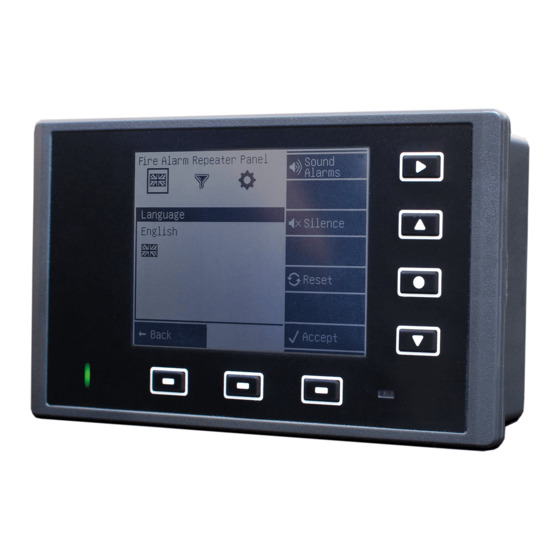
Page 31: Change The Gui Language
D. Note: The device will save the new language setting upon exiting the engineer menu. Note if the selected language is not available in the current device firmware the language will return to the previous setting. RDM0012 Issue 1 AA Page 31 of 35 © Protec Fire Detection PLC 2017... -
Page 32: Event Category Enablement
D. Back in access level 1, the icons of disabled categories will be greyed out to represent the setting. E. Note: The device will save the new setting upon exiting the engineer menu. RDM0012 Issue 1 AA Page 32 of 35 © Protec Fire Detection PLC 2017... -
Page 33: Default Access Codes
Default Access Codes The 6000/LOOP/REPEATER is shipped with the following default access codes. Default level 2 access code: 1 8 4 8 Default level 3 access code: 3 1 4 4 It is strongly recommended that these access codes are changed upon the installation of the device. -
Page 34: Appendix 1 - Installation Template
Appendix 1 - Installation Template All dimensions in mm. RDM0012 Issue 1 AA Page 34 of 35 © Protec Fire Detection PLC 2017... - Page 35 Designed and Manufactured in the United Kingdom RDM0012 Issue 1 AA Page 35 of 35 © Protec Fire Detection PLC 2017...
Need help?
Do you have a question about the 6000/LOOP/REPEATER and is the answer not in the manual?
Questions and answers